JP5872007B1 - レゾルバステータ - Google Patents
レゾルバステータ Download PDFInfo
- Publication number
- JP5872007B1 JP5872007B1 JP2014191024A JP2014191024A JP5872007B1 JP 5872007 B1 JP5872007 B1 JP 5872007B1 JP 2014191024 A JP2014191024 A JP 2014191024A JP 2014191024 A JP2014191024 A JP 2014191024A JP 5872007 B1 JP5872007 B1 JP 5872007B1
- Authority
- JP
- Japan
- Prior art keywords
- insulator
- resolver stator
- protrusion
- insulator body
- rotation axis
- Prior art date
- Legal status (The legal status is an assumption and is not a legal conclusion. Google has not performed a legal analysis and makes no representation as to the accuracy of the status listed.)
- Expired - Fee Related
Links
Images


Classifications
-
- G—PHYSICS
- G01—MEASURING; TESTING
- G01D—MEASURING NOT SPECIALLY ADAPTED FOR A SPECIFIC VARIABLE; ARRANGEMENTS FOR MEASURING TWO OR MORE VARIABLES NOT COVERED IN A SINGLE OTHER SUBCLASS; TARIFF METERING APPARATUS; MEASURING OR TESTING NOT OTHERWISE PROVIDED FOR
- G01D5/00—Mechanical means for transferring the output of a sensing member; Means for converting the output of a sensing member to another variable where the form or nature of the sensing member does not constrain the means for converting; Transducers not specially adapted for a specific variable
- G01D5/12—Mechanical means for transferring the output of a sensing member; Means for converting the output of a sensing member to another variable where the form or nature of the sensing member does not constrain the means for converting; Transducers not specially adapted for a specific variable using electric or magnetic means
- G01D5/14—Mechanical means for transferring the output of a sensing member; Means for converting the output of a sensing member to another variable where the form or nature of the sensing member does not constrain the means for converting; Transducers not specially adapted for a specific variable using electric or magnetic means influencing the magnitude of a current or voltage
- G01D5/20—Mechanical means for transferring the output of a sensing member; Means for converting the output of a sensing member to another variable where the form or nature of the sensing member does not constrain the means for converting; Transducers not specially adapted for a specific variable using electric or magnetic means influencing the magnitude of a current or voltage by varying inductance, e.g. by a movable armature
- G01D5/204—Mechanical means for transferring the output of a sensing member; Means for converting the output of a sensing member to another variable where the form or nature of the sensing member does not constrain the means for converting; Transducers not specially adapted for a specific variable using electric or magnetic means influencing the magnitude of a current or voltage by varying inductance, e.g. by a movable armature by influencing the mutual induction between two or more coils
- G01D5/2046—Mechanical means for transferring the output of a sensing member; Means for converting the output of a sensing member to another variable where the form or nature of the sensing member does not constrain the means for converting; Transducers not specially adapted for a specific variable using electric or magnetic means influencing the magnitude of a current or voltage by varying inductance, e.g. by a movable armature by influencing the mutual induction between two or more coils by a movable ferromagnetic element, e.g. a core
-
- H—ELECTRICITY
- H02—GENERATION; CONVERSION OR DISTRIBUTION OF ELECTRIC POWER
- H02K—DYNAMO-ELECTRIC MACHINES
- H02K24/00—Machines adapted for the instantaneous transmission or reception of the angular displacement of rotating parts, e.g. synchro, selsyn
-
- H—ELECTRICITY
- H02—GENERATION; CONVERSION OR DISTRIBUTION OF ELECTRIC POWER
- H02K—DYNAMO-ELECTRIC MACHINES
- H02K3/00—Details of windings
- H02K3/32—Windings characterised by the shape, form or construction of the insulation
- H02K3/34—Windings characterised by the shape, form or construction of the insulation between conductors or between conductor and core, e.g. slot insulation
- H02K3/345—Windings characterised by the shape, form or construction of the insulation between conductors or between conductor and core, e.g. slot insulation between conductor and core, e.g. slot insulation
-
- H—ELECTRICITY
- H02—GENERATION; CONVERSION OR DISTRIBUTION OF ELECTRIC POWER
- H02K—DYNAMO-ELECTRIC MACHINES
- H02K3/00—Details of windings
- H02K3/46—Fastening of windings on the stator or rotor structure
- H02K3/52—Fastening salient pole windings or connections thereto
- H02K3/521—Fastening salient pole windings or connections thereto applicable to stators only
- H02K3/522—Fastening salient pole windings or connections thereto applicable to stators only for generally annular cores with salient poles
-
- H—ELECTRICITY
- H02—GENERATION; CONVERSION OR DISTRIBUTION OF ELECTRIC POWER
- H02K—DYNAMO-ELECTRIC MACHINES
- H02K2203/00—Specific aspects not provided for in the other groups of this subclass relating to the windings
- H02K2203/06—Machines characterised by the wiring leads, i.e. conducting wires for connecting the winding terminations
Landscapes
- Engineering & Computer Science (AREA)
- Power Engineering (AREA)
- Physics & Mathematics (AREA)
- General Physics & Mathematics (AREA)
- Insulation, Fastening Of Motor, Generator Windings (AREA)
- Transmission And Conversion Of Sensor Element Output (AREA)
Abstract
Description
前記渡り線は、前記回転軸に対して平行な方向で前記突出部と隣接している。
前記インシュレータ本体内面は、平面状に形成されている。
前記インシュレータは、前記回転軸に対して平行な方向で前記突出部から突出する保持突起を更に含み、前記渡り線は、前記インシュレータ本体内面と前記保持突起の間を通っている。
前記インシュレータには、前記渡り線が前記突出部を乗り越えることなく前記突出部を挟んで反対側へと抜けるための連絡路が形成されている。
前記連絡路は、2つ形成されており、前記渡り線の両端が前記2つの連絡路を通じて、前記突出部を挟んで反対側へ引き出されている。
前記インシュレータ本体内面は、周方向において隣り合う第1インシュレータ本体内面と第2インシュレータ本体内面を有し、前記第1インシュレータ本体内面と前記第2インシュレータ本体内面は何れも平面状に形成されており、前記第1インシュレータ本体内面と前記第2インシュレータ本体内面の間の角度は180度未満である。
前記インシュレータは、前記回転軸に対して平行な方向で前記突出部から突出する保持突起を更に含み、前記渡り線は、前記インシュレータ本体内面と前記保持突起の間を通っている。
前記保持突起は、前記第1インシュレータ本体内面と前記第2インシュレータ本体内面の交線又は仮想的な交線の近傍に配置されている。
前記レゾルバステータは前記渡り線を複数備え、前記複数の渡り線は、周方向において隣り合う2つの前記コイル間において、束状に重なり合いつつ、前記回転軸に対して平行な方向で前記突出部に対向すると共に、前記回転軸に対して直交する方向で前記インシュレータ本体内面と対向するように配置される。
前記レゾルバステータは前記渡り線を複数備え、前記インシュレータは、前記突出部よりも更に内周側に突出する追加突出部を更に含み、周方向において隣り合う2つの前記コイル間において、前記複数の渡り線のうち何れかの渡り線は、前記回転軸に対して平行な方向で前記突出部と対向すると共に、前記回転軸に対して直交する方向で前記インシュレータ本体内面と対向するように配置され、前記複数の渡り線のうち他の渡り線は、前記回転軸に対して平行な方向で前記追加突出部と対向すると共に、前記回転軸に対して直交する方向で前記突出部と対向するように配置される。
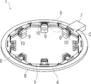
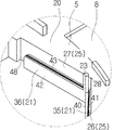
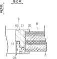
以下、図1〜図10を参照して、第1実施形態を説明する。
次に、図11を参照して、第2実施形態を説明する。以下、本実施形態が上記第1実施形態と相違する点を中心に説明し、重複する説明は省略する。
2 レゾルバロータ
3 レゾルバ
4 ステータコア
5 インシュレータ
6 ステータ巻線
7 端子台
8 ステータコア本体
9 ティース部
10 コイル
11 渡り線
12 出力端子
13 端子保持部
20 インシュレータ本体
21 突出部
22 ティース絶縁部
23 保持突起
24 内周縁
25 インシュレータ本体内面
26 第1インシュレータ本体内面(インシュレータ本体内面)
27 第2インシュレータ本体内面(インシュレータ本体内面)
28 交線
30 本体上面
31 本体下面
32 渡り線保持突起
33 渡り線保護壁
35 第1突出部(突出部)
36 第2突出部(突出部)
40 第1突出部内面
41 第1突出部底面
42 第2突出部内面
43 第2突出部底面
45 端部
46 第1連絡路(連絡路)
47 端部
48 第2連絡路(連絡路)
50 端部
51 端部
60 追加突出部
P 段差
S 空間
θ2 角度
θ1 角度
Claims (11)
- 環状のステータコア本体と前記ステータコア本体から内周側に突出する複数のティース部を有するステータコアと、
前記ステータコア本体よりも前記内周側に配置されるインシュレータと、
前記複数のティース部に夫々巻かれた複数のコイルと、
前記複数のコイルを相互に電気的に連結する渡り線と、
を備えたレゾルバステータであって、
前記インシュレータは、
前記内周側を向くインシュレータ本体内面を有するインシュレータ本体と、
前記インシュレータ本体内面よりも前記内周側に突出する突出部と、
を含み、
前記渡り線は、
前記レゾルバステータの回転軸に対して平行な方向で前記突出部と対向すると共に、
前記回転軸に対して直交する方向で前記インシュレータ本体内面と対向するように配置される、
レゾルバステータ。 - 請求項1に記載のレゾルバステータであって、
前記渡り線は、前記回転軸に対して平行な方向で前記突出部と隣接している、
レゾルバステータ。 - 請求項1又は2に記載のレゾルバステータであって、
前記インシュレータ本体内面は、平面状に形成されている、
レゾルバステータ。 - 請求項1〜3の何れかに記載のレゾルバステータであって、
前記インシュレータは、前記回転軸に対して平行な方向で前記突出部から突出する保持突起を更に含み、
前記渡り線は、前記インシュレータ本体内面と前記保持突起の間を通っている、
レゾルバステータ。 - 請求項1〜4の何れかに記載のレゾルバステータであって、
前記インシュレータには、前記渡り線が前記突出部を乗り越えることなく前記突出部を挟んで反対側へと抜けるための連絡路が形成されている、
レゾルバステータ。 - 請求項5に記載のレゾルバステータであって、
前記連絡路は、2つ形成されており、
前記渡り線の両端が前記2つの連絡路を通じて、前記突出部を挟んで反対側へ引き出されている、
レゾルバステータ。 - 請求項1又は2に記載のレゾルバステータであって、
前記インシュレータ本体内面は、周方向において隣り合う第1インシュレータ本体内面と第2インシュレータ本体内面を有し、
前記第1インシュレータ本体内面と前記第2インシュレータ本体内面は何れも平面状に形成されており、
前記第1インシュレータ本体内面と前記第2インシュレータ本体内面の間の角度は180度未満である、
レゾルバステータ。 - 請求項7に記載のレゾルバステータであって、
前記インシュレータは、前記回転軸に対して平行な方向で前記突出部から突出する保持突起を更に含み、
前記渡り線は、前記インシュレータ本体内面と前記保持突起の間を通っている、
レゾルバステータ。 - 請求項8に記載のレゾルバステータであって、
前記保持突起は、前記第1インシュレータ本体内面と前記第2インシュレータ本体内面の交線又は仮想的な交線の近傍に配置されている、
レゾルバステータ。 - 請求項1〜9の何れかに記載のレゾルバステータであって、
前記レゾルバステータは前記渡り線を複数備え、
前記複数の渡り線は、周方向において隣り合う2つの前記コイル間において、
束状に重なり合いつつ、
前記回転軸に対して平行な方向で前記突出部に対向すると共に、
前記回転軸に対して直交する方向で前記インシュレータ本体内面と対向するように配置される、
レゾルバステータ。 - 請求項1〜9の何れかに記載のレゾルバステータであって、
前記レゾルバステータは前記渡り線を複数備え、
前記インシュレータは、前記突出部よりも更に内周側に突出する追加突出部を更に含み、
周方向において隣り合う2つの前記コイル間において、
前記複数の渡り線のうち何れかの渡り線は、前記回転軸に対して平行な方向で前記突出部と対向すると共に、前記回転軸に対して直交する方向で前記インシュレータ本体内面と対向するように配置され、
前記複数の渡り線のうち他の渡り線は、前記回転軸に対して平行な方向で前記追加突出部と対向すると共に、前記回転軸に対して直交する方向で前記突出部と対向するように配置される、
レゾルバステータ。
Priority Applications (5)
| Application Number | Priority Date | Filing Date | Title |
|---|---|---|---|
| JP2014191024A JP5872007B1 (ja) | 2014-09-19 | 2014-09-19 | レゾルバステータ |
| CN201580042358.3A CN106663985B (zh) | 2014-09-19 | 2015-09-10 | 旋转变压器定子 |
| PCT/JP2015/004618 WO2016042745A1 (ja) | 2014-09-19 | 2015-09-10 | レゾルバステータ |
| EP15842579.3A EP3197021B1 (en) | 2014-09-19 | 2015-09-10 | Resolver stator |
| US15/505,274 US10634517B2 (en) | 2014-09-19 | 2015-09-10 | Resolver stator |
Applications Claiming Priority (1)
| Application Number | Priority Date | Filing Date | Title |
|---|---|---|---|
| JP2014191024A JP5872007B1 (ja) | 2014-09-19 | 2014-09-19 | レゾルバステータ |
Publications (2)
| Publication Number | Publication Date |
|---|---|
| JP5872007B1 true JP5872007B1 (ja) | 2016-03-01 |
| JP2016063679A JP2016063679A (ja) | 2016-04-25 |
Family
ID=55362148
Family Applications (1)
| Application Number | Title | Priority Date | Filing Date |
|---|---|---|---|
| JP2014191024A Expired - Fee Related JP5872007B1 (ja) | 2014-09-19 | 2014-09-19 | レゾルバステータ |
Country Status (5)
| Country | Link |
|---|---|
| US (1) | US10634517B2 (ja) |
| EP (1) | EP3197021B1 (ja) |
| JP (1) | JP5872007B1 (ja) |
| CN (1) | CN106663985B (ja) |
| WO (1) | WO2016042745A1 (ja) |
Cited By (4)
| Publication number | Priority date | Publication date | Assignee | Title |
|---|---|---|---|---|
| JP2017143630A (ja) * | 2016-02-09 | 2017-08-17 | 日本航空電子工業株式会社 | レゾルバステータ |
| JP2017189048A (ja) * | 2016-04-07 | 2017-10-12 | 多摩川精機株式会社 | レゾルバステータ巻線の巻線構造及び方法 |
| WO2018074338A1 (ja) * | 2016-10-19 | 2018-04-26 | 日本航空電子工業株式会社 | レゾルバステータ |
| CN110753829A (zh) * | 2017-06-21 | 2020-02-04 | 舍弗勒技术股份两合公司 | 用于旋转变压器的定子、旋转变压器和其应用方法 |
Families Citing this family (7)
| Publication number | Priority date | Publication date | Assignee | Title |
|---|---|---|---|---|
| JP6647908B2 (ja) * | 2016-02-18 | 2020-02-14 | 日本航空電子工業株式会社 | レゾルバステータ |
| MY208447A (en) * | 2019-01-29 | 2025-05-09 | Panasonic Corp | Stator, motor and air supply device thereof |
| DE102019121184A1 (de) | 2019-08-06 | 2021-02-11 | Schaeffler Technologies AG & Co. KG | Elektrische Maschine |
| DE102021205244A1 (de) | 2021-05-21 | 2022-11-24 | Brose Fahrzeugteile SE & Co. Kommanditgesellschaft, Würzburg | Verfahren zur Ausbildung einer Statorwicklung, Vollblechstator und Elektromotor |
| JP2023023784A (ja) * | 2021-08-06 | 2023-02-16 | 日本電産株式会社 | 導線の引き回し構造、モータ、レゾルバ及び電子機器の製造方法 |
| EP4293875A1 (de) * | 2022-06-15 | 2023-12-20 | Vorwerk & Co. Interholding GmbH | Elektromotor, küchenmaschine und montageverfahren |
| DE102023200955A1 (de) | 2023-02-07 | 2024-08-08 | Robert Bosch Gesellschaft mit beschränkter Haftung | Isoliermaske und ein Stator einer elektrischen Maschine, eine elektrische Maschine, sowie Verfahren zum Herstellen einer solchen |
Citations (8)
| Publication number | Priority date | Publication date | Assignee | Title |
|---|---|---|---|---|
| JPS6132778U (ja) * | 1984-07-27 | 1986-02-27 | 株式会社安川電機 | インダクタ形レゾルバ |
| JP2003207370A (ja) * | 2002-01-11 | 2003-07-25 | Okuma Corp | リラクタンス型レゾルバ |
| US20040056552A1 (en) * | 2002-07-30 | 2004-03-25 | Minebea Co., Ltd., | Stator device |
| JP2009131033A (ja) * | 2007-11-22 | 2009-06-11 | Tamagawa Seiki Co Ltd | レゾルバの絶縁カバー構造 |
| JP2009264892A (ja) * | 2008-04-24 | 2009-11-12 | Tamagawa Seiki Co Ltd | レゾルバの渡り線傷付及び浮き防止構造 |
| JP2013198268A (ja) * | 2012-03-19 | 2013-09-30 | Jtekt Corp | レゾルバ |
| JP5414918B1 (ja) * | 2013-01-31 | 2014-02-12 | 日本航空電子工業株式会社 | レゾルバのステータ及びレゾルバ |
| JP2015149878A (ja) * | 2014-02-10 | 2015-08-20 | 三菱電機株式会社 | 回転角度検出装置 |
Family Cites Families (10)
| Publication number | Priority date | Publication date | Assignee | Title |
|---|---|---|---|---|
| JPS6132778A (ja) | 1984-07-26 | 1986-02-15 | Canon Inc | 記録装置 |
| JPH09121520A (ja) | 1995-10-25 | 1997-05-06 | Kokusan Denki Co Ltd | 回転子内転形磁石発電機の固定子 |
| US6831389B2 (en) * | 2001-07-11 | 2004-12-14 | Kabushiki Kaisha Moric | Stator coil structure for revolving-field electrical machine and method of manufacturing same |
| JP3980402B2 (ja) * | 2002-05-13 | 2007-09-26 | 本田技研工業株式会社 | 回転電機 |
| JP3977138B2 (ja) * | 2002-05-13 | 2007-09-19 | 本田技研工業株式会社 | 回転電機 |
| US7135799B2 (en) * | 2003-03-19 | 2006-11-14 | Pacsci Motion Control, Inc. | Method for winding a stator of multi-phase motors |
| JP5067167B2 (ja) * | 2006-06-09 | 2012-11-07 | 日本電産株式会社 | ブラシレスモータ及びファンユニット |
| JP5092412B2 (ja) * | 2007-01-12 | 2012-12-05 | 日本電産株式会社 | レゾルバおよびレゾルバの製造方法 |
| EP2139094B1 (de) * | 2008-06-26 | 2018-10-17 | ZF Friedrichshafen AG | Stator mit Verschaltungsanordnung einer elektrischen Maschine |
| JP2014153069A (ja) * | 2013-02-05 | 2014-08-25 | Jtekt Corp | レゾルバ及びレゾルバ付き転がり軸受装置 |
-
2014
- 2014-09-19 JP JP2014191024A patent/JP5872007B1/ja not_active Expired - Fee Related
-
2015
- 2015-09-10 EP EP15842579.3A patent/EP3197021B1/en active Active
- 2015-09-10 CN CN201580042358.3A patent/CN106663985B/zh not_active Expired - Fee Related
- 2015-09-10 WO PCT/JP2015/004618 patent/WO2016042745A1/ja not_active Ceased
- 2015-09-10 US US15/505,274 patent/US10634517B2/en not_active Expired - Fee Related
Patent Citations (8)
| Publication number | Priority date | Publication date | Assignee | Title |
|---|---|---|---|---|
| JPS6132778U (ja) * | 1984-07-27 | 1986-02-27 | 株式会社安川電機 | インダクタ形レゾルバ |
| JP2003207370A (ja) * | 2002-01-11 | 2003-07-25 | Okuma Corp | リラクタンス型レゾルバ |
| US20040056552A1 (en) * | 2002-07-30 | 2004-03-25 | Minebea Co., Ltd., | Stator device |
| JP2009131033A (ja) * | 2007-11-22 | 2009-06-11 | Tamagawa Seiki Co Ltd | レゾルバの絶縁カバー構造 |
| JP2009264892A (ja) * | 2008-04-24 | 2009-11-12 | Tamagawa Seiki Co Ltd | レゾルバの渡り線傷付及び浮き防止構造 |
| JP2013198268A (ja) * | 2012-03-19 | 2013-09-30 | Jtekt Corp | レゾルバ |
| JP5414918B1 (ja) * | 2013-01-31 | 2014-02-12 | 日本航空電子工業株式会社 | レゾルバのステータ及びレゾルバ |
| JP2015149878A (ja) * | 2014-02-10 | 2015-08-20 | 三菱電機株式会社 | 回転角度検出装置 |
Cited By (6)
| Publication number | Priority date | Publication date | Assignee | Title |
|---|---|---|---|---|
| JP2017143630A (ja) * | 2016-02-09 | 2017-08-17 | 日本航空電子工業株式会社 | レゾルバステータ |
| JP2017189048A (ja) * | 2016-04-07 | 2017-10-12 | 多摩川精機株式会社 | レゾルバステータ巻線の巻線構造及び方法 |
| WO2018074338A1 (ja) * | 2016-10-19 | 2018-04-26 | 日本航空電子工業株式会社 | レゾルバステータ |
| JP2018068026A (ja) * | 2016-10-19 | 2018-04-26 | 日本航空電子工業株式会社 | レゾルバステータ |
| CN109690913A (zh) * | 2016-10-19 | 2019-04-26 | 日本航空电子工业株式会社 | 旋转变压器定子 |
| CN110753829A (zh) * | 2017-06-21 | 2020-02-04 | 舍弗勒技术股份两合公司 | 用于旋转变压器的定子、旋转变压器和其应用方法 |
Also Published As
| Publication number | Publication date |
|---|---|
| US10634517B2 (en) | 2020-04-28 |
| EP3197021B1 (en) | 2019-11-27 |
| CN106663985A (zh) | 2017-05-10 |
| CN106663985B (zh) | 2019-02-19 |
| US20170268904A1 (en) | 2017-09-21 |
| WO2016042745A1 (ja) | 2016-03-24 |
| JP2016063679A (ja) | 2016-04-25 |
| EP3197021A4 (en) | 2017-09-06 |
| EP3197021A1 (en) | 2017-07-26 |
Similar Documents
| Publication | Publication Date | Title |
|---|---|---|
| JP5872007B1 (ja) | レゾルバステータ | |
| JP5827840B2 (ja) | Vr型レゾルバ | |
| JP5789570B2 (ja) | ステータ | |
| CN107251373B (zh) | 旋转电机及旋转电机用绝缘件 | |
| KR101606262B1 (ko) | 보빈 및 회전 전기 기기 | |
| JP2012139075A (ja) | 回転電機 | |
| JP2018191403A (ja) | ステータおよびレゾルバ | |
| JP2017118671A (ja) | 回転電機 | |
| CN104335456A (zh) | 定子以及定子的制造方法 | |
| JP6257834B2 (ja) | 回転電機のステータ、およびその製造方法 | |
| JP5810869B2 (ja) | 回転電機用端末モジュール及びこれを備えた回転電機 | |
| JP6062134B1 (ja) | 固定子および電動機 | |
| WO2012169059A1 (ja) | 回転電機の固定子、回転電機の固定子の製造方法、及び回転電機 | |
| JP2023129460A (ja) | ステータ構造 | |
| WO2019044953A1 (ja) | ステータ構造およびレゾルバ | |
| JP2019050670A (ja) | ステータ構造およびレゾルバ | |
| WO2017110987A1 (ja) | ステータおよび回転電機 | |
| JP6647908B2 (ja) | レゾルバステータ | |
| CN107925291A (zh) | 定子线圈、定子的制造方法以及旋转电机 | |
| JP6568473B2 (ja) | ステータ | |
| JP2017034826A (ja) | レゾルバ | |
| JP2012244703A (ja) | 電動機のステータ | |
| CN203722367U (zh) | 旋转电机 | |
| JP6514978B2 (ja) | ステータ、モータおよびステータの製造方法 | |
| JP2013021834A (ja) | 回転電機およびその製造方法 |
Legal Events
| Date | Code | Title | Description |
|---|---|---|---|
| TRDD | Decision of grant or rejection written | ||
| A01 | Written decision to grant a patent or to grant a registration (utility model) |
Free format text: JAPANESE INTERMEDIATE CODE: A01 Effective date: 20151215 |
|
| A61 | First payment of annual fees (during grant procedure) |
Free format text: JAPANESE INTERMEDIATE CODE: A61 Effective date: 20160112 |
|
| R150 | Certificate of patent or registration of utility model |
Ref document number: 5872007 Country of ref document: JP Free format text: JAPANESE INTERMEDIATE CODE: R150 |
|
| R250 | Receipt of annual fees |
Free format text: JAPANESE INTERMEDIATE CODE: R250 |
|
| R250 | Receipt of annual fees |
Free format text: JAPANESE INTERMEDIATE CODE: R250 |
|
| R250 | Receipt of annual fees |
Free format text: JAPANESE INTERMEDIATE CODE: R250 |
|
| R250 | Receipt of annual fees |
Free format text: JAPANESE INTERMEDIATE CODE: R250 |
|
| LAPS | Cancellation because of no payment of annual fees |