JP5875112B2 - Twisted wire manufacturing apparatus and manufacturing method - Google Patents

Twisted wire manufacturing apparatus and manufacturing method Download PDF

Info

Publication number
JP5875112B2
JP5875112B2 JP2012047650A JP2012047650A JP5875112B2 JP 5875112 B2 JP5875112 B2 JP 5875112B2 JP 2012047650 A JP2012047650 A JP 2012047650A JP 2012047650 A JP2012047650 A JP 2012047650A JP 5875112 B2 JP5875112 B2 JP 5875112B2
Authority
JP
Japan
Prior art keywords
electric wire
twisted
wire
portions
electric
Prior art date
Legal status (The legal status is an assumption and is not a legal conclusion. Google has not performed a legal analysis and makes no representation as to the accuracy of the status listed.)
Expired - Fee Related
Application number
JP2012047650A
Other languages
Japanese (ja)
Other versions
JP2013182848A (en
Inventor
実良 間渕
実良 間渕
Current Assignee (The listed assignees may be inaccurate. Google has not performed a legal analysis and makes no representation or warranty as to the accuracy of the list.)
Yazaki Corp
Original Assignee
Yazaki Corp
Priority date (The priority date is an assumption and is not a legal conclusion. Google has not performed a legal analysis and makes no representation as to the accuracy of the date listed.)
Filing date
Publication date
Application filed by Yazaki Corp filed Critical Yazaki Corp
Priority to JP2012047650A priority Critical patent/JP5875112B2/en
Publication of JP2013182848A publication Critical patent/JP2013182848A/en
Application granted granted Critical
Publication of JP5875112B2 publication Critical patent/JP5875112B2/en
Expired - Fee Related legal-status Critical Current
Anticipated expiration legal-status Critical

Links

Images

Landscapes

  • Processes Specially Adapted For Manufacturing Cables (AREA)

Description

本願発明は、例えば電線を撚り合わせて成る撚り合わせ線の製造装置及び製造方法に係り、特に電線を捩じることにより撚り合わせ線を製造する製造装置及び製造方法に関する。   The present invention relates to a manufacturing apparatus and a manufacturing method for a stranded wire formed by twisting electric wires, for example, and more particularly to a manufacturing apparatus and a manufacturing method for manufacturing a stranded wire by twisting an electric wire.

自動車などの車両に搭載される電線には、例えばツイスト線若しくはツイストペア線と称される、いわゆる撚り合わせ線が一般的に用いられている。この撚り合わせ線は、通常、複数本の電線を互いに撚り合わせることにより製造される。例えば、図5に示すように、撚り合わせ線101が2本の電線102,103から成る構成とする。この場合、各電線102,103の一端部102a,103aを共に固定した状態で各電線102,103の他端部102b,103bを共に図5中白抜き矢印で示す向きに回転させる。これにより、一対の電線102,103が互いに密着して撚り合わされて成る撚り合わせ線101が製造される。この撚り合わせ構造により、撚り合わせ線101は、自らの電磁波の発生を抑制したり、あるいは外部からの電磁波を吸収したりすることができる。   For electric wires mounted on vehicles such as automobiles, for example, so-called twisted wires called twisted wires or twisted pair wires are generally used. This stranded wire is usually manufactured by twisting together a plurality of electric wires. For example, as shown in FIG. 5, the stranded wire 101 is composed of two electric wires 102 and 103. In this case, with the one end portions 102a and 103a of the electric wires 102 and 103 fixed together, the other end portions 102b and 103b of the electric wires 102 and 103 are both rotated in the direction indicated by the white arrows in FIG. As a result, a twisted wire 101 is manufactured in which the pair of electric wires 102 and 103 are in close contact with each other and twisted. With this twisted structure, the twisted wire 101 can suppress the generation of its own electromagnetic wave or absorb the electromagnetic wave from the outside.

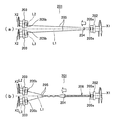
また、より具体的な撚り合わせ線の製造装置及び製造方法としては、例えば図6(a),(b)に示す撚り合わせ線の製造装置201及び製造方法が挙げられる。装置201は、一端側回転部材202、一対の他端側回転部材203、及び一端側回転部材202の側から他端側回転部材203の側に向けて移動する移動部材204などから構成されている。一端側回転部材202は、2本の電線205の一端部205aをまとめて保持するとともに、各一端部205aを各電線205の中心軸L1を中心として図6(a),(b)中矢印X1で示す向きにまとめて回転させる。ここで、矢印X1で示す向きとは、中心軸L2,L3の軸方向に沿って各他端側回転部材203の側から一端側回転部材202を臨んで見た場合に、一端側回転部材202が時計回りに回転する向きを指す。また、一対の他端側回転部材203は、各電線205の他端部205bを個別に保持するとともに、各他端部205bを中心軸L1に対して傾いた中心軸L2,L3を中心として図6(a),(b)中矢印X2で示す向きに個別に回転させる。ここで、矢印X2で示す向きとは、中心軸L2,L3の軸方向に沿って一端側回転部材202の側から各他端側回転部材203を臨んで見た場合に、各他端側回転部材203が反時計回りに回転する向きを指す。このように、一端側回転部材202と各他端側回転部材203とは、これら各回転部材202,203をそれぞれ各電線205の側から臨んで見た場合に、互いに反対向きに回転する。   Moreover, as a more specific twisted wire manufacturing apparatus and manufacturing method, for example, a twisted wire manufacturing apparatus 201 and a manufacturing method shown in FIGS. The apparatus 201 includes one end side rotating member 202, a pair of other end side rotating members 203, and a moving member 204 that moves from the one end side rotating member 202 side toward the other end side rotating member 203 side. . The one end side rotating member 202 holds the one end portions 205a of the two electric wires 205 together, and each end portion 205a is centered on the central axis L1 of each electric wire 205, and the arrow X1 in FIGS. Rotate them together in the direction indicated by. Here, the direction indicated by the arrow X1 is the one-end-side rotating member 202 when the one-end-side rotating member 202 is viewed from the other-end-side rotating member 203 side along the axial direction of the central axes L2, L3. Refers to the direction of rotating clockwise. In addition, the pair of other end-side rotating members 203 individually hold the other end 205b of each electric wire 205, and the other end 205b is illustrated with the center axes L2 and L3 inclined with respect to the center axis L1. 6 (a), (b) The individual rotations in the direction indicated by the arrow X2. Here, the direction indicated by the arrow X2 is the rotation at the other end when viewed from the one end side rotating member 202 toward the other end side rotating member 203 along the axial direction of the central axes L2 and L3. The direction in which the member 203 rotates counterclockwise is indicated. Thus, the one end side rotating member 202 and each other end side rotating member 203 rotate in opposite directions when viewed from the side of each electric wire 205 when viewed from the respective electric wire 205 side.

そして、移動部材204は、図6(a),(b)中白抜き矢印で示すように、一端側回転部材202の回転に伴って、一端側回転部材202の側から各他端側回転部材203の側に向けて中心軸L1に沿って移動する。これにより、一端側回転部材202と移動部材204との間において2本の電線205が撚り合わされて、所望の撚り合わせ線206が製造される。このような技術を用いた撚り合わせ線の製造装置及び製造方法としては、例えば下記特許文献1に開示されている発明が挙げられる。   6A and 6B, the moving member 204 is rotated from the one end side rotating member 202 side to the other end side rotating member as the one end side rotating member 202 rotates. It moves along the central axis L1 toward the 203 side. Thereby, the two electric wires 205 are twisted between the one end side rotation member 202 and the moving member 204, and the desired twisted wire 206 is manufactured. As an apparatus and a manufacturing method of a stranded wire using such a technique, for example, the invention disclosed in Patent Document 1 below can be cited.

特開2009−231157号公報JP 2009-231157 A

しかし、図5に示す撚り合わせ線の製造方法では、各電線102,103同士を密着させて撚り合わす際に各電線102,103間に摩擦力が生じ易い。各電線102,103間に摩擦力が生じると、各電線102,103にそれらを周方向に沿って伸ばす力が働いて各電線102,103に捩じれが生じる。この捩じれによるストレスは、各電線102,103の撚り合わせが終わった後においても各電線102,103に残留し易い。捩じれによるストレスが各電線102,103に残留すると、そのストレスを解消しようとする反発力が各電線102,103に蓄えられる。すると、この反発力により、各電線102,103は捩じられる前の状態に戻ろうとする。この結果、撚り合わせ線101はその撚りが解けた状態に戻ってしまうことがある。   However, in the method for manufacturing a stranded wire shown in FIG. 5, a frictional force is likely to be generated between the electric wires 102 and 103 when the electric wires 102 and 103 are brought into close contact with each other. When a frictional force is generated between the electric wires 102 and 103, the electric wires 102 and 103 are subjected to a force for extending them in the circumferential direction, and the electric wires 102 and 103 are twisted. The stress due to the twist is likely to remain in the electric wires 102 and 103 even after the electric wires 102 and 103 are twisted together. When the stress due to twisting remains in each of the electric wires 102 and 103, a repulsive force for eliminating the stress is stored in each of the electric wires 102 and 103. Then, due to the repulsive force, the electric wires 102 and 103 try to return to the state before being twisted. As a result, the stranded wire 101 may return to its untwisted state.

また、図6(a),(b)に示す撚り合わせ線の製造装置201及び製造方法では、各他端側回転部材203の回転速度が速過ぎると、各他端側回転部材203と移動部材204との間の各電線205に過度な遠心力が働いてしまう。すると、各電線205が暴れて各電線205同士が絡みつき易くなり、各電線205の適正な撚り合わせ作業が困難になる。   Further, in the twisted wire manufacturing apparatus 201 and the manufacturing method shown in FIGS. 6A and 6B, if the rotational speed of each other-end-side rotating member 203 is too high, each other-end-side rotating member 203 and the moving member. An excessive centrifugal force will act on each electric wire 205 between 204. Then, the electric wires 205 are violated and the electric wires 205 are easily entangled with each other, making it difficult to properly twist the electric wires 205.

本願発明は、以上説明した課題を解決するためになされたものであり、その目的とするところは、撚り合わせが容易で且つ解け難い撚り合わせ線の製造装置及び製造方法を提供することにある。   The present invention has been made to solve the above-described problems, and an object of the present invention is to provide an apparatus and a method for manufacturing a twisted wire that is easy to twist and difficult to unwind.

前記課題を解決して目的を達成するために、本願の請求項1に係る撚り合わせ線の製造装置は、複数本の電線部がそれぞれ有する一方の端部をそれぞれ個別に把持しつつ互いに独立に回転自在な複数個の第1の端部保持具と、これら第1の各端部保持具を回転させて前記第1の各端部保持具に把持された前記各電線部をそれぞれの軸芯を中心として個別に回転させる第1の回転駆動部と、前記各電線部がそれぞれ有する他方の端部を一括して把持しつつ前記第1の各端部保持具とは独立に回転自在な第2の端部保持具と、この第2の端部保持具を回転させて前記第2の端部保持具に把持された前記各電線部を一括して回転させる第2の回転駆動部と、を具備して成り、前記第2の端部保持具の回転が停止した状態で、前記第1の各端部保持具を回転させて前記各電線部をそれぞれの前記軸芯を中心として個別に捩じり、前記第1の各端部保持具の回転が停止した状態で、前記第2の端部保持具を前記各電線部の捩じりを解消する向きに回転させて前記各電線部同士を撚り合わせることを特徴とするものである。 In order to solve the problems and achieve the object, the twisted wire manufacturing apparatus according to claim 1 of the present application is independent of each other while individually holding one end of each of the plurality of electric wire portions. A plurality of first end holders that are freely rotatable, and the electric wire portions gripped by the first end holders by rotating the first end holders, respectively. a first rotation drive section for rotating separately about the, first the freely rotating independently of each wire unit is the first of each end retainer while gripping collectively the other end with each and second end retainer, and a second rotary drive unit for rotating collectively the respective wire portion which is gripped to the second end retainer the second end retainer rotate the, comprises a made, with the rotation of said second end retainer is stopped, the first of each end retainer Rotate torsion individually each wire portion around each of the axis, in a state where the rotation of the first respective end retainer stops, the said second end retainer each The electric wires are rotated in a direction to eliminate twisting of the electric wires, and the electric wires are twisted together.

このような構成から成る本願請求項1に係る撚り合わせ線の製造装置においては、各電線部をそれぞれの軸芯を中心として個別に捩じり、且つ各電線部の捩じりを解消する向きに各電線部をまとめて回転させて各電線部同士を撚り合わせる。これにより、撚り合わされた各電線部に捩じれが殆ど生じておらず、捩じれによるストレスも殆ど残留していない撚り合わせ線を容易に製造することができる。   In the twisted wire manufacturing apparatus according to claim 1 having the above-described configuration, each wire portion is individually twisted around its axis, and the twist of each wire portion is eliminated. The electric wire portions are rotated together to twist the electric wire portions together. As a result, twisted wires are hardly produced in the twisted electric wire portions, and a twisted wire in which stress due to twisting hardly remains can be easily manufactured.

また、本願の請求項2に係る撚り合わせ線の製造装置は、本願の請求項1に記載の撚り合わせ線の製造装置において、前記複数本の電線部が、互いに独立した2本以上の第1の電線、及び少なくとも1本の連続する電線をその長手方向の中間部の少なくとも1箇所において折り返して実質的に2本以上の前記電線部とした第2の電線、のうちの少なくとも一方の前記電線から構成され、前記第1の各電線については、前記一方の各端部及び前記他方の各端部とは、それぞれ前記第1の各電線が有する長手方向の一方の端部及び他方の端部であり、前記第2の電線については、前記一方の各端部とは前記第2の電線が有する長手方向の両端部であるとともに前記他方の端部とは前記第2の電線を折り返した折り返し部であることを特徴とするものである。   A twisted wire manufacturing apparatus according to claim 2 of the present application is the twisted wire manufacturing apparatus according to claim 1 of the present application, wherein the plurality of electric wire portions are independent of each other. And at least one of the second electric wires which are substantially two or more of the electric wire portions by folding back at least one continuous electric wire at at least one of the longitudinal intermediate portions thereof. For each of the first electric wires, the one end and the other end are the one end and the other end in the longitudinal direction of the first electric wire, respectively. As for the second electric wire, each of the one end portions is a longitudinal end portion of the second electric wire and the other end portion is a folded back of the second electric wire. Also characterized by being part It is.

このような構成から成る本願請求項2に係る撚り合わせ線の製造装置によれば、撚り合わせ線の製造が、その材料となる電線の形態や種類に束縛され難い。また、1本の電線を用いて撚り合わせ線を製造することができるので、材料の無駄を省いて製造コストの低減を図ることがきる。   According to the twisted wire manufacturing apparatus according to the second aspect of the present invention having such a configuration, the manufacture of the twisted wire is not easily restricted by the form and type of the electric wire as the material. Moreover, since a twisted wire can be manufactured using one electric wire, it is possible to reduce the manufacturing cost by eliminating waste of materials.

さらに、本願の請求項3に係る撚り合わせ線の製造方法は、複数本の電線部がそれぞれ有する一方の端部をそれぞれ個別に把持するとともに、前記各電線部がそれぞれ有する他方の端部を一括して把持した状態で、前記一方の各端部をそれぞれ個別に回転させて前記各電線部をそれぞれの軸芯を中心として個別に捩じった後、前記一方の各端部の回転を停止し、前記他方の各端部を一括して前記各電線部の捩じりを解消する向きに回転させて前記各電線部同士を撚り合わせることを特徴とするものである。 Furthermore, the manufacturing method of the twisted wire according to claim 3 of the present application individually grips one end portion of each of the plurality of electric wire portions, and collectively collects the other end portion of each of the electric wire portions. and while holding it, after Tsu twisted individually said one of said electric wires portions respectively rotate individually each end around respective axial stop the rotation of each end of the one and one in which collectively each end of the front SL other is rotated in a direction to eliminate the twisting of the electric wires portions, characterized in that twisting the electric wires portions with.

このような構成から成る本願請求項3に係る撚り合わせ線の製造方法においては、各電線部をそれぞれの軸芯を中心として個別に捩じり、且つ各電線部の捩じりを解消する向きに各電線部をまとめて回転させて各電線部同士を撚り合わせる。これにより、撚り合わされた各電線部に捩じれが殆ど生じておらず、捩じれによるストレスも殆ど残留していない撚り合わせ線を容易に製造することができる。   In the method of manufacturing a stranded wire according to claim 3 having the above-described configuration, each wire portion is individually twisted around its axis, and the twist of each wire portion is eliminated. The electric wire portions are rotated together to twist the electric wire portions together. As a result, twisted wires are hardly produced in the twisted electric wire portions, and a twisted wire in which stress due to twisting hardly remains can be easily manufactured.

前述したように、本願請求項1に係る発明によれば、撚り合わされた各電線部に捩じれが殆ど生じておらず、捩じれによるストレスも殆ど残留していない撚り合わせ線を容易に製造することができる。したがって、本願請求項1に係る発明によれば、撚り合わせが容易で且つ解け難い撚り合わせ線の製造装置を提供することができる。   As described above, according to the invention according to claim 1 of the present application, it is possible to easily produce a twisted wire in which twists are hardly generated in the twisted electric wire portions and stress due to twisting hardly remains. it can. Therefore, according to the invention which concerns on Claim 1 of this application, the manufacturing apparatus of the twisted wire which is easy to twist and it is hard to unwind can be provided.

また、本願請求項2に係る発明によれば、撚り合わせ線の製造がその材料となる電線の形態や種類に束縛され難く、また材料の無駄を省いて製造コストの低減を図ることがきる。したがって、本願請求項2に係る発明によれば、本願請求項1に係る発明と同様の効果を得ることができるとともに、調達できる電線の形態や種類に応じて柔軟に対応でき、且つ安価に撚り合わせ線を製造することができる撚り合わせ線の製造装置を提供することができる。   Further, according to the invention according to claim 2 of the present application, the production of the twisted wire is not easily restricted by the form and type of the electric wire as the material, and the production cost can be reduced by eliminating the waste of the material. Therefore, according to the invention according to claim 2 of the present application, the same effect as that of the invention according to claim 1 of the present application can be obtained, and it can be flexibly handled according to the form and type of the electric wire that can be procured and twisted at a low cost. The manufacturing apparatus of the twisted wire which can manufacture a mating wire can be provided.

さらに、本願請求項3に係る発明によれば、撚り合わされた各電線部に捩じれが殆ど生じておらず、捩じれによるストレスも殆ど残留していない撚り合わせ線を容易に製造することができる。したがって、本願請求項3に係る発明によれば、撚り合わせが容易で且つ解け難い撚り合わせ線の製造方法を提供することができる。   Furthermore, according to the invention of claim 3 of the present application, it is possible to easily manufacture a twisted wire in which the twisted electric wires are hardly twisted and the stress due to twisting hardly remains. Therefore, according to the invention which concerns on Claim 3 of this application, the manufacturing method of the twisted wire which is easy to twist and it is hard to unwind can be provided.

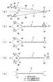
本願発明の一つの実施形態に係る撚り合わせ線の製造装置を示す斜視図である。It is a perspective view which shows the manufacturing apparatus of the twisted wire which concerns on one Embodiment of this invention. 図1に示す撚り合わせ線の製造装置の要部を拡大して示す斜視図である。It is a perspective view which expands and shows the principal part of the manufacturing apparatus of the twisted wire shown in FIG. (a),(b),(c),(d),(e)は、それぞれ図1に示す撚り合わせ線の製造装置を用いる一つの実施例に係る撚り合わせ線の製造方法を工程順に示す模式図である。(A), (b), (c), (d), and (e) show the manufacturing method of the twisted wire which concerns on one Example which uses the manufacturing apparatus of the twisted wire shown in FIG. 1, respectively in order of a process. It is a schematic diagram. (a),(b),(c),(d)は、それぞれ図3に示す一つの実施例に係る撚り合わせ線の製造方法の変形例を工程順に示す模式図である。(A), (b), (c), (d) is a schematic diagram which shows the modification of the manufacturing method of the twisted wire which concerns on one Example shown in FIG. 3 in order of a process, respectively. 従来の技術に係る撚り合わせ線の製造方法の概略を示す模式図である。It is a schematic diagram which shows the outline of the manufacturing method of the twisted wire which concerns on the prior art. 図5に示す撚り合わせ線の製造方法とは異なる従来の技術に係る撚り合わせ線の製造装置及び製造方法の概略を示す模式図である。It is a schematic diagram which shows the outline of the manufacturing apparatus and manufacturing method of the twisted wire which concern on the prior art different from the manufacturing method of the twisted wire shown in FIG.

以下、本願発明の一つの実施形態に係る撚り合わせ線の製造装置及び製造方法について、図1〜図4を参照して説明する。先ず、図1及び図2を参照しつつ撚り合わせ線の製造装置1の構成及び機能などについて説明する。   Hereinafter, an apparatus and a method for manufacturing a twisted wire according to an embodiment of the present invention will be described with reference to FIGS. First, the configuration and function of the twisted wire manufacturing apparatus 1 will be described with reference to FIGS. 1 and 2.

[撚り合わせ線の製造装置の構成及び機能]
図1に示すように、本実施形態に係る撚り合わせ線の製造装置1は、複数本の電線2を撚り合わせて成る撚り合わせ線を製造するための装置である。本実施形態においては、2本の電線2を撚り合わせて成るツイスト線(ツイストペア線)を製造する撚り合わせ線の製造装置1を例示して説明する。この製造装置1は、主に作業台3、第1の電線保持部4、第2の電線保持部5、駆動機構6、及び操作部7などから構成されている。
[Configuration and function of twisted wire manufacturing equipment]
As shown in FIG. 1, a twisted wire manufacturing apparatus 1 according to the present embodiment is a device for manufacturing a twisted wire formed by twisting a plurality of electric wires 2. In the present embodiment, a twisted wire manufacturing apparatus 1 for manufacturing a twisted wire (twisted pair wire) formed by twisting two electric wires 2 will be described as an example. The manufacturing apparatus 1 mainly includes a work table 3, a first electric wire holding unit 4, a second electric wire holding unit 5, a driving mechanism 6, an operation unit 7, and the like.

撚り合わせ線の製造装置1においては、大別して2種類の電線2を使用することができる。一方は、互いに独立した2本以上の第1の電線である。そして他方は、少なくとも1本の連続する電線をその長手方向の中間部の少なくとも1箇所において折り返して実質的に2本以上の電線部とした第2の電線である。本実施形態においては、電線2として第2の電線を採用する場合について説明する。   In the twisted wire manufacturing apparatus 1, two types of electric wires 2 can be used roughly. One is two or more first electric wires independent from each other. The other is a second electric wire in which at least one continuous electric wire is folded back at at least one location in the middle portion in the longitudinal direction to substantially form two or more electric wire portions. In this embodiment, the case where a 2nd electric wire is employ | adopted as the electric wire 2 is demonstrated.

第2の電線2は、図1に示すように、その長手方向の中間部の1箇所において折り返されて装置1に取り付けられる。具体的には、第2の電線2は、これを折り返した折り返し部2Aとその長手方向の両端部2D,2Eのそれぞれとの間の2つの領域に区分けされて装置1に取り付けられる。ここで、それら2つの領域のうち、第2の電線2の一方の端部2Dと折り返し部2Aとの間の領域を第1の電線部2Bとする。また、それら2つの領域のうち、第2の電線2の他方の端部2Eと折り返し部2Aとの間の領域を第2の電線部2Cとする。したがって、連続する1本の電線である第2の電線2は実質的に、第1及び第2の2本の電線部2B,2Cから構成される2本の電線として装置1に取り付けられる。   As shown in FIG. 1, the second electric wire 2 is folded back and attached to the device 1 at one place in the middle portion in the longitudinal direction. Specifically, the second electric wire 2 is attached to the device 1 by being divided into two regions between the folded portion 2A that is folded back and both end portions 2D and 2E in the longitudinal direction. Here, the area | region between one edge part 2D of the 2nd electric wire 2 and the folding | returning part 2A among these 2 area | regions is made into the 1st electric wire part 2B. Of these two regions, the region between the other end 2E of the second electric wire 2 and the folded portion 2A is defined as a second electric wire portion 2C. Therefore, the 2nd electric wire 2 which is one continuous electric wire is attached to the apparatus 1 as two electric wires comprised from the 1st and 2nd two electric wire parts 2B and 2C substantially.

第1の電線部2Bについては、電線2の一端部2Dが、第1の電線部2Bの一方の端部として第1の電線保持部4に保持される。それとともに、電線2の折り返し部2Aが、第1の電線部2Bの他方の端部として第2の電線保持部5に保持される。同様に、第2の電線部2Cについては、電線2の他端部2Eが、第2の電線部2Cの一方の端部として第1の電線保持部4に保持される。それとともに、電線2の折り返し部2Aが、第2の電線部2Cの他方の端部として第2の電線保持部5に保持される。   About the 1st electric wire part 2B, the one end part 2D of the electric wire 2 is hold | maintained at the 1st electric wire holding part 4 as one edge part of the 1st electric wire part 2B. At the same time, the folded portion 2A of the electric wire 2 is held by the second electric wire holding portion 5 as the other end portion of the first electric wire portion 2B. Similarly, for the second electric wire portion 2C, the other end portion 2E of the electric wire 2 is held by the first electric wire holding portion 4 as one end portion of the second electric wire portion 2C. At the same time, the folded portion 2A of the electric wire 2 is held by the second electric wire holding portion 5 as the other end portion of the second electric wire portion 2C.

なお、第1及び第2の各電線部2B,2Cのそれぞれの一端部2D,2Eは、互いに独立しているとともに個別に第1の電線保持部4に保持される。これに対して、第1及び第2の各電線部2B,2Cは、それぞれの他端部となる電線2の折り返し部2Aを共有している。したがって、第1の電線部2B及び第2の電線部2Cは、それらの他端部2Aを実質的に一括して第2の電線保持部5に保持されることとなる。このように、2本の電線2は実質的に、第2の電線保持部5に保持される折返し部2Aから第1の電線保持部4に保持される各一端部2D,2Eに向かって延びる第1及び第2の2本の電線部2B,2Cによって構成されることとなる。   The one end portions 2D and 2E of the first and second electric wire portions 2B and 2C are independent of each other and are individually held by the first electric wire holding portion 4. On the other hand, the first and second electric wire portions 2B and 2C share the folded portion 2A of the electric wire 2 that is the other end portion. Therefore, the first electric wire portion 2B and the second electric wire portion 2C are held by the second electric wire holding portion 5 with their other end portions 2A substantially collectively. As described above, the two electric wires 2 substantially extend from the folded portion 2A held by the second electric wire holding portion 5 toward the one end portions 2D and 2E held by the first electric wire holding portion 4. The first and second electric wire portions 2B and 2C are configured.

作業台3は、図1に示すように、その全体の概形を一方向に沿って延ばされた長尺形状に形成されている。作業台3は、その長手方向を概ね水平方向に沿わされて図示しない作業場に設置される。また、作業台3は、電線2を装置1に取り付けるためのテーブル31、及び第1の電線保持部4を覆うカバー32などを備えて構成されている。図示しない作業者は、例えば作業台3の長手方向と直交する作業台3の幅方向の両側部のうち一方の側部付近において作業を行う。   As shown in FIG. 1, the work table 3 is formed in an elongated shape that is extended along one direction in its general outline. The work table 3 is installed in a work place (not shown) with the longitudinal direction thereof being substantially horizontal. In addition, the work table 3 includes a table 31 for attaching the electric wire 2 to the device 1, a cover 32 that covers the first electric wire holding unit 4, and the like. An operator (not shown) performs work in the vicinity of one side portion of both sides in the width direction of the work table 3 orthogonal to the longitudinal direction of the work table 3, for example.

テーブル31は、作業台3の長手方向に沿って延ばされた長尺形状に形成されており、作業者が作業し易い高さに配置されている。また、テーブル31は、その全体の概形を凹溝形状に形成されており、素材若しくは材料としての電線2や製品としての撚り合わせ線を受け入れ易く設定されている。これらにより、作業者は、テーブル31の上で引き延ばした電線2を折り曲げて第1及び第2の各電線保持部4,5に保持させる作業を行い易い。   The table 31 is formed in a long shape extending along the longitudinal direction of the work table 3, and is arranged at a height at which an operator can easily work. Further, the table 31 is formed in a concave groove shape as a whole, and is set so as to easily accept the electric wire 2 as a material or a material and a twisted wire as a product. Thus, the operator can easily perform the work of bending the electric wire 2 extended on the table 31 and holding it by the first and second electric wire holding portions 4 and 5.

カバー32は、図1の左上側に示すテーブル31及び作業台3の長手方向の一方の端部に設けられている。カバー32は、テーブル31に対して図1中両向き矢印Aで示す向きに沿って回動自在に支持されている。即ち、カバー32は、第1の電線保持部4を覆う状態から上方に開いて、第1の電線保持部4を作業者が操作できる状態まで開閉可能に構成されている。   The cover 32 is provided at one end in the longitudinal direction of the table 31 and the work table 3 shown on the upper left side of FIG. The cover 32 is supported so as to be rotatable with respect to the table 31 along the direction indicated by the double arrow A in FIG. That is, the cover 32 is configured to open upward from a state of covering the first electric wire holding part 4 and to be opened and closed until the operator can operate the first electric wire holding part 4.

第1の電線保持部4は、図1及び図2に示すように、第1及び第2の各電線部2B,2Cのそれぞれの一端部2D,2Eを個別に保持する。この第1の電線保持部4は、テーブル31及び作業台3の長手方向の一方の端部に設けられている。また、第1の電線保持部4は、図1に示すように、第1のベース板41、一対の第1の軸支部42、及び一対の第1の端部保持具43などを備えて構成されている。第1のベース板41は、平板形状且つ矩形状に形成されてテーブル31若しくは作業台3に固定されている。また、一対の第1の軸支部42は共に第1のベース板51に直接固定されている。そして、一対の第1の端部保持具43は、それぞれ互いに独立に回転可能且つ回転を規制可能に設定されて一対の第1の軸支部42に支持されている。第1の各端部保持具43は、図2中白抜きの両向き矢印B,Cで示すように、それぞれの軸支部42に対して時計回り及び反時計回りの正逆両方向に向けて回転自在である。   As shown in FIGS. 1 and 2, the first electric wire holding portion 4 individually holds the respective one end portions 2D and 2E of the first and second electric wire portions 2B and 2C. The first electric wire holding portion 4 is provided at one end in the longitudinal direction of the table 31 and the work table 3. Moreover, the 1st electric wire holding part 4 is provided with the 1st base board 41, a pair of 1st axial support part 42, a pair of 1st edge part holder 43, etc., as shown in FIG. Has been. The first base plate 41 is formed in a flat plate shape and a rectangular shape, and is fixed to the table 31 or the work table 3. The pair of first shaft support portions 42 are both directly fixed to the first base plate 51. The pair of first end holders 43 are set to be able to rotate independently of each other and to be capable of restricting rotation, and are supported by the pair of first shaft support portions 42. Each of the first end holders 43 rotates in the clockwise and counterclockwise forward and reverse directions with respect to the respective shaft support portions 42, as indicated by white double arrows B and C in FIG. It is free.

第1の各端部保持具43は、図1及び図2に示すように、第1及び第2の各電線部2B,2Cのそれぞれの一端部2D,2Eを個別に保持する。これら第1の各端部保持具43は、テーブル31及び作業台3の幅方向において互いに離間されて配置されており、回転駆動される際に互いに干渉し合わない設定となっている。ひいては、第1の各端部保持具43同士の間隔は、それら第1の各端部保持具43が個別に保持している第1の電線部2Bと第2の電線部2Cとが回転駆動されて捩じられる際に、互いに干渉し合わない大きさに設定されている。この第1の各端部保持具43同士の間隔は、例えば第1の各端部保持具43の回転速度、製造する撚り合わせ線の材料となる電線2の径の大きさや硬さ、撚り合わせ線の撚り合わせのピッチの大きさ、あるいは撚り合わせの目の細かさ若しくは粗さ等々に応じて適宜、適正な大きさに設定される。第1の各端部保持具43は、それぞれ第1の回転軸44、第1の回転体45、第1の把持受部46、第1の把持部47、及び第1の把持操作レバー48などを有して構成されている。   As shown in FIGS. 1 and 2, the first end holders 43 individually hold the one end portions 2D and 2E of the first and second electric wire portions 2B and 2C, respectively. Each of the first end holders 43 is disposed so as to be separated from each other in the width direction of the table 31 and the work table 3 and is set so as not to interfere with each other when being rotated. As a result, the distance between the first end holders 43 is such that the first electric wire portion 2B and the second electric wire portion 2C held individually by the first end holders 43 are rotationally driven. The size is set so as not to interfere with each other when twisted. The spacing between the first end holders 43 is, for example, the rotational speed of the first end holders 43, the size and hardness of the wire 2 that is the material of the stranded wire to be manufactured, and twisting. An appropriate size is appropriately set according to the size of the twisting pitch of the wires or the fineness or roughness of the twisting. Each first end holder 43 includes a first rotating shaft 44, a first rotating body 45, a first grip receiving portion 46, a first grip portion 47, a first grip operation lever 48, and the like. It is comprised.

第1の回転軸44は、テーブル31及び作業台3の長手方向に沿って延ばされて設けられている。この第1の回転軸44は、第1の軸支部42に回転可能に支持されている。これにより、図2中白抜きの両向き矢印B,Cで示すように、第1の回転軸44は、その軸周りに沿って時計回り及び反時計回りの正逆両方向に向けて回転自在である。第1の回転体45は、第1の回転軸44に固定されて第1の回転軸44と一体に回転する。第1の把持受部46は、第1の回転体45の第1の回転軸44に取り付けられている側とは反対側である第1の回転体45の先端側に設けられている。即ち、第1の把持受部46は、第1の回転体45の第2の電線保持部5と対向する側に設けられている。第1の把持部47は、第1の把持受部46に向かって第1の回転軸44の軸方向と直交する方向から進退自在に設けられている。第1の把持部47は、図示しないばね機構やロック機構などを有しており、第1及び第2の各電線部2B,2Cのそれぞれの一端部2D,2Eを第1の把持受部46との間に把持(チャック)可能に構成されている。第1の把持操作レバー48は、これを操作することにより第1の把持部47を第1の回転体45に対して進退移動させる。   The first rotating shaft 44 is provided so as to extend along the longitudinal direction of the table 31 and the work table 3. The first rotation shaft 44 is rotatably supported by the first shaft support portion 42. As a result, as shown by white double-headed arrows B and C in FIG. 2, the first rotation shaft 44 is rotatable in the clockwise and counterclockwise forward and reverse directions along the axis. is there. The first rotating body 45 is fixed to the first rotating shaft 44 and rotates integrally with the first rotating shaft 44. The first grip receiving portion 46 is provided on the distal end side of the first rotating body 45 that is opposite to the side attached to the first rotating shaft 44 of the first rotating body 45. That is, the first grip receiving portion 46 is provided on the side of the first rotating body 45 facing the second electric wire holding portion 5. The first grip portion 47 is provided so as to be able to advance and retract from the direction orthogonal to the axial direction of the first rotation shaft 44 toward the first grip receiving portion 46. The first grip 47 has a spring mechanism, a lock mechanism, and the like (not shown), and the first grip receiving portion 46 is connected to the first ends 2D and 2E of the first and second electric wire portions 2B and 2C, respectively. It can be held (chucked) between. The first grip operation lever 48 moves the first grip portion 47 with respect to the first rotating body 45 by operating this.

第2の電線保持部5は、図1及び図2に示すように、第1及び第2の各電線部2B,2Cのそれぞれの他端部となる第2の電線2の折り返し部2Aを一箇所で保持する。この第2の電線保持部5は、テーブル31及び作業台3の長手方向において第1の電線保持部4に対向して配置されている。即ち、第2の電線保持部5は、図1の右下側に示すテーブル31及び作業台3の長手方向の他方の端部に設けられている。このような構成により、第1及び第2の各電線部2B,2Cは、第1の電線保持部4と第2の電線保持部5との間でそれぞれ略直線状に引っ張られて保持される。   As shown in FIGS. 1 and 2, the second electric wire holding portion 5 includes a folded portion 2 </ b> A of the second electric wire 2 that is the other end of each of the first and second electric wire portions 2 </ b> B and 2 </ b> C. Hold in place. The second electric wire holding part 5 is arranged to face the first electric wire holding part 4 in the longitudinal direction of the table 31 and the work table 3. That is, the second wire holding part 5 is provided at the other end in the longitudinal direction of the table 31 and the work table 3 shown on the lower right side of FIG. With such a configuration, the first and second electric wire portions 2B and 2C are each pulled and held substantially linearly between the first electric wire holding portion 4 and the second electric wire holding portion 5. .

また、この第2の電線保持部5は、図1及び図2に示すように、前述した第1の電線保持部4と同様に、第2のベース板51、第2の軸支部52、及び第2の端部保持具53などを備えて構成されている。第2のベース板51は、平板形状且つ矩形状に形成されており、その長手方向をテーブル31及び作業台3の幅方向に沿わされた姿勢でテーブル31に固定されている。また、第2の軸支部52は、第2のベース板51の長手方向の中央部に取り付けられている。これにより、第2の軸支部52は第2の端部保持具53と共にテーブル31及び作業台3の幅方向の中央部に配置される。より詳細には、第2の軸支部52は第2の端部保持具53と共に、前述した一対の第1の軸支部42が並べられている方向において、それら各軸支部42の中央部に配置される。このような構成により、第1及び第2の各電線部2B,2Cは、第1の電線保持部4と第2の電線保持部5との間の長さを互いに略同じ大きさに保持される。それとともに、第1及び第2の各電線部2B,2Cには、互いに略同じ大きさの張力が略均等に掛けられる。   In addition, as shown in FIGS. 1 and 2, the second electric wire holding portion 5 includes the second base plate 51, the second shaft support portion 52, and the like, like the first electric wire holding portion 4 described above. The second end holder 53 is provided. The second base plate 51 is formed in a flat plate shape and a rectangular shape, and is fixed to the table 31 in a posture in which the longitudinal direction thereof is along the width direction of the table 31 and the work table 3. Further, the second shaft support portion 52 is attached to the center portion in the longitudinal direction of the second base plate 51. Accordingly, the second shaft support portion 52 is disposed in the center portion in the width direction of the table 31 and the work table 3 together with the second end holder 53. More specifically, the second shaft support portion 52 is disposed at the center of each of the shaft support portions 42 in the direction in which the pair of first shaft support portions 42 are arranged together with the second end holder 53. Is done. With such a configuration, each of the first and second electric wire portions 2B and 2C is held to have substantially the same length between the first electric wire holding portion 4 and the second electric wire holding portion 5. The At the same time, the first and second electric wire portions 2B and 2C are substantially evenly applied with the same tension.

ただし、第2の軸支部52は、前述した一対の第1の軸支部42とは異なり、図示しないばね機構を有する長尺形状の2本の張力維持用レール59を介して間接的に第2のベース板51に取り付けられている。図1及び図2に示すように、これら2本の張力維持用レール59は、所定の間隔で離間された互いに平行な姿勢で第2のベース板51に固定されている。それとともに、2本の張力維持用レール59は、それらの長手方向を第2のベース板51の長手方向と直交する幅方向に沿わされた姿勢で第2のベース板51に固定されている。即ち、各張力維持用レール59は、それらの長手方向をテーブル31及び作業台3の長手方向に沿わされた姿勢でテーブル31若しくは作業台3に固定されることとなる。   However, unlike the pair of first shaft support portions 42 described above, the second shaft support portion 52 is indirectly connected to the second shaft support via two elongated tension maintaining rails 59 each having a spring mechanism (not shown). The base plate 51 is attached. As shown in FIGS. 1 and 2, these two tension maintaining rails 59 are fixed to the second base plate 51 in a mutually parallel posture separated by a predetermined interval. At the same time, the two tension maintaining rails 59 are fixed to the second base plate 51 in a posture in which the longitudinal direction thereof is along the width direction orthogonal to the longitudinal direction of the second base plate 51. That is, the tension maintaining rails 59 are fixed to the table 31 or the work table 3 in a posture in which the longitudinal direction thereof is along the longitudinal direction of the table 31 and the work table 3.

そして、第2の軸支部52は、その台座52aを介して各張力維持用レール59の上に設置されている。台座52aは、各張力維持用レール59の上をそれらの長手方向に沿って摺動自在に取り付けられている。より具体的には、台座52aは、第1及び第2の各電線部2B,2Cに掛かる張力の大きさに応じて、各張力維持用レール59に沿って往復移動する設定とされている。例えば、第1及び第2の各電線部2B,2Cに掛かる張力が、各電線部2B,2Cを適正に撚り合わせるのに必要な大きさを越えているとする。この場合、台座52aは、各張力維持用レール59に沿って第1の電線保持部4に近づく向きに移動して、各電線部2B,2Cに掛かる張力を弱める。また、第1及び第2の各電線部2B,2Cに掛かる張力が、各電線部2B,2Cを適正に撚り合わせるのに必要な大きさよりも小さいとする。この場合、台座52aは、各張力維持用レール59に沿って第1の電線保持部4から遠ざかる向きに移動して、各電線部2B,2Cに掛かる張力を強める。このような構成により、第1及び第2の各電線部2B,2Cの撚り合わせ作業中に各電線部2B,2C掛かる張力は、各電線部2B,2Cを適正に撚り合わすことができる適正な大きさに設定される。   And the 2nd axial support part 52 is installed on each rail 59 for tension maintenance via the base 52a. The pedestal 52a is slidably mounted on each of the tension maintaining rails 59 along the longitudinal direction thereof. More specifically, the pedestal 52a is set to reciprocate along each tension maintaining rail 59 in accordance with the magnitude of tension applied to the first and second electric wire portions 2B and 2C. For example, it is assumed that the tension applied to each of the first and second electric wire portions 2B and 2C exceeds a size necessary for properly twisting the electric wire portions 2B and 2C. In this case, the pedestal 52a moves in a direction approaching the first electric wire holding portion 4 along each tension maintaining rail 59 to weaken the tension applied to the electric wire portions 2B and 2C. Moreover, suppose that the tension | tensile_strength concerning each 1st and 2nd electric wire part 2B, 2C is smaller than the magnitude | size required in order to twist together each electric wire part 2B, 2C appropriately. In this case, the pedestal 52a moves in a direction away from the first electric wire holding portion 4 along the respective tension maintaining rails 59, thereby increasing the tension applied to the electric wire portions 2B and 2C. With such a configuration, the tension applied to the electric wire portions 2B and 2C during the twisting operation of the first and second electric wire portions 2B and 2C can be properly twisted together. Set to size.

また、第2の軸支部52は、前述した一対の第1の軸支部42とは異なり、第2の端部保持具53を回転駆動させる端末部回転用アクチュエータとしての機能を有して構成されている。即ち、第2の軸支部52は、第2の端部保持具53を単純に軸支するのみならず、第2の端部保持具53を回転駆動させる第2の回転駆動部としての機能を兼ね備えている。本実施形態においては、第2の回転駆動部52は、第2の端部保持具53を回転駆動させて第2の各端部保持具52に保持された第1及び第2の各電線部2B,2Cを一括して回転させる設定となっている。この第2の回転駆動部52は、後述する駆動機構6の構成要素の一部とみなすこともできる。   Further, unlike the pair of first shaft support portions 42 described above, the second shaft support portion 52 is configured to have a function as a terminal portion rotation actuator that rotationally drives the second end holder 53. ing. In other words, the second shaft support portion 52 not only simply supports the second end holder 53 but also functions as a second rotation drive portion that rotates the second end holder 53. Have both. In the present embodiment, the second rotation driving unit 52 rotates the second end holder 53 and holds the first and second electric wire parts held by the second end holders 52. The setting is such that 2B and 2C are rotated together. The second rotation drive unit 52 can also be regarded as a part of components of the drive mechanism 6 described later.

本実施形態においては、第2の回転駆動部52として、電力で作動する電動モータを採用することとする。この第2のモータ52には、後述する電装部61から回転駆動に必要な電力が供給されるとともに、その回転駆動状態を制御する制御信号が送信される。そして、第2の端部保持具53は、第2の回転駆動部としての第2のモータ52により回転可能且つ回転を規制可能に支持されている。第2の端部保持具53は、図2中白抜きの両向き矢印Dで示すように、第2のモータ52により時計回り及び反時計回りの正逆両方向に向けて回転自在である。また、この第2の各端部保持具53は、前述した第1の各端部保持具43とは独立して回転自在な設定となっている。   In the present embodiment, an electric motor that operates with electric power is employed as the second rotation drive unit 52. The second motor 52 is supplied with electric power necessary for rotational driving from an electrical component 61 described later, and a control signal for controlling the rotational driving state is transmitted. The second end holder 53 is supported by a second motor 52 as a second rotation drive unit so that the second end holder 53 can be rotated and its rotation can be restricted. The second end holder 53 can be rotated in both the clockwise and counterclockwise forward and reverse directions by the second motor 52, as indicated by the white double-headed arrow D in FIG. Further, the second end holders 53 are set so as to be rotatable independently of the first end holders 43 described above.

第2の端部保持具53は、図1及び図2に示すように、第1及び第2の各電線部2B,2Cのそれぞれの他端部としての折り返し部2Aを一箇所で保持する。この第2の端部保持具53は、前述した第1の各端部保持具43と同様の構成から成る。即ち、第2の端部保持具53は、第2の回転軸54、第2の回転体55、第2の把持受部56、第2の把持部57、及び第2の把持操作レバー58などを有して構成されている。   As shown in FIGS. 1 and 2, the second end holder 53 holds the folded portion 2A as the other end of each of the first and second electric wire portions 2B and 2C at one place. The second end holder 53 has the same configuration as the first end holder 43 described above. That is, the second end holder 53 includes the second rotating shaft 54, the second rotating body 55, the second grip receiving portion 56, the second grip portion 57, the second grip operation lever 58, and the like. It is comprised.

第2の回転軸54は、テーブル31及び作業台3の長手方向に沿って延ばされて設けられている。この第2の回転軸54は、第2のモータ52に回転駆動可能に支持されている。これにより、図2中白抜きの両向き矢印Dで示すように、第2の回転軸54は、その軸周りに沿って時計回り及び反時計回りの正逆両方向に向けて回転自在である。第2の回転体55は、第2の回転軸54に固定されて第2の回転軸54と一体に回転する。第2の把持受部56は、第2の回転体55の第2の回転軸54に取り付けられている側とは反対側である第2の回転体55の先端側に設けられている。即ち、第2の把持受部56は、第2の回転体55の第1の電線保持部4と対向する側に設けられている。第2の把持部57は、第2の把持受部56に向かって第2の回転軸54の軸方向と直交する方向から進退自在に設けられている。第2の把持部57は、図示しないばね機構やロック機構などを有しており、第1及び第2の各電線部2B,2Cのそれぞれの他端部2Aを第2の把持受部56との間に把持(チャック)可能に構成されている。第2の把持操作レバー58は、これを操作することにより第2の把持部57を第2の回転体55に対して進退移動させる。   The second rotation shaft 54 is provided so as to extend along the longitudinal direction of the table 31 and the work table 3. The second rotating shaft 54 is supported by the second motor 52 so as to be rotationally driven. As a result, as indicated by a white double-headed arrow D in FIG. 2, the second rotation shaft 54 can freely rotate in both the clockwise and counterclockwise forward and reverse directions around the axis. The second rotating body 55 is fixed to the second rotating shaft 54 and rotates integrally with the second rotating shaft 54. The second grip receiving portion 56 is provided on the distal end side of the second rotating body 55, which is the side opposite to the side attached to the second rotating shaft 54 of the second rotating body 55. That is, the second grip receiving portion 56 is provided on the side of the second rotating body 55 facing the first electric wire holding portion 4. The second grip portion 57 is provided so as to be able to advance and retract from the direction orthogonal to the axial direction of the second rotation shaft 54 toward the second grip receiving portion 56. The second grip part 57 has a spring mechanism, a lock mechanism, etc. (not shown), and the other end 2A of each of the first and second electric wire parts 2B and 2C is connected to the second grip receiving part 56. It can be held (chucked) between the two. The second grip operation lever 58 operates this to move the second grip portion 57 forward and backward with respect to the second rotating body 55.

駆動機構6は、図1及び図2に示すように、電装部61、第1の回転駆動部62、第1のギア63、第2のギア64、及び歯付きベルト65などを有して構成されている。また、前述した第2の回転駆動部としての第2のモータ52も、駆動機構6の構成要素の一部としても構わない。電装部61は、前述した第1の電線保持部4と同様に、テーブル31及び作業台3の長手方向の一端部に設けられている。ただし、電装部61は、テーブル31の上ではなく作業台3の側部に配置されており、第1の電線保持部4と物理的又は電気的に干渉し合って互いの動作を妨げるおそれがない設定とされている。電装部61は、図示しない電源及び後述する操作部7に接続されている。そして、電装部61は、操作部7における操作に基づいて、第1の回転駆動部62及び第2のモータ52に向けて回転駆動に必要な電力を供給するとともに、それらの回転駆動状態を制御する制御信号を送信する。即ち、電装部61は、駆動機構6の制御部として機能する。   As shown in FIGS. 1 and 2, the drive mechanism 6 includes an electrical component 61, a first rotation drive unit 62, a first gear 63, a second gear 64, a toothed belt 65, and the like. Has been. Further, the second motor 52 as the second rotation driving unit described above may be a part of the components of the driving mechanism 6. The electrical component 61 is provided at one end of the table 31 and the work table 3 in the longitudinal direction, similarly to the first electric wire holding unit 4 described above. However, the electrical component 61 is disposed not on the table 31 but on the side of the work table 3 and may interfere with each other by physically or electrically interfering with the first wire holding unit 4. There is no setting. The electrical unit 61 is connected to a power source (not shown) and an operation unit 7 described later. The electrical component 61 supplies electric power necessary for rotational driving to the first rotational driving unit 62 and the second motor 52 based on the operation in the operation unit 7 and controls their rotational driving state. A control signal is transmitted. That is, the electrical unit 61 functions as a control unit of the drive mechanism 6.

第1の回転駆動部62は、電装部61から供給される電力及び電装部61から送信される制御信号に基づいて、その回転駆動状態を制御される。この第1の回転駆動部62は、一対の第1の端部保持具43を回転駆動させて、第1の各端部保持具43に保持された第1及び第2の各電線部2B,2Cをそれぞれの軸芯を中心として個別に回転させる。即ち、この第1の回転駆動部62は、前述した第2の回転駆動部52と同様に、第1の各端部保持具43を回転駆動させる端末部回転用アクチュエータである。本実施形態においては、第1の回転駆動部62として、前述した第2の回転駆動部52と同様に、電力で作動する電動モータを採用することとする。以下の説明において、第1の回転駆動部62を単に第1のモータと称することとする。   The first rotational drive unit 62 is controlled in its rotational drive state based on the power supplied from the electrical component 61 and the control signal transmitted from the electrical component 61. The first rotation driving unit 62 drives the pair of first end holders 43 to rotate, and the first and second electric wire parts 2B held by the first end holders 43, 2C is individually rotated around each axis. That is, the first rotation drive unit 62 is a terminal portion rotation actuator that rotates the first end holders 43 in the same manner as the second rotation drive unit 52 described above. In the present embodiment, an electric motor that operates with electric power is employed as the first rotation drive unit 62, as with the second rotation drive unit 52 described above. In the following description, the first rotation driving unit 62 is simply referred to as a first motor.

第1のギア63は、第1のモータ62の回転軸に直接連結されているとともに、一対の第1の端部保持具43のうちの一方の保持具43の第1の回転軸44に連結されている。これに対して、第2のギア64は、一対の第1の端部保持具43のうちの他方の保持具43の第1の回転軸44には連結されているが、第1のモータ62の回転軸には直接連結されていない。なお、本実施形態においては、第1及び第2の各ギア63,64の径の大きさ及び歯数は互いに同じ値に設定されている。そして、歯付きベルト65は、第1及び第2の各ギア63,64に巻き回されている。   The first gear 63 is directly connected to the rotation shaft of the first motor 62 and is connected to the first rotation shaft 44 of one of the pair of first end holders 43. Has been. On the other hand, the second gear 64 is connected to the first rotating shaft 44 of the other holder 43 of the pair of first end holders 43, but the first motor 62. It is not directly connected to the rotating shaft. In the present embodiment, the diameter and the number of teeth of each of the first and second gears 63 and 64 are set to the same value. The toothed belt 65 is wound around the first and second gears 63 and 64.

このような構成から成る駆動機構6によれば、第1のギア63、一方の第1の回転軸44、及び一方の第1の端部保持具43は、図2中矢印Bで示す向きに沿って第1のモータ62の回転駆動に伴って直接回転駆動される。これに対して、第2のギア64、他方の第1の回転軸44、及び他方の第1の端部保持具43は、図2中矢印Cで示す向きに沿って第1のギア63から歯付きベルト65を介して間接的に回転駆動される。この際、前述したように、第1及び第2の各ギア63,64は、それらの径の大きさ及び歯数が互いに同じ値に設定されているので、互いに同じ回転速度で回転駆動される。即ち、本実施形態の駆動機構6は、1個の第1のモータ62を用いて一方及び他方の2個の第1の端部保持具43を互いに同期させて同一方向に等速度で回転駆動させる、同期回転駆動機構として構成されている。   According to the drive mechanism 6 having such a configuration, the first gear 63, the one first rotating shaft 44, and the one first end holder 43 are in the direction indicated by the arrow B in FIG. Along with this, the first motor 62 is driven to rotate directly. On the other hand, the second gear 64, the other first rotating shaft 44, and the other first end holder 43 are moved from the first gear 63 along the direction indicated by the arrow C in FIG. It is rotationally driven indirectly via a toothed belt 65. At this time, as described above, since the first and second gears 63 and 64 have the same diameter and the same number of teeth, they are driven to rotate at the same rotational speed. . That is, the drive mechanism 6 of the present embodiment uses one first motor 62 to drive one and the other two first end holders 43 to rotate in the same direction at a constant speed. It is comprised as a synchronous rotation drive mechanism.

なお、前述したように、第1のモータ62に連結されていない第2のモータ52及び第2の端部保持具53は、本来、第1のモータ62及び第1の各端部保持具43とは互いに独立に回転自在な設定とされている。ただし、第2のモータ52及び第2の端部保持具53を、第1のモータ62及び第1の各端部保持具43に同期させて互いに同一速度で回転駆動する設定としても構わない。即ち、第1及び第2の各電線部2B,2Cが第1の各端部保持具43により捩じられる回数と、第1及び第2の各電線部2B,2Cが第2の端部保持具53により撚り合わされる回数とを同数とする設定としても構わない。このような同期駆動は、第1及び第2の各モータ62,52に向けて電装部61から供給される電力及び電装部61から送信される制御信号をそれぞれ適宜、適正な値に調節することにより実施することができる。   As described above, the second motor 52 and the second end holder 53 that are not connected to the first motor 62 are originally the first motor 62 and the first end holders 43. And can be rotated independently of each other. However, the second motor 52 and the second end holder 53 may be set to rotate at the same speed in synchronization with the first motor 62 and the first end holder 43. That is, the number of times each of the first and second electric wire portions 2B and 2C is twisted by the first end holder 43 and the first and second electric wire portions 2B and 2C are held at the second end portion. The number of times of twisting by the tool 53 may be set to the same number. Such synchronous driving appropriately adjusts the electric power supplied from the electrical component 61 toward the first and second motors 62 and 52 and the control signal transmitted from the electrical component 61 to appropriate values. Can be implemented.

操作部7は、図1及び図2に示すように、第2の電線保持部5の近傍に設けられている。この操作部7は、停止中の装置1を作動させたり、あるいは作動状態の装置1を停止させたりするなど、装置1の作動状態を操作するため装置である。より具体的には、操作部7は、第1及び第2の各モータ62,52の回転駆動状態を操作するための装置である。操作部7は、第2の電線保持部5の第2のベース板51上に設けられた第1のスイッチ71及び第2のスイッチ72から成る2個のスイッチを備えている。これら第1及び第2の各スイッチ71,72は、第2のベース板51の長手方向、即ちテーブル31及び作業台3の幅方向において、図示しない作業者が作業をする側に寄せられて配置されている。このように、操作部7は、作業者が、第1の電線保持部4や駆動機構6から離れた第2の電線保持部5の側において、撚り合わせ線の製造装置1の駆動操作を実施できる設定となっている。   As shown in FIGS. 1 and 2, the operation unit 7 is provided in the vicinity of the second electric wire holding unit 5. The operation unit 7 is a device for operating the operating state of the device 1 such as operating the stopped device 1 or stopping the operating device 1. More specifically, the operation unit 7 is a device for operating the rotational drive states of the first and second motors 62 and 52. The operation unit 7 includes two switches including a first switch 71 and a second switch 72 provided on the second base plate 51 of the second electric wire holding unit 5. These first and second switches 71 and 72 are arranged in the longitudinal direction of the second base plate 51, that is, in the width direction of the table 31 and the work table 3, and are brought close to the side on which an operator (not shown) works. Has been. As described above, the operation unit 7 performs the driving operation of the twisted wire manufacturing apparatus 1 on the side of the second electric wire holding unit 5 away from the first electric wire holding unit 4 and the driving mechanism 6. It is a setting that can be done.

第1のスイッチ71は、第1のモータ62の回転駆動状態を操作するためのスイッチである。第1のモータ62がその回転駆動を停止している状態(OFF状態)において、第1のスイッチ71を作業者が1回押し下げる。すると、第1のスイッチ71から駆動機構6の電装部61に向けて信号が送信される。この信号を受信した電装部61は、第1のモータ62の回転駆動を開始する制御信号を、電装部61が備える図示しない所定の制御回路等を介して第1のモータ62に向けて送信する。この回転駆動を開始する制御信号を第1のモータ62が受信することにより、停止中の第1のモータ62はその回転駆動を開始する。   The first switch 71 is a switch for operating the rotational driving state of the first motor 62. In a state where the first motor 62 stops rotating (OFF state), the operator depresses the first switch 71 once. Then, a signal is transmitted from the first switch 71 toward the electrical unit 61 of the drive mechanism 6. The electrical component 61 that has received this signal transmits a control signal for starting the rotational drive of the first motor 62 to the first motor 62 via a predetermined control circuit (not shown) provided in the electrical component 61. . When the first motor 62 receives the control signal for starting the rotation drive, the stopped first motor 62 starts the rotation drive.

また、第1のモータ62が回転駆動している状態(ON状態)において、第1のスイッチ71を作業者が1回押し下げる。すると、第1のスイッチ71から駆動機構6の電装部61に向けて新たな信号が送信される。この新たな信号を受信した電装部61は、第1のモータ62の回転駆動を停止する制御信号を、所定の制御回路等を介して第1のモータ62に向けて送信する。この回転駆動を停止する制御信号を第1のモータ62が受信することにより、回転駆動中の第1のモータ62はその回転駆動を停止する。   Further, in a state where the first motor 62 is rotationally driven (ON state), the operator depresses the first switch 71 once. Then, a new signal is transmitted from the first switch 71 toward the electrical unit 61 of the drive mechanism 6. The electrical unit 61 that has received this new signal transmits a control signal for stopping the rotational drive of the first motor 62 toward the first motor 62 via a predetermined control circuit or the like. When the first motor 62 receives the control signal for stopping the rotation drive, the first motor 62 during the rotation drive stops the rotation drive.

また、第2のスイッチ72は、第2のモータ52の回転駆動状態を操作するためのスイッチである。第2のスイッチ72の操作方法及び機能は、前述した第1のスイッチ71の操作方法及び機能と同様である。即ち、第2のモータ52がその回転駆動を停止している状態(OFF状態)において、第2のスイッチ72を作業者が1回押し下げる。すると、第2のスイッチ72から駆動機構6の電装部61に向けて信号が送信される。この信号を受信した電装部61は、第2のモータ52の回転駆動を開始する制御信号を、所定の制御回路等を介して第2のモータ52に向けて送信する。この回転駆動を開始する制御信号を第2のモータ52が受信することにより、停止中の第2のモータ52はその回転駆動を開始する。   The second switch 72 is a switch for operating the rotational driving state of the second motor 52. The operation method and function of the second switch 72 are the same as the operation method and function of the first switch 71 described above. That is, in a state where the second motor 52 stops rotating (OFF state), the operator depresses the second switch 72 once. Then, a signal is transmitted from the second switch 72 toward the electrical component 61 of the drive mechanism 6. The electrical unit 61 that has received this signal transmits a control signal for starting the rotational drive of the second motor 52 to the second motor 52 via a predetermined control circuit or the like. When the second motor 52 receives the control signal for starting this rotational drive, the stopped second motor 52 starts its rotational drive.

また、第2のモータ52が回転駆動している状態(ON状態)において、第2のスイッチ72を作業者が1回押し下げる。すると、第2のスイッチ72から駆動機構6の電装部61に向けて新たな信号が送信される。この新たな信号を受信した電装部61は、第2のモータ52の回転駆動を停止する制御信号を、所定の制御回路等を介して第2のモータ52に向けて送信する。この回転駆動を停止する制御信号を第2のモータ52が受信することにより、回転駆動中の第1のモータ52はその回転駆動を停止する。   Further, in a state where the second motor 52 is rotationally driven (ON state), the operator depresses the second switch 72 once. Then, a new signal is transmitted from the second switch 72 toward the electrical unit 61 of the drive mechanism 6. The electrical unit 61 that has received this new signal transmits a control signal for stopping the rotation of the second motor 52 to the second motor 52 via a predetermined control circuit or the like. When the second motor 52 receives the control signal for stopping the rotational drive, the first motor 52 that is rotationally driven stops the rotational drive.

なお、本実施形態においては、第1及び第2の各スイッチ71,72は、それらの初期状態においては作業者が押し下げ可能な状態に設定されている。それとともに、作業者により押し下げられた第1及び第2の各スイッチ71,72は、それら各スイッチ71,72から作業者が手を離すことにより、初期の押し下げ可能状態に戻る設定となっている。そして、第1及び第2の各モータ62,52は、それらが回転駆動状態及び回転停止状態のいずれの状態であっても、第1及び第2の各スイッチ71,72が押し下げられない限り、その状態を維持する設定となっている。以上で、撚り合わせ線の製造装置1の構成及び機能などについての説明を終了とする。   In the present embodiment, the first and second switches 71 and 72 are set in a state in which the operator can press down in the initial state. At the same time, the first and second switches 71 and 72 pushed down by the worker are set to return to the initial pushable state when the worker releases their hands from the switches 71 and 72. . The first and second motors 62 and 52 are in any state of the rotation driving state and the rotation stop state as long as the first and second switches 71 and 72 are not pushed down. It is set to maintain that state. This is the end of the description of the configuration and function of the twisted wire manufacturing apparatus 1.

[撚り合わせ線の製造方法]
次に、前述した撚り合わせ線の製造装置1を用いる撚り合わせ線の製造方法について、主に図3及び図4を参照して説明する。先ず、主に図3を参照しつつ、本実施形態の撚り合わせ線の製造方法に係る一つの実施例について説明する。
[Manufacturing method of stranded wire]
Next, the manufacturing method of the twisted wire using the manufacturing apparatus 1 of the twisted wire mentioned above is demonstrated mainly with reference to FIG.3 and FIG.4. First, an example relating to the method for manufacturing a twisted wire of the present embodiment will be described mainly with reference to FIG.

(一つの実施例)
先ず、折り返し部2Aで折り返した電線2をテーブル31の凹溝部の上に延ばして載置する。この際、折り返し部2Aを第2の電線保持部5の側に向けて配置するとともに、第1及び第2の各電線部2B,2Cの各一端部2D,2Eを第1の電線保持部4の側に向けて配置する。
(One example)
First, the electric wire 2 folded at the folded portion 2 </ b> A is extended and placed on the concave groove portion of the table 31. At this time, the folded portion 2A is arranged toward the second electric wire holding portion 5 and the one end portions 2D and 2E of the first and second electric wire portions 2B and 2C are connected to the first electric wire holding portion 4. Place it toward the side.

次に、第2の端部保持具53の把持操作レバー58を操作して把持部57を把持受部56から離隔させた後、この把持部57と把持受部56との隙間に電線2の折り返し部2Aを挿入する。続けて、把持操作レバー58を操作して把持部57を把持受部56に接近させて、この把持部57と把持受部56との間に電線2の折り返し部2Aを把持(チャック)させる。即ち、第2の端部保持具53の把持部57と把持受部56との間に、第1及び第2の各電線部2B,2Cのそれぞれの他端部2Aを実質的に一括して把持させる。なお、この作業を行う際には、第2のモータ52を回転停止状態(OFF状態)に保持して、第2の端部保持具53が回転軸54回りに回転しない設定としておく。   Next, after operating the grip operation lever 58 of the second end holder 53 to separate the grip portion 57 from the grip receiving portion 56, the wire 2 is inserted into the gap between the grip portion 57 and the grip receiving portion 56. The folded portion 2A is inserted. Subsequently, the gripping operation lever 58 is operated to bring the gripping portion 57 close to the gripping receiving portion 56, and the folded portion 2 </ b> A of the electric wire 2 is gripped (chucked) between the gripping portion 57 and the gripping receiving portion 56. That is, the other end portions 2A of the first and second electric wire portions 2B and 2C are substantially collectively bundled between the grip portion 57 and the grip receiving portion 56 of the second end holder 53. Hold it. When this operation is performed, the second motor 52 is held in a rotation stopped state (OFF state) so that the second end holder 53 does not rotate around the rotation shaft 54.

一方、一対の第1の端部保持具43のうち、例えば第1のモータ62に直結された一方の第1の端部保持具43の把持操作レバー48を操作して把持部47を把持受部46から離隔させる。そして、把持部47と把持受部46との隙間に第1の電線部2Bの一端部2Dを挿入した後、把持操作レバー48を操作して把持部47を把持受部46に接近させる。これにより、把持部47と把持受部46との間に第1の電線部2Bの一端部2Dを把持させる。また、これと同様にして、第1のモータ62に間接的に接続された他方の第1の端部保持具43における把持部47と把持受部46との間に、第2の電線部2Cの一端部2Eを把持させる。   On the other hand, of the pair of first end holders 43, for example, the grip operation lever 48 of one first end holder 43 directly connected to the first motor 62 is operated to hold the grip part 47. Separated from the portion 46. Then, after one end 2D of the first electric wire portion 2B is inserted into the gap between the grip portion 47 and the grip receiving portion 46, the grip operation lever 48 is operated to bring the grip portion 47 closer to the grip receiving portion 46. As a result, the one end portion 2D of the first electric wire portion 2B is gripped between the grip portion 47 and the grip receiving portion 46. Similarly, the second electric wire portion 2 </ b> C is provided between the grip portion 47 and the grip receiving portion 46 in the other first end holder 43 that is indirectly connected to the first motor 62. The one end part 2E of is held.

なお、第1の各端部保持具43への各一端部2D,2Eの把持作業を行う際には、第1のモータ62を回転停止状態(OFF状態)に保持して、第1の各端部保持具43がそれぞれの回転軸44回りに回転しない設定としておく。また、第1及び第2の各電線部2B,2Cの各一端部2D,2Eを第1の各端部保持具43に把持させる際には、第1及び第2の各電線部2B,2Cに略均等に張力が掛かる設定とする。それとともに、第1及び第2の各電線部2B,2Cに弛みが生じ難い設定としておく。   Note that when the gripping operation of the one end portions 2D and 2E to the first end holder 43 is performed, the first motor 62 is held in the rotation stopped state (OFF state), and the first each It is set so that the end holders 43 do not rotate around the respective rotation shafts 44. When the first end holders 43 hold the one end portions 2D and 2E of the first and second electric wire portions 2B and 2C, the first and second electric wire portions 2B and 2C are used. The tension is applied almost evenly. At the same time, the first and second electric wire portions 2B and 2C are set so that slack is unlikely to occur.

次に、作業者が操作部7の第1のスイッチ71を1回押し下げる。すると、回転停止状態の第1のモータ62は回転を開始して回転駆動状態(ON状態)となる。これに伴って、図3(a)中白抜き矢印B,Cで示すように、第1の各端部保持具43が互いに同期して同じ向きに向けて等速度で回転し始める。また、第1の各端部保持具43に把持された第1及び第2の各電線部2B,2Cの各一端部2D,2Eも、互いに同期して同じ向きに向けて等速度で回転し始める。この際、第2の端部保持具53は回転停止状態を維持しているので、電線2の折り返し部2Aもその回転を禁止された状態に保持されている。これにより、第1の電線部2Bと第2の電線部2Cとが、図3(a)中一点鎖線S2,S3で示すそれぞれの軸芯を中心として共に同じ向きに向けて捩じられ始める。これを捩じり工程と称する。   Next, the operator depresses the first switch 71 of the operation unit 7 once. Then, the first motor 62 in the rotation stopped state starts to rotate and enters the rotation driving state (ON state). Along with this, as indicated by white arrows B and C in FIG. 3A, the first end holders 43 start to rotate at the same speed in the same direction in synchronization with each other. Also, the one end portions 2D and 2E of the first and second electric wire portions 2B and 2C held by the first end holders 43 rotate at the same speed in the same direction in synchronization with each other. start. At this time, since the second end holder 53 maintains the rotation stopped state, the folded portion 2A of the electric wire 2 is also held in a state where the rotation is prohibited. As a result, the first electric wire portion 2B and the second electric wire portion 2C start to be twisted in the same direction, with the respective shaft cores indicated by alternate long and short dash lines S2 and S3 in FIG. This is called a twisting process.

なお、この一実施例においては、第2の電線保持部5の側から第1の電線保持部4を臨んで見た場合に、第1の各端部保持具43が反時計回りに回転する設定とする。したがって、第1及び第2の各電線部2B,2Cは、第2の電線保持部5の側から第1の電線保持部4を臨んで見た場合に、それぞれの軸芯S2,S3に沿って反時計回りに捩じられることとなる。この結果、第1の電線部2Bと第2の電線部2Cとは、これらを直線状に延ばして連続する1本の電線2に戻した状態において、折り返し部2Aを境にして互いに逆向きに捩じられることとなる。   In this embodiment, each first end holder 43 rotates counterclockwise when viewed from the second electric wire holding part 5 side when facing the first electric wire holding part 4. Set. Therefore, each of the first and second electric wire portions 2B and 2C extends along the respective shaft cores S2 and S3 when the first electric wire holding portion 4 is viewed from the second electric wire holding portion 5 side. Will be twisted counterclockwise. As a result, the first electric wire portion 2B and the second electric wire portion 2C are opposite to each other with the folded portion 2A as a boundary in a state where they are linearly extended and returned to a single continuous electric wire 2. It will be twisted.

作業者は、前述した捩じり工程により、第1の電線部2B及び第2の電線部2Cがそれぞれ所望の回数ずつ捩じられたことを確認した後、操作部7の第1のスイッチ71を再び1回押し下げる。すると、回転駆動状態の第1のモータ62はその回転を停止して、再び回転停止状態となる。これに伴って、第1の各端部保持具43も、同期回転駆動状態から再び回転停止状態となる。これにより、捩じり工程を終了とする。   The operator confirms that the first electric wire portion 2B and the second electric wire portion 2C have been twisted a desired number of times by the above-described twisting process, and then the first switch 71 of the operation portion 7. Press once again. Then, the first motor 62 in the rotationally driven state stops its rotation and enters the rotation stopped state again. Along with this, the first end holders 43 are also brought into the rotation stopped state again from the synchronous rotation driving state. This completes the twisting process.

次に、作業者が操作部7の第2のスイッチ72を1回押し下げる。すると、回転停止状態の第2のモータ52は回転を開始して回転駆動状態(ON状態)となる。これに伴って、第2の端部保持具53が図3(b)中白抜き矢印Dで示す向きに向かって回転し始める。この第2の端部保持具53が回転する向きDは、第1の電線部2B及び第2の電線部2Cの捩じれを解消する向きを指す。前述したように、この一実施例においては、第1の電線部2B及び第2の電線部2Cは、第2の電線保持部5の側から第1の電線保持部4を臨んで見た場合に、反時計回りに回転する第1の各端部保持具43により捩じられる。したがって、第1の電線部2B及び第2の電線部2Cの捩じれを解消するためには、第2の電線保持部5の側から第1の電線保持部4を臨んで見た場合に、第2の端部保持具53を第1の各端部保持具43と同じ向きに回転させればよい。即ち、第2の電線保持部5の側から第1の電線保持部4を臨んで見た場合に、第1の各端部保持具43と同様に、第2の端部保持具53を反時計回りに回転させればよい。   Next, the operator depresses the second switch 72 of the operation unit 7 once. Then, the second motor 52 in the rotation stopped state starts to rotate and enters a rotation driving state (ON state). Accordingly, the second end holder 53 starts to rotate in the direction indicated by the white arrow D in FIG. The direction D in which the second end holder 53 rotates indicates the direction in which twisting of the first electric wire portion 2B and the second electric wire portion 2C is eliminated. As described above, in this embodiment, the first electric wire portion 2B and the second electric wire portion 2C are viewed from the side of the second electric wire holding portion 5 facing the first electric wire holding portion 4. And the first end holder 43 that rotates counterclockwise. Therefore, in order to eliminate the twist of the first electric wire portion 2B and the second electric wire portion 2C, when the first electric wire holding portion 4 is viewed from the second electric wire holding portion 5 side, The two end holders 53 may be rotated in the same direction as the first end holders 43. That is, when viewed from the side of the second electric wire holding part 5 facing the first electric wire holding part 4, the second end holding part 53 is bent in the same manner as the first end holding parts 43. What is necessary is just to rotate clockwise.

なお、当然のことながら、この第2の端部保持具53が回転する向きは、第1及び第2の各電線保持部4,5を逆方向から臨んで見た場合には、反時計回りとは逆向きとなる。即ち、第2の端部保持具53が回転する向きは、第1の電線保持部4の側から第2の電線保持部5を臨んで見た場合には時計回りとなる。また、当然のことながら、第2のモータ52も、第2の端部保持具53と同じく第1の電線部2B及び第2の電線部2Cの捩じれを解消する向きに向けて回転駆動する。   Of course, the direction in which the second end holder 53 rotates is counterclockwise when the first and second electric wire holders 4 and 5 are viewed from opposite directions. Is the opposite. That is, the direction in which the second end holder 53 rotates is clockwise when viewed from the side of the first electric wire holder 4 facing the second electric wire holder 5. As a matter of course, the second motor 52 is also rotationally driven in a direction to eliminate twisting of the first electric wire portion 2B and the second electric wire portion 2C, as with the second end holder 53.

第2の端部保持具53が回転し始めると、第2の端部保持具53に把持された第1及び第2の各電線部2B,2Cのそれぞれの他端部となる電線2の折り返し部2Aも同じ向きに向けて回転し始める。すると、第1の電線部2Bと第2の電線部2Cとが、図3(a)中一点鎖線S1で示すそれらの中心線を中心として、図3(b)中白抜き矢印Dで示す向きに向けて一括して回転し始める。これにより、第1の電線部2B及び第2の電線部2Cは、図3(c)に示すように、それぞれの捩じれを解消されつつ、第2の電線保持部5側から第1の電線保持部4側に向けて順次撚り合わされていく。これを撚り合わせ工程と称する。   When the second end holder 53 starts to rotate, the electric wire 2 that is the other end of each of the first and second electric wire sections 2B and 2C gripped by the second end holder 53 is folded back. The part 2A also starts to rotate in the same direction. Then, the first electric wire portion 2B and the second electric wire portion 2C are oriented in the direction indicated by the white arrow D in FIG. 3B with the center line indicated by the alternate long and short dash line S1 in FIG. Start to rotate all at once. As a result, as shown in FIG. 3C, the first electric wire portion 2B and the second electric wire portion 2C have their first electric wire held from the second electric wire holding portion 5 side while their respective twists are eliminated. It is twisted sequentially toward the part 4 side. This is called a twisting process.

なお、この撚り合わせ工程を開始する時点においては、第1の電線部2B及び第2の電線部2Cは、それぞれ図3(a)に示すように直線状に延ばされ状態から、図3(b)に示すように捩じれにより曲がった状態になっている。そして、前述した撚り合わせ工程は、前述した捩じり工程において第1及び第2の各電線部2B,2Cに蓄えられた(残留した)捩じれによる周方向の伸びやストレスが、各電線部2B,2Cから略完全に解消されるまで行われる。例えば、第1の電線部2Bと第2の電線部2Cとの撚り合わせの回数が、第1の電線部2B及び第2の電線部2Cのそれぞれの捩じれの回数と同数に達するまで、この撚り合わせ工程を続ければ良い。   In addition, at the time of starting this twisting process, the 1st electric wire part 2B and the 2nd electric wire part 2C are respectively extended from linear state as shown to Fig.3 (a) from FIG. As shown in b), it is bent due to twisting. In the twisting step described above, the elongation and stress in the circumferential direction due to twisting (remaining) stored in the first and second electric wire portions 2B and 2C in the twisting step described above are caused by the electric wire portions 2B. , 2C until it is almost completely eliminated. For example, the twist until the number of twists of the first wire portion 2B and the second wire portion 2C reaches the same number as the number of twists of the first wire portion 2B and the second wire portion 2C. What is necessary is just to continue a matching process.

作業者は、前述した撚り合わせ工程により、第1の電線部2B及び第2の電線部2Cがそれぞれ所望の回数撚り合わされたことを確認した後、操作部7の第2のスイッチ72を再び1回押し下げる。すると、回転駆動状態の第2のモータ52はその回転を停止して、再び回転停止状態となる。これに伴って、第2の端部保持具53も、回転状態から再び回転停止状態となる。これにより、撚り合わせ工程を終了とする。撚り合わせ工程が終了した段階においては、図3(c)に示すように、第1の電線部2B及び第2の電線部2Cは、図3(b)に示す不規則な絡み合い状態が解消されている。そして、第1の電線部2B及び第2の電線部2Cは、互いに規則的に密着して適正に撚り合わされた状態となっている。   After confirming that the first electric wire portion 2B and the second electric wire portion 2C have been twisted a desired number of times in the twisting step described above, the operator turns the second switch 72 of the operation portion 7 to 1 again. Press it down. Then, the second motor 52 in the rotationally driven state stops its rotation and enters the rotation stopped state again. Along with this, the second end holder 53 also changes from the rotation state to the rotation stop state again. Thereby, a twisting process is complete | finished. At the stage where the twisting process is completed, as shown in FIG. 3 (c), the irregular entangled state shown in FIG. 3 (b) is eliminated in the first electric wire portion 2B and the second electric wire portion 2C. ing. The first electric wire portion 2B and the second electric wire portion 2C are in close contact with each other regularly and properly twisted.

撚り合わせ工程が終了した後、作業者は、図3(d)中矢印Eで示すように、第2の端部保持具53から電線2の折り返し部2Aを取り外して、第2の端部保持具53による折り返し部2Aの把持を解除する。前述した撚り合わせ工程により、捩じり工程において第1及び第2の各電線部2B,2Cに残留した捩じれによる周方向の伸びやストレスは、撚り合わされた各電線部2B,2Cから略完全に解消されている。ひいては、撚り合わされた第1及び第2の各電線部2B,2Cには、捩じれのストレスに対する反発力も殆ど生じていない。このため、第2の端部保持具53から電線2の折り返し部2Aが取り外されても、撚り合わされた第1及び第2の各電線部2B,2Cは、捩じれのストレスに対する反発力によってそれらの撚りが解けた状態に戻ってしまうおそれは殆どない。   After the twisting step is completed, the operator removes the folded portion 2A of the electric wire 2 from the second end holder 53 as shown by an arrow E in FIG. The gripping of the folded portion 2A by the tool 53 is released. By the twisting process described above, the circumferential elongation and stress due to the twist remaining in the first and second electric wire parts 2B and 2C in the twisting process are almost completely obtained from the twisted electric wire parts 2B and 2C. It has been resolved. As a result, the first and second electric wire portions 2B and 2C twisted together hardly generate a repulsive force against the twisting stress. Therefore, even when the folded portion 2A of the electric wire 2 is removed from the second end holder 53, the first and second electric wire portions 2B and 2C that are twisted together are repelled by the repulsive force against the twisting stress. There is almost no risk of returning to the untwisted state.

なお、前述した撚り合わせ工程により第1の電線部2B及び第2の電線部2Cを撚り合わせた後に、それらの撚り合わせが不足していると判断された場合には、再度同様の撚り合わせ工程を行えばよい。即ち、回転停止状態の第2の端部保持具53によって電線2の折り返し部2Aを再び把持した後、回転停止状態の第1の各端部保持具43を再び回転させて第1の電線部2B及び第2の電線部2Cをそれぞれ再び捩じる。続けて、第1の各端部保持具43の回転を停止させた後、回転停止状態の第2の端部保持具53再び回転させて第1の電線部2B及び第2の電線部2Cをさらに撚り合わせる。   In addition, after twisting the 1st electric wire part 2B and the 2nd electric wire part 2C by the twisting process mentioned above, when it is judged that those twisting is insufficient, the same twisting process is again performed. Can be done. That is, after gripping the folded portion 2A of the electric wire 2 again by the second end holder 53 in the rotation stopped state, the first end holder 43 in the rotation stopped state is again rotated to rotate the first electric wire portion. 2B and the 2nd electric wire part 2C are respectively twisted again. Subsequently, after the rotation of the first end holders 43 is stopped, the second end holders 53 in the rotation stopped state are rotated again, and the first electric wire portion 2B and the second electric wire portion 2C are rotated. Twist them together.

作業者は、第1の電線部2Bと第2の電線部2Cとが十分に撚り合わされたことを確認した後、第2の端部保持具53による折り返し部2Aの把持及び第1の各端部保持具43による端部2D,2Eの把持をそれぞれ解除する。そして、撚り合わされた第1の電線部2B及び第2の電線部2Cから成る電線2を第1及び第2の各電線保持部4,5から取り出してテーブル31上に載置する。続けて、図3(e)に示すように、折り返し部2A付近で電線2を切断して、第1の電線部2Bと第2の電線部2Cとを実際に分離する。これまでの工程により、図3(e)に示すように、第1の電線部2Bと第2の電線部2Cとが互いに適正に撚り合わされて成る撚り合わせ線(ツイスト線、ツイストペア線)8を得ることができる。以上で、本実施形態の一実施例に係る撚り合わせ線の製造方法に基づく撚り合わせ線の製造作業(製造工程)が完了する。   After confirming that the first electric wire portion 2B and the second electric wire portion 2C are sufficiently twisted, the operator grasps the folded portion 2A with the second end holder 53 and each first end. The gripping of the end portions 2D and 2E by the portion holder 43 is released. And the electric wire 2 which consists of the 1st electric wire part 2B and the 2nd electric wire part 2C which were twisted together is taken out from each of the 1st and 2nd electric wire holding parts 4 and 5, and is mounted on the table 31. Subsequently, as shown in FIG. 3 (e), the electric wire 2 is cut in the vicinity of the folded portion 2A to actually separate the first electric wire portion 2B and the second electric wire portion 2C. As shown in FIG. 3 (e), a twisted wire (twisted wire, twisted pair wire) 8 in which the first electric wire portion 2B and the second electric wire portion 2C are properly twisted with each other by the steps described so far. Can be obtained. This completes the twisted wire manufacturing operation (manufacturing process) based on the twisted wire manufacturing method according to an example of the present embodiment.

(変形例)
次に、主に図4を参照しつつ、本実施形態の撚り合わせ線の製造方法に係る一実施例の変形例について、主に一実施例との相違点について説明する。なお、前述した一実施例と同一部分には同一符号を付して、その具体的且つ詳細な説明を省略する。同様に、前述した一実施例と同様の工程若しくは作業についても、それらの具体的且つ詳細な説明を省略する。
(Modification)
Next, with reference mainly to FIG. 4, a description will be given mainly of differences from the one example with respect to a modification of the example according to the method for manufacturing the twisted wire of the present embodiment. In addition, the same code | symbol is attached | subjected to the part same as one Example mentioned above, and the specific and detailed description is abbreviate | omitted. Similarly, specific and detailed descriptions of the same steps or operations as those in the above-described embodiment will be omitted.

先ず、図4(a)に示すように、前述した一実施例と同様の工程により、第2の端部保持具53に電線2の折り返し部2Aを把持させるとともに、第1の各端部保持具43に第1の電線部2B及び第2の電線部2Cのそれぞれの一端部2D,2Eを把持させる。この後、作業者が操作部7の第1のスイッチ71を1回押し下げて、図4(a)中白抜き矢印B,Cで示す向きに第1のモータ62及び第1の各端部保持具43を回転駆動させる。即ち、第1の各端部保持具43に一端部2D,2Eを把持された第1の電線部2B及び第2の電線部2Cを、それぞれの軸芯S2,S3に沿って反時計回りに回転させて捩じる。この際、前述した一実施例とは異なり、この変形例においては第2のモータ52及び第2の各端部保持具53も併せて図4(a)中白抜き矢印Dで示す向きに回転駆動させる。   First, as shown in FIG. 4A, the second end holder 53 holds the folded portion 2A of the electric wire 2 and holds each first end portion by the same process as in the above-described embodiment. The tool 43 is caused to grip the respective one end portions 2D and 2E of the first electric wire portion 2B and the second electric wire portion 2C. Thereafter, the operator depresses the first switch 71 of the operation unit 7 once to hold the first motor 62 and the first end portions in the directions indicated by the white arrows B and C in FIG. The tool 43 is driven to rotate. That is, the first electric wire portion 2B and the second electric wire portion 2C having the first end portions 2D and 2E held by the first end holders 43 are rotated counterclockwise along the respective axis S2 and S3. Rotate and twist. At this time, unlike the above-described embodiment, in this modification, the second motor 52 and the second end holders 53 are also rotated in the direction indicated by the white arrow D in FIG. Drive.

例えば、作業者により第1のスイッチ71が押し下げられるのと同時か、若しくは第1のスイッチ71が押し下げられた後、作業者が第2のスイッチ72を1回押し下げる。これにより、図4(a)に示すように、第2の端部保持具53は、第1の各端部保持具43の回転の開始と同時か、あるいは第1の各端部保持具43の回転が開始された後に、第1の各端部保持具43と並行して回転駆動される。即ち、第2の端部保持具53に他端部としての折り返し部2Aを把持された第1の電線部2B及び第2の電線部2Cを、それらの中心軸S1に共に反時計回りに回転させて撚り合わせる。この場合、第2の端部保持具53を、第1の各端部保持具43に同期させて回転させる設定とすればよい。即ち、第1の電線部2Bと第2の電線部2Cとの撚り合わせ工程を、第1の電線部2B及び第2の電線部2Cのそれぞれの捩じれの工程に同期させればよい。これにより、第1の電線部2Bと第2の電線部2Cとは、それぞれ同じ回数ずつ捩じられつつこの捩じれの回数と同数だけ並行して撚り合わされる。このように、本変形例においては、前述した一実施例では互いに別工程として排他的に実施されていた第1の電線部2B及び第2の電線部2Cの捩じり工程と撚り併せ工程とを、略並行して実施する。   For example, the operator depresses the second switch 72 once at the same time as the first switch 71 is depressed by the worker or after the first switch 71 is depressed. As a result, as shown in FIG. 4A, the second end holder 53 is rotated simultaneously with the start of the rotation of the first end holder 43 or the first end holder 43. Is rotated in parallel with each of the first end holders 43. That is, the first electric wire portion 2B and the second electric wire portion 2C held by the second end holder 53 with the folded portion 2A as the other end are rotated counterclockwise together with the central axis S1. Let them twist together. In this case, the second end holder 53 may be set to rotate in synchronization with each first end holder 43. That is, what is necessary is just to synchronize the twist process of the 1st electric wire part 2B and the 2nd electric wire part 2C with each twist process of the 1st electric wire part 2B and the 2nd electric wire part 2C. Thus, the first electric wire portion 2B and the second electric wire portion 2C are twisted in parallel by the same number as the number of twists while being twisted the same number of times. As described above, in the present modification, the twisting process and the twisting process of the first electric wire portion 2B and the second electric wire portion 2C, which are performed exclusively as separate processes in the above-described embodiment, Are carried out substantially in parallel.

作業者は、前述したように略並行して実施される捩じり工程及び撚り併せ工程により、第1の電線部2B及び第2の電線部2Cがそれぞれ所望の状態に撚り合わされたことを確認した後、第1及び第2の各スイッチ71,72を再び1回押し下げる。これにより、第1の各端部保持具43及び第2の端部保持具53の回転を停止させて、第1の電線部2B及び第2の電線部2Cの捩じり工程及び撚り併せ工程を終了とする。この段階においては、図4(b)に示すように、前述した一実施例と同様に、第1の電線部2B及び第2の電線部2Cからは捩じれによる不規則な絡み合い状態が解消されている。そして、第1の電線部2B及び第2の電線部2Cは、互いに規則的に密着して適正に撚り合わされた状態となっている。   As described above, the operator confirms that the first electric wire portion 2B and the second electric wire portion 2C have been twisted into a desired state by the twisting step and the twisting step performed substantially in parallel. After that, the first and second switches 71 and 72 are pressed once again. Thereby, the rotation of the first end holder 43 and the second end holder 53 is stopped, and the first electric wire portion 2B and the second electric wire portion 2C are twisted and twisted together. Ends. At this stage, as shown in FIG. 4 (b), the irregular entanglement due to twisting is eliminated from the first electric wire portion 2B and the second electric wire portion 2C as in the above-described embodiment. Yes. The first electric wire portion 2B and the second electric wire portion 2C are in close contact with each other regularly and properly twisted.

続けて、作業者は、図4(c)中矢印Eで示すように、第2の端部保持具53から電線2の折り返し部2Aを取り外して、第2の端部保持具53による折り返し部2Aの把持を解除する。なお、前述した工程により第1の電線部2B及び第2の電線部2Cを撚り合わせた後に、それらの撚り合わせが不足していると判断された場合には、前述した一実施例と同様に対処すればよい。即ち、第1の電線部2B及び第2の電線部2Cの捩じり工程及び撚り併せ工程を、略並行して再度実施すればよい。   Subsequently, as shown by an arrow E in FIG. 4C, the operator removes the folded portion 2 </ b> A of the electric wire 2 from the second end holder 53, and the folded portion by the second end holder 53. Release the grip of 2A. In addition, after twisting the 1st electric wire part 2B and the 2nd electric wire part 2C by the process mentioned above, when it is judged that those twists are insufficient, it is the same as that of one Example mentioned above. You only have to deal with it. That is, the twisting step and the twisting step of the first electric wire portion 2B and the second electric wire portion 2C may be performed again substantially in parallel.

作業者は、第1の電線部2Bと第2の電線部2Cとが十分に撚り合わされたことを確認した後、前述した一実施例と同様の処理を実行する。これまでの工程により、図4(d)に示すように、前述した一実施例と同様に、第1の電線部2Bと第2の電線部2Cとが互いに適正に撚り合わされて成る撚り合わせ線(ツイスト線、ツイストペア線)8を得ることができる。以上で、本変形例に係る撚り合わせ線の製造方法に基づく撚り合わせ線の製造作業(製造工程)が完了する。   After confirming that the first electric wire portion 2B and the second electric wire portion 2C are sufficiently twisted, the worker performs the same process as in the above-described embodiment. As shown in FIG. 4 (d), the first and second electric wire portions 2B and 2C are appropriately twisted together by the above-described steps, as shown in FIG. 4 (d). (Twisted line, twisted pair line) 8 can be obtained. This completes the twisted wire manufacturing operation (manufacturing process) based on the twisted wire manufacturing method according to the present modification.

以上説明したように、本実施形態においては、第1の各端部保持具43によって第1の電線部2B及び第2の電線部2Cの各一端部2D,2Eを互いに個別に同じ向きに回転させて、第1の電線部2B及び第2の電線部2Cをそれぞれ個別に同じ向きに捩じる。そして、この第1の各端部保持具43による各一端部2D,2Eの回転の開始と同時か若しくは回転の開始後に、第2の端部保持具53によって第1の電線部2B及び第2の電線部2Cの他端部としての電線2の折り返し部2Aの回転を開始させる。この際、第1の電線部2B及び第2の電線部2Cの捩じれが略完全に解消されるまで、それらの捩じれを解消する向きに折り返し部2Aを回転させる。これにより、撚り合わされた後の電線2においては、捩じれによる周方向の伸びやストレス(応力)が残留し難くなっている。ひいては、製造後の撚り合わせ線8の撚り戻しを殆ど抑制若しくは防止することができる。   As described above, in the present embodiment, the first end portions 2D and 2E of the first electric wire portion 2B and the second electric wire portion 2C are individually rotated in the same direction by the first end holders 43. Then, the first electric wire portion 2B and the second electric wire portion 2C are individually twisted in the same direction. Then, at the same time as or after the start of rotation of the one end portions 2D and 2E by the first end portion holding tools 43, the first electric wire portion 2B and the second electric wire portion 2B and second The rotation of the folded portion 2A of the electric wire 2 as the other end of the electric wire portion 2C is started. At this time, until the twist of the first electric wire portion 2B and the second electric wire portion 2C is almost completely eliminated, the folded portion 2A is rotated in a direction to eliminate the twist. Thereby, in the electric wire 2 after being twisted together, it is difficult for the circumferential elongation and stress (stress) due to twisting to remain. As a result, the twisting back of the twisted wire 8 after manufacture can be almost suppressed or prevented.

したがって、本実施形態によれば、撚り合わされた第1の電線部2B及び第2の電線部2Cに捩じれが殆ど生じておらず、捩じれによる周方向の伸びやストレスも殆ど残留していない撚り合わせ線8を容易に製造することができる。即ち、第1の電線部2Bとの第2の電線部2Cとの撚り合わせが容易であるとともに、それら各電線部2B,2Cの密着度が高くて撚りが解け難い、撚り合わせ線8の製造装置1を提供することができる。また、撚り合わせ線を製造する場合、従来は2本の電線が必要とされていたのに対して、本実施形態によれば、連続する1本の電線2を用いて撚り合わせ線8を製造することができる。これにより、材料の無駄を省くことができるとともに、製造コストの低減を図って撚り合わせ線8を安価に製造することができる。   Therefore, according to the present embodiment, the twisted first electric wire portion 2B and the second electric wire portion 2C are hardly twisted, and are not twisted in the circumferential direction or stress due to the twisting. The wire 8 can be easily manufactured. That is, the twisted wire 8 can be easily twisted with the second wire portion 2C and the first wire portion 2B, and the wire portions 2B and 2C have a high degree of adhesion and are difficult to untwist. A device 1 can be provided. Moreover, when manufacturing a twisted wire, conventionally two wires were required, but according to this embodiment, a twisted wire 8 is manufactured using one continuous wire 2. can do. Thereby, waste of material can be omitted, and the stranded wire 8 can be manufactured at a low cost by reducing the manufacturing cost.

さらには、本実施形態の撚り合わせ線8の製造装置1によれば、一対の第1の各端部保持具43を1個の第1のモータ62で回転駆動させることができる。それとともに、従来の技術において必須の構成要件として2本の電線の間に設置されていた移動部材や絡み付き防止器具を用いる必要がない。このため、装置1の設備構造を簡素化して、装置1の複雑化や大型化等を抑制若しくは防止することができる。この結果、簡素化及び小型化が図られることにより、省スペース化及び軽量化されているとともに比較的安価な撚り合わせ線8の製造装置1を提供することができる。   Furthermore, according to the manufacturing apparatus 1 of the stranded wire 8 of the present embodiment, the pair of first end holders 43 can be rotationally driven by the single first motor 62. At the same time, there is no need to use a moving member or a tangling prevention device installed between two electric wires as an indispensable constituent element in the prior art. For this reason, the equipment structure of the apparatus 1 can be simplified, and the complexity and enlargement of the apparatus 1 can be suppressed or prevented. As a result, it is possible to provide the manufacturing apparatus 1 of the stranded wire 8 that is space-saving and light-weighted while being simplified and downsized, and that is relatively inexpensive.

なお、本願発明に係る撚り合わせ線の製造装置及び製造方法は、前述した一実施形態には限定されない。本願発明の要旨を逸脱しない範囲内であれば、その構成や形状、設定、あるいは工程等々を種々様々に変更したり、あるいは組み合わせたりして実施して構わない。したがって、そのような変更や組み合わせを以ってしてもなお、本願発明の構成を実質的に具備する限り、それら変更や組み合わせは本願発明の技術的範囲に含まれる。   In addition, the manufacturing apparatus and manufacturing method of the twisted wire which concern on this invention are not limited to one Embodiment mentioned above. As long as it does not deviate from the gist of the present invention, the configuration, shape, setting, process, or the like may be variously changed or combined. Accordingly, even with such changes and combinations, such changes and combinations are included in the technical scope of the present invention as long as the configuration of the present invention is substantially provided.

例えば、前述した一実施形態においては、連続する1本の電線2をその長手方向の中間部の折り返し部2Aで折り返して成る第1の電線部2B及び第2の電線部2Cを撚り合わせて1本の撚り合わせ線8を製造した。しかし、撚り合わせ線8の材料は、連続する1本の電線2には限定されない。撚り合わせ線は、互いに独立した複数本の電線を用いて製造しても構わない。この場合、第1の端部保持具を、各電線の長手方向の一端部の数に応じて同数個設けるとともに、それら各一端部を第1の各端部保持具に個別に保持させればよい。また、各電線の長手方向の他端部を、1個の第2の端部保持具に一括して保持させればよい。   For example, in the above-described embodiment, the first electric wire portion 2B and the second electric wire portion 2C formed by folding the continuous one electric wire 2 at the folded portion 2A in the middle portion in the longitudinal direction are twisted 1 A stranded wire 8 was produced. However, the material of the stranded wire 8 is not limited to one continuous electric wire 2. The stranded wire may be manufactured using a plurality of wires that are independent of each other. In this case, if the same number of first end holders are provided according to the number of one end parts in the longitudinal direction of each electric wire, and each one end part is individually held by each first end holder. Good. Moreover, what is necessary is just to hold | maintain the other end part of the longitudinal direction of each electric wire collectively to one 2nd edge part holder.

また、撚り合わせ線は、中間部で折り返した連続する電線を複数本用いて撚り合わせ線を製造しても構わない。この場合、第1の端部保持具を、各電線の長手方向の両端部の数に応じて同数個設けるとともに、それら各両端部を第1の各端部保持具に個別に保持させればよい。また、各電線の折り返し部を、1個の第2の端部保持具に一括して保持させればよい。また、そのような方法を応用して、互いに独立した複数本の電線と中間部で折り返した複数本の電線とを混在させて用いて撚り合わせ線を製造しても構わない。これらのように、実質的に3本以上の電線を撚り合わせて成る撚り合わせ線は、一般に多芯ケーブルと称される。   In addition, the stranded wire may be manufactured using a plurality of continuous electric wires folded back at the intermediate portion. In this case, if the same number of first end holders are provided according to the number of both ends in the longitudinal direction of each electric wire, and each of the both end parts is individually held by the first end holders, Good. Moreover, what is necessary is just to hold | maintain the folding | returning part of each electric wire collectively in one 2nd edge part holder. In addition, by applying such a method, a twisted wire may be manufactured by using a plurality of electric wires independent from each other and a plurality of electric wires folded back at an intermediate portion. As described above, the stranded wire formed by substantially twisting three or more electric wires is generally called a multi-core cable.

さらには、連続する1本の電線の折り返しの箇所も1箇所には限定されない。連続する1本の電線を複数箇所において折り返した電線を用いて撚り合わせ線を製造しても構わない。この場合、第1の端部保持具を、電線の長手方向の両端部と複数箇所の折り返し部のうち電線の両端部と同じ側に配置される折り返し部とを足し合わせた数だけ設ける。そして、それら両端部及び各折り返し部を第1の各端部保持具に個別に保持させればよい。また、複数箇所の折り返し部のうち電線の両端部とは反対側に配置される折り返し部は、1個の第2の端部保持具にまとめて保持させればよい。   Furthermore, the place where one continuous electric wire is folded back is not limited to one place. You may manufacture a twisted wire using the electric wire which turned up the continuous one electric wire in several places. In this case, the first end holders are provided by the number obtained by adding the both ends in the longitudinal direction of the electric wire and the folded portions arranged on the same side as the both ends of the electric wire among a plurality of folded portions. And what is necessary is just to hold | maintain these both ends and each folding | returning part separately to each 1st edge part holder. Moreover, what is necessary is just to hold | maintain the folding | turning part arrange | positioned on the opposite side to the both ends of an electric wire collectively in one 2nd edge part holder among several folding parts.

このように、本願発明に係る撚り合わせ線の製造装置及び製造方法によれば、撚り合わせ線の製造が、その材料となる電線の形態や種類に束縛され難い。したがって、本願発明に係る撚り合わせ線の製造装置及び製造方法は、作業現場で実際に調達できる電線の形態や種類に応じて柔軟に対応して撚り合わせ線を製造することができる。   Thus, according to the manufacturing apparatus and manufacturing method of the twisted wire which concern on this invention, manufacture of a twisted wire is hard to be restrained by the form and kind of electric wire used as the material. Therefore, the twisted wire manufacturing apparatus and manufacturing method according to the present invention can flexibly manufacture the twisted wire in accordance with the form and type of the electric wire that can actually be procured at the work site.

本願発明に係る撚り合わせ線の製造装置及び製造方法によれば、各電線部をそれぞれの軸芯を中心として個別に捩じり、且つ各電線部の捩じりを解消する向きに各電線部をまとめて回転させて各電線部同士を撚り合わせる。これにより、撚り合わされた各電線部に捩じれが殆ど生じておらず、捩じれによるストレスも殆ど残留していない撚り合わせ線を容易に製造することができる。したがって、本願発明に係る撚り合わせ線の製造装置及び製造方法は、撚り合わせが容易で且つ解け難い撚り合わせ線の製造装置及び製造方法を提供するために利用することができる。   According to the twisted wire manufacturing apparatus and manufacturing method according to the present invention, each electric wire portion is twisted individually around each axis, and each electric wire portion is oriented to eliminate the twist of each electric wire portion. Rotate together to twist each wire part together. As a result, twisted wires are hardly produced in the twisted electric wire portions, and a twisted wire in which stress due to twisting hardly remains can be easily manufactured. Therefore, the twisted wire manufacturing apparatus and manufacturing method according to the present invention can be used to provide a twisted wire manufacturing apparatus and manufacturing method that are easy to twist and difficult to unwind.

1 撚り合わせ線の製造装置
2 連続する1本の電線(第2の電線)
2A 折り返し部(第1及び第2の各電線部の他端部)
2B 第1の電線部(第2の電線の一部)
2C 第2の電線部(第2の電線の一部)
2D 第1の電線部の一端部(第2の電線の端部)
2E 第2の電線部の一端部(第2の電線の端部)
8 撚り合わせ線(ツイスト線、ツイストペア線)
43 第1の端部保持具
52 第2の回転駆動部
53 第2の端部保持具
62 第1の回転駆動部
S2 第1の電線部の軸芯
S3 第2の電線部の軸芯
DESCRIPTION OF SYMBOLS 1 Twisted wire manufacturing apparatus 2 One continuous electric wire (second electric wire)
2A folded portion (the other end of each of the first and second electric wire portions)
2B 1st electric wire part (a part of 2nd electric wire)
2C Second electric wire part (part of the second electric wire)
2D One end portion of the first electric wire portion (end portion of the second electric wire)
2E One end portion of the second electric wire portion (end portion of the second electric wire)
8 Twisted wire (twisted wire, twisted-pair wire)
43 1st end holder 52 2nd rotation drive part 53 2nd end holder 62 1st rotation drive part S2 Axle core of the 1st electric wire part S3 Axle core of the 2nd electric wire part

Claims (3)

複数本の電線部がそれぞれ有する一方の端部をそれぞれ個別に把持しつつ互いに独立に回転自在な複数個の第1の端部保持具と、
これら第1の各端部保持具を回転させて前記第1の各端部保持具に把持された前記各電線部をそれぞれの軸芯を中心として個別に回転させる第1の回転駆動部と、
前記各電線部がそれぞれ有する他方の端部を一括して把持しつつ前記第1の各端部保持具とは独立に回転自在な第2の端部保持具と、
この第2の端部保持具を回転させて前記第2の端部保持具に把持された前記各電線部を一括して回転させる第2の回転駆動部と、を具備して成り、
前記第2の端部保持具の回転が停止した状態で、前記第1の各端部保持具を回転させて前記各電線部をそれぞれの前記軸芯を中心として個別に捩じり、
前記第1の各端部保持具の回転が停止した状態で、前記第2の端部保持具を前記各電線部の捩じりを解消する向きに回転させて前記各電線部同士を撚り合わせることを特徴とする撚り合わせ線の製造装置。
A plurality of first end holders that can rotate independently of each other while individually holding one end of each of the plurality of electric wire portions;
A first rotation driving unit that rotates each of the first end holders and rotates each of the electric wire parts gripped by the first end holders about the respective shaft cores; and
A second end holder that is rotatable independently of the first end holders while collectively holding the other end of each electric wire part,
Made by comprising: a second rotary drive for rotating collectively the respective wire portion which is gripped by the second end retainer the second end retainer is rotated, the,
In a state where the rotation of the second end holder is stopped , the first end holder is rotated to individually twist the electric wire portions around the axis.
In a state where the rotation of each of the first end holders is stopped, the second end holders are rotated in a direction to eliminate twisting of the electric wire parts, and the electric wire parts are twisted together. An apparatus for producing a stranded wire, characterized in that.
前記複数本の電線部が、互いに独立した2本以上の第1の電線、及び少なくとも1本の連続する電線をその長手方向の中間部の少なくとも1箇所において折り返して実質的に2本以上の前記電線部とした第2の電線、のうちの少なくとも一方の前記電線から構成され、
前記第1の各電線については、前記一方の各端部及び前記他方の各端部とは、それぞれ前記第1の各電線が有する長手方向の一方の端部及び他方の端部であり、
前記第2の電線については、前記一方の各端部とは前記第2の電線が有する長手方向の両端部であるとともに前記他方の端部とは前記第2の電線を折り返した折り返し部であることを特徴とする請求項1に記載の撚り合わせ線の製造装置。
The plurality of electric wire portions are folded over at least one of the two or more first electric wires independent from each other and at least one continuous electric wire in at least one intermediate portion in the longitudinal direction thereof. It is composed of at least one of the second electric wires as the electric wire portion,
For each of the first electric wires, the one end and the other end are one end and the other end in the longitudinal direction of the first electric wire, respectively.
Regarding the second electric wire, each of the one end portions is both ends in the longitudinal direction of the second electric wire, and the other end portion is a folded portion obtained by folding the second electric wire. The twisted wire manufacturing apparatus according to claim 1.
複数本の電線部がそれぞれ有する一方の端部をそれぞれ個別に把持するとともに、前記各電線部がそれぞれ有する他方の端部を一括して把持した状態で、
前記一方の各端部をそれぞれ個別に回転させて前記各電線部をそれぞれの軸芯を中心として個別に捩じった後、前記一方の各端部の回転を停止し、前記他方の各端部を一括して前記各電線部の捩じりを解消する向きに回転させて前記各電線部同士を撚り合わせることを特徴とする撚り合わせ線の製造方法。
Wire portion of the plurality of the one with each end portion with each gripping separately, in a state where the electric wires portions grips collectively the other end with each of
After Tsu twisted individually said one of said electric wires portions respectively rotate individually each end around respective axial stops rotation of each end of the one, the previous SL other A method of manufacturing a stranded wire, wherein the ends are rotated together in a direction to eliminate twisting of the electric wire portions and the electric wire portions are twisted together.
JP2012047650A 2012-03-05 2012-03-05 Twisted wire manufacturing apparatus and manufacturing method Expired - Fee Related JP5875112B2 (en)

Priority Applications (1)

Application Number Priority Date Filing Date Title
JP2012047650A JP5875112B2 (en) 2012-03-05 2012-03-05 Twisted wire manufacturing apparatus and manufacturing method

Applications Claiming Priority (1)

Application Number Priority Date Filing Date Title
JP2012047650A JP5875112B2 (en) 2012-03-05 2012-03-05 Twisted wire manufacturing apparatus and manufacturing method

Publications (2)

Publication Number Publication Date
JP2013182848A JP2013182848A (en) 2013-09-12
JP5875112B2 true JP5875112B2 (en) 2016-03-02

Family

ID=49273352

Family Applications (1)

Application Number Title Priority Date Filing Date
JP2012047650A Expired - Fee Related JP5875112B2 (en) 2012-03-05 2012-03-05 Twisted wire manufacturing apparatus and manufacturing method

Country Status (1)

Country Link
JP (1) JP5875112B2 (en)

Families Citing this family (6)

* Cited by examiner, † Cited by third party
Publication number Priority date Publication date Assignee Title
CN106057370B (en) * 2016-05-16 2018-08-10 李小燕 A twisting device for electric wires of a power grid
MX2022015547A (en) * 2020-06-26 2023-01-30 Komax Holding Ag Method and device for twisting single cables.
MX2022013748A (en) * 2021-11-04 2023-05-05 Komax Holding Ag Device and method for twisting single cables.
EP4177908B8 (en) * 2021-11-04 2024-10-23 komax Holding AG Method and device for twisting individual lines
CN114551008A (en) * 2022-03-23 2022-05-27 钲威电工科技(江苏)有限公司 External double-power rotary traction type wire twisting mechanism
CN119108880B (en) * 2023-06-07 2025-10-03 深圳市林全科技有限公司 A device for eliminating twisting of electric wires

Family Cites Families (3)

* Cited by examiner, † Cited by third party
Publication number Priority date Publication date Assignee Title
JP3680647B2 (en) * 1999-07-23 2005-08-10 住友電装株式会社 Twisted wire manufacturing equipment
JP4859482B2 (en) * 2006-02-24 2012-01-25 矢崎総業株式会社 Twisted wire manufacturing method and manufacturing apparatus
JP2009129729A (en) * 2007-11-26 2009-06-11 Toyota Motor Corp Twisted wire manufacturing method and manufacturing apparatus

Also Published As

Publication number Publication date
JP2013182848A (en) 2013-09-12

Similar Documents

Publication Publication Date Title
JP2013182848A (en) Manufacturing apparatus and manufacturing method for twisted wire
CN103038836B (en) For the manufacture of the apparatus and method of twisted pair wire
US8182930B2 (en) Twisted wire and method of producing twisted wire
JP4884024B2 (en) Twisted wire manufacturing method and manufacturing apparatus
KR20110004426A (en) Method and apparatus for bending electromechanical conductors
JP6140566B2 (en) Coil mounting method and coil mounting jig
JP2016063707A (en) Tubular outer package mounting device and manufacturing method of wire module with tubular outer package member
JP2017001844A (en) Tape winding device and tubular exterior member attaching device
JP5054424B2 (en) Winding method, winding machine and multi-pole armature work
JP5181895B2 (en) Twisted wire manufacturing device, twisted wire manufacturing method, and twisted wire
JP5833954B2 (en) Twisted wire manufacturing apparatus and twisted wire manufacturing method
JP2017168204A (en) Electric wire twist device
JP4859482B2 (en) Twisted wire manufacturing method and manufacturing apparatus
JP6749257B2 (en) Twisting device and twisting method for linear member
JP6422359B2 (en) Insertion device and method of manufacturing electric wire with exterior member
JP5875150B2 (en) Twisted wire manufacturing apparatus and twisted wire manufacturing method
JP2018120844A (en) Wire twisting device and wire twisting method
JP2014045622A (en) Winding device of dynamo-electric machine
JP5833953B2 (en) Twisted wire manufacturing apparatus and twisted wire manufacturing method
JP6678048B2 (en) Wire twisting device
JP6678049B2 (en) Wire twisting device
JP4540113B2 (en) Wire binding method and wire binding device
JP7816099B2 (en) Winding shaping device and winding shaping method
CN113330668B (en) Apparatus and method for twisting conductors for use in electric machines
JP7831256B2 (en) Wire winding shaping apparatus and wire winding shaping method

Legal Events

Date Code Title Description
A621 Written request for application examination

Free format text: JAPANESE INTERMEDIATE CODE: A621

Effective date: 20150220

A977 Report on retrieval

Free format text: JAPANESE INTERMEDIATE CODE: A971007

Effective date: 20151005

A131 Notification of reasons for refusal

Free format text: JAPANESE INTERMEDIATE CODE: A131

Effective date: 20151020

A521 Written amendment

Free format text: JAPANESE INTERMEDIATE CODE: A523

Effective date: 20151209

TRDD Decision of grant or rejection written
A01 Written decision to grant a patent or to grant a registration (utility model)

Free format text: JAPANESE INTERMEDIATE CODE: A01

Effective date: 20160105

A61 First payment of annual fees (during grant procedure)

Free format text: JAPANESE INTERMEDIATE CODE: A61

Effective date: 20160114

R150 Certificate of patent or registration of utility model

Ref document number: 5875112

Country of ref document: JP

Free format text: JAPANESE INTERMEDIATE CODE: R150

LAPS Cancellation because of no payment of annual fees