JP5910085B2 - 加振装置 - Google Patents
加振装置 Download PDFInfo
- Publication number
- JP5910085B2 JP5910085B2 JP2012000141A JP2012000141A JP5910085B2 JP 5910085 B2 JP5910085 B2 JP 5910085B2 JP 2012000141 A JP2012000141 A JP 2012000141A JP 2012000141 A JP2012000141 A JP 2012000141A JP 5910085 B2 JP5910085 B2 JP 5910085B2
- Authority
- JP
- Japan
- Prior art keywords
- joint member
- side joint
- concave spherical
- actuator
- slide
- Prior art date
- Legal status (The legal status is an assumption and is not a legal conclusion. Google has not performed a legal analysis and makes no representation as to the accuracy of the status listed.)
- Active
Links
- 230000005284 excitation Effects 0.000 title claims description 11
- 230000008878 coupling Effects 0.000 claims description 33
- 238000010168 coupling process Methods 0.000 claims description 33
- 238000005859 coupling reaction Methods 0.000 claims description 33
- 230000003068 static effect Effects 0.000 claims description 11
- 239000012530 fluid Substances 0.000 claims description 3
- 239000010720 hydraulic oil Substances 0.000 description 11
- 230000000694 effects Effects 0.000 description 7
- 239000003921 oil Substances 0.000 description 5
- 238000012856 packing Methods 0.000 description 4
- 238000007599 discharging Methods 0.000 description 2
- 239000002184 metal Substances 0.000 description 2
- 238000011161 development Methods 0.000 description 1
- 230000018109 developmental process Effects 0.000 description 1
- 230000005489 elastic deformation Effects 0.000 description 1
- 238000012986 modification Methods 0.000 description 1
- 230000004048 modification Effects 0.000 description 1
Images




Landscapes
- Apparatuses For Generation Of Mechanical Vibrations (AREA)
Description
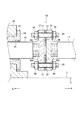
本発明の第1実施形態について図1から図4を参照して説明する。なお、図中、「L」は、左方向、「R」は、右方向をそれぞれ指している。
本発明の第2実施形態について図5から図7(a)(b)を参照して説明する。図中、「L」は、左方向、「R」は、右方向をそれぞれ指している。
1 加振装置
3 支持フレーム
5 テーブルベース
7 ガイド溝
9 スライドテーブル
11 スライド
15 テーブル
17 連結ロッド
19 静圧案内ユニット
21 静圧パッド
23 油圧シリンダ
39 ピストンロッド
51 往動用油圧室
53 復動用油圧室
53 軸継手
55 テーブル側継手部材
57 シリンダ側継手部材
59 頭無しボルト
61 ナット
63 ナット
65 凹球面座金
65f 凹球面座金の凹球面
69 凸球面座金
69f 凸球面座金の凸球面
73 加振装置
75 連結ロッド
77 連結ロッド
79 油圧シリンダ
81 油圧シリンダ
83 軸継手
85 軸継手
Claims (3)
- 被加振体を正逆方向へ加振させる加振装置において、
テーブルベースと、
前記テーブルベースに前記正逆方向へ往復移動可能に設けられ、一側に前記正逆方向に平行な連結ロッドを備え、前記被加振体を装備するスライドテーブルと、
前記テーブルベースに設けられ、前記スライドテーブルを前記正逆方向へ往復移動可能に案内する案内機構と、
前記スライドテーブルの一側方に設けられ、前記正逆方向に平行であってかつ前記正逆方向へ往復移動可能な作動ロッドを備え、前記スライダを前記正逆方向へ往復移動させる加振アクチュエータと、
前記連結ロッドの先端部と前記作動ロッドの先端部とを接続する軸継手と、を具備し、
前記軸継手は、
前記連結ロッドの先端部に一体的に設けられたテーブル側継手部材と、
前記作動ロッドの先端部に一体的に設けられ、複数のボルト及び複数のナットによって前記テーブル側継手部材に締結可能なアクチュエータ側継手部材と、
前記テーブル側継手部材の締結面と前記アクチュエータ側継手部材の締結面との間に配設され、前記ボルトを遊嵌可能な複数の貫通穴が円周方向に間隔を置いて形成され、片側に凹球面を有した凹球面座金と、
前記アクチュエータ側継手部材の締結面又は前記テーブル側継手部材の締結面と前記凹球面座金の前記凹球面との間に配設され、前記ボルトを遊嵌可能な複数の貫通穴が円周方向に間隔を置いて形成され、片側に前記凹球面座金の前記凹球面に摺接可能な凸球面を有した凸球面座金と、を備えたことを特徴とする加振装置。 - 被加振体を正逆方向へ加振させる加振装置において、
テーブルベースと、
前記テーブルベースに前記正逆方向へ往復移動可能に設けられ、両側に前記正逆方向に平行な連結ロッドを同軸状に備え、前記被加振体を装備するスライドテーブルと、
前記テーブルベースに設けられ、前記スライドテーブルを前記正逆方向へ往復移動可能に案内する案内機構と、
前記スライドテーブルの両側方にそれぞれ設けられ、前記正逆方向に平行でかつ前記正逆方向へ往復移動可能な作動ロッドを備え、前記スライダを前記正逆方向へ往復移動させる加振アクチュエータと、
各連結ロッドの先端部と対応する前記作動ロッドの先端部とを接続する軸継手と、を具備し、
各軸継手は、
前記連結ロッドの先端部に一体的に設けられたテーブル側継手部材と、
前記作動ロッドの先端部に一体的に設けられ、複数のボルト及び複数のナットによって前記テーブル側継手部材に締結可能なアクチュエータ側継手部材と、
前記テーブル側継手部材の締結面と前記アクチュエータ側継手部材の締結面との間に配設され、前記ボルトを遊嵌可能な複数の貫通穴が円周方向に間隔を置いて形成され、片側に凹球面を有した凹球面座金と、
前記アクチュエータ側継手部材の締結面又は前記テーブル側継手部材の締結面と前記凹球面座金の前記凹球面との間に配設され、前記ボルトを遊嵌可能な複数の貫通穴が円周方向に間隔を置いて形成され、片側に前記凹球面座金の前記凹球面に摺接可能な凸球面を有した凸球面座金と、を備えたことを特徴とする加振装置。 - 前記案内機構は、支持流体の静圧を利用して前記スライドテーブルを前記正逆方向へ往復移動可能に案内する静圧案内ユニッである請求項1又は請求項2に記載の加振装置。
Priority Applications (1)
| Application Number | Priority Date | Filing Date | Title |
|---|---|---|---|
| JP2012000141A JP5910085B2 (ja) | 2012-01-04 | 2012-01-04 | 加振装置 |
Applications Claiming Priority (1)
| Application Number | Priority Date | Filing Date | Title |
|---|---|---|---|
| JP2012000141A JP5910085B2 (ja) | 2012-01-04 | 2012-01-04 | 加振装置 |
Publications (2)
| Publication Number | Publication Date |
|---|---|
| JP2013140068A JP2013140068A (ja) | 2013-07-18 |
| JP5910085B2 true JP5910085B2 (ja) | 2016-04-27 |
Family
ID=49037622
Family Applications (1)
| Application Number | Title | Priority Date | Filing Date |
|---|---|---|---|
| JP2012000141A Active JP5910085B2 (ja) | 2012-01-04 | 2012-01-04 | 加振装置 |
Country Status (1)
| Country | Link |
|---|---|
| JP (1) | JP5910085B2 (ja) |
Families Citing this family (3)
| Publication number | Priority date | Publication date | Assignee | Title |
|---|---|---|---|---|
| EP3404394B1 (en) | 2016-01-15 | 2023-11-22 | Kokusai Keisokuki Kabushiki Kaisha | Vibration application device |
| JP7130221B2 (ja) * | 2016-06-30 | 2022-09-05 | 国際計測器株式会社 | 加振装置 |
| US10465746B2 (en) * | 2017-02-22 | 2019-11-05 | Team Corporation | Vibration test fixture |
Family Cites Families (4)
| Publication number | Priority date | Publication date | Assignee | Title |
|---|---|---|---|---|
| JPS57129920A (en) * | 1981-02-04 | 1982-08-12 | Hitachi Ltd | Joint of static pressure bearing type |
| US4602555A (en) * | 1984-02-01 | 1986-07-29 | Mts Systems Corporation | Preloaded table coupling |
| US4749300A (en) * | 1987-01-20 | 1988-06-07 | Maxon Corporation | Multi-functional reciprocating shaft coupling apparatus |
| JP2001304334A (ja) * | 2000-04-26 | 2001-10-31 | Mitsubishi Heavy Ind Ltd | ベアリング |
-
2012
- 2012-01-04 JP JP2012000141A patent/JP5910085B2/ja active Active
Also Published As
| Publication number | Publication date |
|---|---|
| JP2013140068A (ja) | 2013-07-18 |
Similar Documents
| Publication | Publication Date | Title |
|---|---|---|
| JP5910085B2 (ja) | 加振装置 | |
| US9158083B2 (en) | Ultrasonic motor and lens apparatus including the same | |
| US10363597B2 (en) | R-θ table apparatus and processing apparatus of internal thread | |
| JP5401693B2 (ja) | 中ぐり加工装置 | |
| JP5734025B2 (ja) | 加工装置 | |
| CN103661349B (zh) | 带有马达轴轴承的车辆制动系统的液压设备 | |
| JP5910086B2 (ja) | 加振装置 | |
| JP5880047B2 (ja) | 加振装置 | |
| JP2019066431A (ja) | 治具ユニット、試験装置および試験方法 | |
| JP2015152155A (ja) | 回動−線状軌跡往復動変換機構およびコンプレッサ | |
| JP5035123B2 (ja) | 油静圧スライド装置 | |
| JP2011002047A (ja) | ボールねじ式駆動装置 | |
| JP2013078230A5 (ja) | ||
| JP6685120B2 (ja) | ウォータージェット加工装置 | |
| KR102570667B1 (ko) | 체결용 가압 장치 | |
| KR200500121Y1 (ko) | 테이블형 블럭 실린더 | |
| US7267042B2 (en) | Hydraulic motor with telescopic propulsion members retained sealingly against associated contact surfaces by internal resilient means | |
| JP6601170B2 (ja) | 線形摩擦接合装置及び加振治具 | |
| JP7682732B2 (ja) | 往復ポンプ用の継手装置 | |
| KR101892068B1 (ko) | 로드의 회전방지기능을 갖는 실린더 장치 | |
| JP2014057397A (ja) | 超音波モータ | |
| US753367A (en) | No model | |
| US732713A (en) | Steam-pump. | |
| US1472753A (en) | Oil-distributing device | |
| JP6374415B2 (ja) | エアシリンダ、砥石保持装置および超仕上装置 |
Legal Events
| Date | Code | Title | Description |
|---|---|---|---|
| A621 | Written request for application examination |
Free format text: JAPANESE INTERMEDIATE CODE: A621 Effective date: 20141120 |
|
| A977 | Report on retrieval |
Free format text: JAPANESE INTERMEDIATE CODE: A971007 Effective date: 20150605 |
|
| A131 | Notification of reasons for refusal |
Free format text: JAPANESE INTERMEDIATE CODE: A131 Effective date: 20150616 |
|
| A521 | Written amendment |
Free format text: JAPANESE INTERMEDIATE CODE: A523 Effective date: 20150810 |
|
| TRDD | Decision of grant or rejection written | ||
| A01 | Written decision to grant a patent or to grant a registration (utility model) |
Free format text: JAPANESE INTERMEDIATE CODE: A01 Effective date: 20160301 |
|
| A61 | First payment of annual fees (during grant procedure) |
Free format text: JAPANESE INTERMEDIATE CODE: A61 Effective date: 20160314 |
|
| R151 | Written notification of patent or utility model registration |
Ref document number: 5910085 Country of ref document: JP Free format text: JAPANESE INTERMEDIATE CODE: R151 |
|
| R250 | Receipt of annual fees |
Free format text: JAPANESE INTERMEDIATE CODE: R250 |
|
| R250 | Receipt of annual fees |
Free format text: JAPANESE INTERMEDIATE CODE: R250 |