JP5919002B2 - Cutting equipment - Google Patents
Cutting equipment Download PDFInfo
- Publication number
- JP5919002B2 JP5919002B2 JP2012009809A JP2012009809A JP5919002B2 JP 5919002 B2 JP5919002 B2 JP 5919002B2 JP 2012009809 A JP2012009809 A JP 2012009809A JP 2012009809 A JP2012009809 A JP 2012009809A JP 5919002 B2 JP5919002 B2 JP 5919002B2
- Authority
- JP
- Japan
- Prior art keywords
- cutting
- cutting blade
- groove
- blade
- workpiece
- Prior art date
- Legal status (The legal status is an assumption and is not a legal conclusion. Google has not performed a legal analysis and makes no representation as to the accuracy of the status listed.)
- Active
Links
Images


Landscapes
- Constituent Portions Of Griding Lathes, Driving, Sensing And Control (AREA)
- Grinding-Machine Dressing And Accessory Apparatuses (AREA)
- Mechanical Treatment Of Semiconductor (AREA)
Description
本発明は、切削ブレードの偏磨耗を監視し、偏磨耗量が所定量以上となった場合には、先端形状を修正する機能を有する切削装置に関する。 The present invention relates to a cutting apparatus that monitors the uneven wear of a cutting blade and has a function of correcting a tip shape when the amount of uneven wear becomes a predetermined amount or more.
外周部が面取りされているウェーハの一方の面を研削すると、外周部が鋭角になり、その部分を起点として割れや欠けが生じることがあるため、かかるウェーハについては、研削前に、ウェーハの外周に沿って面取り部を円形に除去することが行われている。また、ウェーハの径を変更する場合も、外周に沿って円形に切り落とすことが行われている。このようにウェーハの外周に沿って切削することは、エッジトリミングと呼ばれている。 Grinding one side of a wafer with a chamfered outer periphery results in an acute angle at the outer periphery, which may cause cracks and chipping from that point. The chamfered portion is removed in a circular shape along the line. In addition, when changing the diameter of the wafer, it is cut into a circle along the outer periphery. Cutting along the outer periphery of the wafer in this way is called edge trimming.
ウェーハの外周に沿って円形に切削加工するエッジトリミングは、回転する切削ブレードをウェーハの外周に接触させるとともにウェーハを保持した保持テーブルを回転させ、切削ブレードの厚さを利用して先端面でウェーハ外周を切削することにより行われている(例えば特許文献1参照)。 Edge trimming, which cuts in a circle along the outer periphery of the wafer, contacts the outer periphery of the wafer with a rotating cutting blade and rotates the holding table that holds the wafer. This is done by cutting the outer periphery (see, for example, Patent Document 1).
しかし、エッジトリミング時においては、切削ブレードのウエーハ中心側とウエーハ外周側とでは、回転中心からの半径が異なるため、ウエーハ中心側とウエーハ外周側とで加工距離に違いがあるとともに、回転角度にも違いがある。そのため、切削ブレードのウエーハ中心側とウエーハ外周側とで摩耗量に差が生じてしまい、その摩耗差によって正常なエッジトリミング加工ができなくなるという問題がある。このように、切削ブレードに偏摩耗が生じた場合は、それを検出して加工不良を防止するとともに、偏摩耗が所定量以上に進行した場合は、切削ブレードの先端形状を整形する必要がある。 However, at the time of edge trimming, the radius from the rotation center differs between the wafer center side of the cutting blade and the wafer outer peripheral side, so there is a difference in processing distance between the wafer center side and the wafer outer peripheral side, and the rotation angle is also different. There is also a difference. For this reason, there is a problem in that the wear amount differs between the wafer center side of the cutting blade and the wafer outer peripheral side, and normal edge trimming cannot be performed due to the wear difference. As described above, when uneven wear occurs in the cutting blade, it is detected to prevent machining defects, and when the uneven wear proceeds to a predetermined amount or more, it is necessary to shape the tip shape of the cutting blade. .
本発明は、このような問題にかんがみなされたもので、切削ブレードの偏摩耗を監視するとともに、偏摩耗量が所定量以上となった場合には切削ブレードの先端形状を整形するようにすることを課題とする。 The present invention has been considered in view of such a problem, and monitors the uneven wear of the cutting blade, and shapes the tip shape of the cutting blade when the uneven wear amount exceeds a predetermined amount. Is an issue.
本発明は、円形の被加工物を保持し回転可能な保持手段と、保持手段に保持された被加工物を切削する切削ブレードを有する切削手段と、保持手段に保持される被加工物の外周縁を撮像する撮像手段と、切削ブレードが取り付けられる切削ブレード取付け面に平行な切削送り方向に保持手段と切削手段とを相対移動させる切削送り手段と、切削送り方向に直交する割り出し送り方向に保持手段と切削手段とを相対移動させる割り出し送り手段と、保持手段の保持面に垂直な方向である切り込み送り方向に保持手段と切削手段とを相対移動させる切り込み送り手段と、を少なくとも備える切削装置に関するもので、保持手段に隣接する位置に配設され、切削ブレードを切り込ませて切削ブレードの先端の偏磨耗の確認に用いる確認用被加工物を保持する確認テーブルと、
保持手段又は確認テーブルに隣接する位置に配設され、回転するとともに割り出し送り方向に移動する切削ブレードの先端を接触させて切削ブレードの先端を研磨する研磨テーブルと、確認テーブルが保持した確認用被加工物に対して切削ブレードを切り込み方向に所定量移動させて切り込ませることにより略長方形の切り込み溝を形成するとともに、切り込み溝が形成された時の切削手段の切り込み位置を切り込み位置記憶部に記憶する溝形成手段と、撮像手段が切り込み溝を撮像することにより取得した画像情報より、確認用被加工物の表面における切削送り方向を長手方向とする切り込み溝の向かい合う2辺の長さと切込み溝の溝幅中心での切り込み溝の長さとのそれぞれの差及び該向かい合う2辺の長さの差を求め、これらのそれぞれの差がそれぞれの所定の許容値をすべて超えている否かによって切り込み溝の良否判定を行う溝良否判断手段と、溝良否判断手段が切り込み溝が不良と判断したときに、切削ブレードを回転させつつ切削ブレードの先端を研磨テーブルに当接させ、切削手段と研磨テーブルとを割り出し送り手段にて所定量相対移動させて切削ブレードの先端形状を修正するブレード先端修正手段とを備える。
The present invention relates to a holding means capable of holding and rotating a circular workpiece, a cutting means having a cutting blade for cutting the workpiece held by the holding means, and an outside of the workpiece held by the holding means. Imaging means for imaging the periphery, cutting feed means for relatively moving the holding means and the cutting means in a cutting feed direction parallel to a cutting blade mounting surface to which the cutting blade is attached, and holding in an index feed direction orthogonal to the cutting feed direction The present invention relates to a cutting apparatus comprising at least indexing feeding means for relatively moving the means and the cutting means, and cutting feed means for relatively moving the holding means and the cutting means in a cutting feed direction that is a direction perpendicular to the holding surface of the holding means. A work piece for confirmation, which is disposed at a position adjacent to the holding means, and used for confirming uneven wear at the tip of the cutting blade by cutting the cutting blade. And confirmation table to equity,
A polishing table that is disposed at a position adjacent to the holding means or the check table and that contacts the tip of the cutting blade that rotates and moves in the indexing feed direction to polish the tip of the cutting blade, and a check target held by the check table By moving the cutting blade by a predetermined amount in the cutting direction with respect to the workpiece, a substantially rectangular cut groove is formed, and the cut position of the cutting means when the cut groove is formed is stored in the cut position storage unit. The groove forming means to be memorized, and the image information acquired by imaging the cutting groove by the imaging means, the length of the two opposite sides of the cutting groove with the cutting feed direction on the surface of the work piece for confirmation as the longitudinal direction and the cutting groove It obtains each difference and the difference in length of the opposing two sides of the length of the notches in the groove width center of it of The difference groove acceptability determining means for performing a quality determination of the cut recess depending on whether it exceeds all respective predetermined allowable value, when a groove cut groove acceptability determining means determines that the failure to rotate the cutting blade The blade tip correction means corrects the tip shape of the cutting blade by bringing the tip of the cutting blade into contact with the polishing table and relatively moving the cutting means and the polishing table by a predetermined amount by the indexing and feeding means.
上記切削装置においては、確認テーブルにおける確認用被加工物を保持する保持面の高さ位置であるテーブル高さと、切り込み溝の向かい合う2辺の長さの平均値と、切り込み位置記憶部に記憶されている切り込み溝を形成した時の切削手段の切り込み位置とを用い、切削ブレードの外径を算出するブレード外形算出部を備えることが望ましい。 In the cutting apparatus, the table height, which is the height position of the holding surface that holds the workpiece to be confirmed in the confirmation table, the average value of the lengths of the two sides facing the cut groove, and the cut position storage unit are stored. It is desirable to provide a blade outer shape calculation unit that calculates the outer diameter of the cutting blade using the cutting position of the cutting means when the cut groove is formed.
本発明は、切削ブレードを切り込ませて磨耗の確認に用いる確認用被加工物を保持する確認テーブルと、切削ブレードを接触させてその先端を研磨する研磨テーブルとを備え、確認用被加工物に形成した切り込み溝を撮像してその良否判定を行い、不良と判定したときには研磨テーブルを用いて切削ブレードの先端を研磨してその先端形状を修正することとしたため、被加工物の切削加工において加工不良が生じるのを防ぐことができる。 The present invention comprises a confirmation table for holding a confirmation workpiece used for confirming wear by cutting a cutting blade, and a polishing table for contacting the cutting blade and polishing the tip thereof. In the cutting process of the workpiece, the cutting groove formed in the image is imaged to determine its quality, and when it is determined to be defective, the tip of the cutting blade is polished using a polishing table to correct the tip shape. Processing defects can be prevented from occurring.
また、切削ブレードの外径を算出するブレード外形算出部を備えることで、切削ブレードの磨耗量を求めることができ、磨耗量を考慮して被加工物を切削することができる。 Further, by providing a blade outer shape calculating unit that calculates the outer diameter of the cutting blade, the amount of wear of the cutting blade can be obtained, and the workpiece can be cut in consideration of the amount of wear.
図1に示す切削装置1は、保持手段2に保持された被加工物に対して2つの切削手段3a、3bによって切削加工を施す装置であり、これらは互いに相対的に切削送り方向(X軸方向)、切削送り方向に直交する割り出し送り方向(Y軸方向)、及び、切削送り方向及び割り出し送り方向に直交する切り込み送り方向(Z軸方向)に移動可能となっている。図1の例では、保持手段2が切削送り手段4によって駆動されてX軸方向に移動し、切削手段3a、3bが割り出し送り手段5及び切り込み送り手段6によって駆動されてY軸方向およびZ軸方向に移動する構成としているが、この構成には限定されない。
A
保持手段2は、例えば多孔質部材によって形成され円形の被加工物を保持する保持部材20を備えている。保持部材20は、図示しない吸引源に連通している。
The
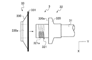
図2に示すように、切削手段3a、3bは、Y軸方向の軸心を有するスピンドル31の先端にマウント32が装着され、マウント32に切削ブレード33が装着されて構成されている。マウント32は、切削ブレード33を面で支持するフランジ部320と、切削ブレード33が挿入されるブレード挿入部321とから構成され、ブレード挿入部321には、切削ブレード33を固定するためのナットを螺着させる雄ねじ321aが形成されている。
As shown in FIG. 2, the cutting means 3 a and 3 b are configured such that a
切削ブレード33は、ブレード挿入部321に挿入するための貫通孔330aが中心部に形成された基台330と、基台330から外周側に突出した状態で固着された切り刃331とから構成され、切削ブレード33をブレード挿入孔321に挿入し、図示しないナットを雄ねじ321aに螺着させると、切り刃331が、フランジ部320の切削ブレード取り付け面320aに密着して面で支持される。ブレード取り付け面320aは、X軸方向に対して平行となっている。
The
図1に示すように、切削送り手段4は、X軸方向に延びるボールスクリュー40と、ボールスクリュー40と平行に配設された一対のガイドレール41と、ボールスクリュー40の一端に連結されたモータ42と、ボールスクリュー40に螺合するナットを内部に有するとともに下部がガイドレール41に摺接する移動基台43とから構成され、モータ42に駆動されてボールスクリュー40が回動するのにともない、ガイドレール41にガイドされて移動基台43がX軸方向に移動する構成となっている。また、移動基台43の上には保持手段2が設けられており、移動基台43の移動によって保持手段2も同方向に移動する。
As shown in FIG. 1, the cutting feed means 4 includes a
割り出し送り手段5は、Y軸方向に延びるボールスクリュー50と、ボールスクリュー50と平行に配設された一対のガイドレール51と、ボールスクリュー50の一端に連結されたモータ52と、ボールスクリュー50に螺合するナットを内部に有するとともに側部がガイドレール51に摺接する移動基台53とから構成され、モータ52に駆動されてボールスクリュー50が回動するのにともない、ガイドレール51にガイドされて移動基台53がX軸方向に移動する構成となっている。また、移動基台53には、切り込み送り手段6を介して切削手段3a、3bが設けられており、移動基台53の移動によって切削手段3も同方向に移動する。
The index feeding means 5 includes a ball screw 50 extending in the Y-axis direction, a pair of guide rails 51 arranged in parallel to the ball screw 50, a
切り込み送り手段6は、Z軸方向に延びるボールスクリュー60と、ボールスクリュー60と平行に配設された一対のガイドレール61と、ボールスクリュー60の一端に連結されたモータ62と、ボールスクリュー60に螺合するナットを内部に有するとともに側部がガイドレール61に摺接する移動基台63とから構成され、モータ62に駆動されてボールスクリュー60が回動するのにともない、ガイドレール61にガイドされて移動基台63がX軸方向に移動する構成となっている。また、移動基台63の下端では切削手段3a、3bをそれぞれ支持しており、移動基台63の昇降によって切削手段3a、3bもそれぞれ同方向に昇降する。
The cutting feed means 6 includes a
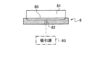
図1に示すように、移動基台43上には、保持手段2に隣接する位置に確認テーブル8を備えている。確認テーブル8の上面である保持面80には、図3及び図4に示すように、確認用被加工物81が保持される。確認テーブル8の内部には吸引路82が形成され、吸引路82は吸引源83に連通しており、保持面80において吸引力を作用させることにより確認用被加工物81を吸引保持することができる。この確認用被加工物81は、切削手段3を構成する切削ブレード31を切り込ませることにより、切削ブレード31の先端の偏磨耗を確認するのに用いられる。
As shown in FIG. 1, a confirmation table 8 is provided on the moving
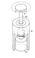
図1に示す移動基台43上には、保持手段2又は確認テーブル8に隣接する位置において研磨テーブル9が配設されている。研磨テーブル9は、回転するとともに割り出し送り方向に移動する切削ブレード31の先端を接触させて切削ブレードの先端を研磨するのに用いる。図5に示すように、研磨テーブル9は、回転軸90に連結され、この回転軸90は、カップリング91によってモータ92の回転軸に連結されており、モータ92に駆動されて研磨テーブル9が回転する構成となっている。
On the moving
図1に示すように、切り込み送り手段6を構成するモータ62及び切削手段3a、3bには、溝形成手段10が接続されている。溝形成手段10は、切削ブレード33を回転させるとともに、切削ブレード33を確認用被加工物81に切り込ませることにより、確認用被加工物に切り込み溝を形成する。この切り込み溝は、切削ブレード33の切り刃331の先端の磨耗の有無及び程度を判断するためのものである。溝形成手段10は、切り込み溝が形成された時の切削手段3aの切り込み方向の位置(切り込み位置)、具体的には、切削ブレード33の回転中心のZ軸方向の位置を切り込み位置記憶部15に記憶する。
As shown in FIG. 1, the
切削手段3a、3bの側部には、下方を撮像する撮像手段7a、7bが固定されており、撮像手段7a、7bには、溝良否判断手段11が接続されている。溝良否判断手段11は、CPU、メモリ等を有しており、撮像手段7a、7bが上記切り込み溝を撮像し取得した画像情報から、切り込み溝の形状の良否、すなわち切削ブレード31の先端形状の良否の判定を行う機能を有する。
Imaging means 7a and 7b for imaging the lower part are fixed to the side portions of the cutting means 3a and 3b, and a groove quality determination means 11 is connected to the imaging means 7a and 7b. The groove quality determination means 11 includes a CPU, a memory, and the like. From the image information acquired by the imaging means 7a and 7b imaging the cut groove, the quality of the cut groove shape, that is, the tip shape of the
ブレード外径算出部12は、確認用被加工物81に形成した切り込み溝の長さ、前記切り込み位置記憶部15に記憶された切り込み送り手段6の切り込み位置等に基づき、切削ブレード33の外径を算出する機能を有する。
The blade outer
ブレード先端修正手段13は、溝良否判断手段11が切り込み溝を不良と判断したときに、切削ブレード31を回転させて切り刃331の先端を研磨テーブル9に当接させることにより、先端形状を修正する機能を有する。
The blade tip correcting means 13 corrects the tip shape by rotating the
テーブル位置記憶部14は、確認テーブル8の保持面80の高さ位置であるテーブル高さを記憶するとともに、切削ブレード33の切り刃331の先端とテーブル高さとの距離を記憶する。
The table
以下では、図1に示した保持手段2において円形の被加工物を保持し、切削手段3aを構成する切削ブレード33を用いて、被加工物の外周に沿って切削ブレード33を切り込ませて切削加工を行う場合について説明する。
In the following, the circular workpiece is held by the holding means 2 shown in FIG. 1, and the
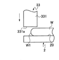
図6に示すように、保持手段2に保持された被加工物Wは、外周に面取り部W1が形成されている。最初に撮像手段7aを移動させながら被加工物Wの撮像を行い、被加工物Wの外周縁に形成された面取り部W1を検出する。そして、面取り部W1が検出されると、切削ブレード33を回転させながら面取り部W1の上方に位置させる。
As shown in FIG. 6, the workpiece W held by the holding means 2 has a chamfered portion W1 formed on the outer periphery. First, the workpiece W is imaged while moving the imaging means 7a, and the chamfered portion W1 formed on the outer peripheral edge of the workpiece W is detected. When the chamfered portion W1 is detected, the
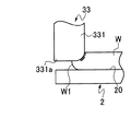
次に、保持手段2を回転させるとともに、回転する切削ブレード33を下降させ、図7に示すように、面取り部W1に切削ブレード33の切り刃331の先端部331aを接触させる。そうすると、面取り部W1が円形に除去されてエッジトリミングが行われるとともに、切り刃331の先端部331aが磨耗する。図7に示すように、先端部331aの半分のみを面取り部W1に接触させた場合は、先端部331aの接触した半分のうち、接触時間の長い部分が多く磨耗し、左右が非対称の形状となる。
Next, while rotating the holding means 2, the
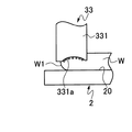
一方、図8に示すように、先端部331aのほぼ全体を面取り部W1に接触させた場合は、被加工物Wの中心側(図8における右側)と外周側(図8における左側)とで加工距離に違いがあり、接触時間の長い部分が多く磨耗するため、先端部331aの中心が窪んだ形状に磨耗する。
On the other hand, as shown in FIG. 8, when almost the
このように、切削ブレード33の切り刃331の先端部331aが磨耗した場合は、そのまま切削加工を続行すると、切削不良を起こすおそれがあるため、先端部331aの整形を行う。
As described above, when the
具体的には、図1に示した溝形成手段10による制御の下で、図9(a)に示すように、移動基台43をX軸方向に移動させるとともに、整形の必要のある切削ブレード33を有する切削手段、例えば切削手段3aをY軸方向に移動させ、確認テーブル80に保持された確認用被加工物81の直上に切削ブレード33を位置させる。
Specifically, under the control of the groove forming means 10 shown in FIG. 1, as shown in FIG. 9A, the moving
そして、図9(b)に示すように、回転する切削ブレード33をZ軸方向に所定量下降させて先端部331aを確認用被加工物81に切り込ませ、その後上昇させることにより、図9(c)に示すように、確認用被加工物81の表面に、X軸方向を長手方向とする略長方形の切り込み溝810を形成する。なお、確認用被加工物81としては、被加工物Wと同じ材質のものが使用される。例えば、被加工物Wがシリコンウェーハである場合は、確認用被加工物としてシリコンピースが使用される。
Then, as shown in FIG. 9B, the
次に、切削ブレード33の下方から確認用被加工物81を退避させ、図9(d)に示すように、切り込み溝810の上方に、いずれかの撮像手段、例えば、切削に使用していない切削手段3bに固定された撮像手段3bを移動させる。そして、撮像手段3bによって切り込み溝810を撮像し、その画像情報を図1に示した溝良否判断手段11に転送する。
Next, the
溝良否判断手段11では、図10に示すように、切り込み溝810の向かい合う2つの長辺の長さa、bと、切り込み溝810の溝幅Wの中心における切り込み溝810の長さcとを画像処理によって求める。そして、|a−b|、|a−c|、|c−b|の値をそれぞれ計算する。図11に示す切り込み溝810aのように、幅方向の中心部が短く形成されている場合等も、同様の計算を行う。
As shown in FIG. 10, the groove pass / fail judgment means 11 determines the lengths a and b of the two long sides facing the
溝良否判定手段11に備えたメモリには、上記|a−b|、|a−c|、|c−b|の値の所定の許容値Xab、Xac、Xcbがあらかじめ記憶されており、溝良否判定手段11では、|a−b|とXab、|a−c|とXac、|c−b|とXcbをそれぞれ比較し、以下の関係式(1)〜(3)が成り立つと判断したときには、先端部331aの磨耗が許容範囲を超えており、先端部331aの整形を要すると判断する。
Xab<|a−b| ・・・関係式(1)
Xac<|a−c| ・・・関係式(2)
Xcb<|c−b| ・・・関係式(3)
In the memory provided in the groove pass / fail judgment means 11, predetermined allowable values Xab, Xac, Xcb of the values of | a−b |, | a−c |, | c−b | The pass / fail judgment means 11 compares | a−b | and Xab, | a−c | and Xac, and | c−b | and Xcb, respectively, and determines that the following relational expressions (1) to (3) hold. Sometimes, it is determined that the wear of the
Xab <| a−b |... Relational expression (1)
Xac <| ac− | Relational expression (2)
Xcb <| c−b |... Relational expression (3)
上記関係式(1)〜(3)がすべて成立する場合は、図1に示したブレード先端修正手段13による制御の下で、切削ブレード33の切り刃331の先端部331aを整形し、形状を修正する。具体的には、切削ブレード33を図1及び図5に示した研磨テーブル9の上方に移動させ、図12に示すように、切削ブレード33を回転させつつ切削ブレード33の先端部331aを研磨テーブル9に当接させ、切削手段3aを割り出し送り手段5によって所定量Y軸方向に移動させて切削手段3aと研磨テーブル9とをY軸方向に所定量相対移動させることで、切削ブレード33の先端部331aを研磨してその形状を修正し、切削ブレード33を上昇させる。その後、研磨テーブル9を回転させることで、次の研磨が行われる際に、研磨テーブル9の未使用部分を用いて研磨を行うことができる。かかる修正により、切削ブレード33の先端部331aが円形に整形され、被加工物Wを切削できる状態となるため、被加工物Wの切削を再開する。以上のようにして切削ブレード33の先端部331aを研磨することにより、被加工物に加工不良が生じるのを防止することができる。
When all of the above relational expressions (1) to (3) hold, the
一方、いずれかの関係式が成立しない場合は、先端部331aの整形をすることなく被加工物Wの切削を行うが、いずれにしても、先端部331aの磨耗量を考慮して切削時の切り込み深さを調整することで、被加工物Wに対して所望の切削加工を行うことができる。
On the other hand, if any one of the relational expressions is not satisfied, the workpiece W is cut without shaping the
切削ブレード33の使用前の外径(半径)は、予めブレード外形算出部12に記憶されている。したがって、磨耗後の切削ブレード33の外径を算出すれば、摩耗量を求めることができ、磨耗量を考慮して切削ブレード33のZ軸方向の高さ位置を制御することにより、被加工物に対する切り込み量を均一にすることができる。
The outer diameter (radius) of the
撮像部7bによる撮像及び画像処理により、図13に示すように、切削ブレード33の先端部331aを確認用被加工物81に切り込ませた際に形成された切り込み溝810の長さLを求める。この切り込み溝810の長さLは、図10に示した2辺a,bの長さの平均値をとることが望ましい。
As shown in FIG. 13, the length L of the
また、確認テーブル8の保持面80と切削ブレード33の回転中心との距離Hは、テーブル位置記憶部14に記憶されているテーブル高さと、切り込み位置記憶部15に記憶された切削ブレード33の回転中心のZ軸方向の高さ位置との差から求められる。
The distance H between the holding
したがって、確認用被加工物の厚さをTとすると、切削ブレードの外径Rは、
(H−T)2+(L/2)2=R2
の関係式から算出することができる。そして、使用前の切削ブレード33の外径から算出した外径Rの値を引くことにより、先端部331aの磨耗量を算出することができ、切削手段3aの切り込み送り方向の位置を制御する際に、この磨耗量を考慮することで、被加工物に対して切削ブレード33を所望量切り込ませることができる。
Therefore, when the thickness of the workpiece to be confirmed is T, the outer diameter R of the cutting blade is
(HT) 2 + (L / 2) 2 = R 2
It can be calculated from the relational expression The amount of wear of the
1:切削装置
2:保持手段 20:保持手段
3a、3b:切削手段
31:スピンドル
32:マウント
320:フランジ部 320a:切削ブレード取り付け面
321:ブレード挿入部 321a:雄ねじ
33:切削ブレード 330:基台 330a:貫通孔 331:切り刃
4:切削送り手段
40:ボールスクリュー 41:ガイドレール 42:モータ 43:移動基台
5:割り出し送り手段
50:ボールスクリュー 51:ガイドレール 52:モータ 53:移動基台
6:切り込み送り手段
60:ボールスクリュー 61:ガイドレール 62:モータ 63:移動基台
7a、7b:撮像手段
8:確認テーブル
80:保持面 81:確認用被加工物
9:研磨テーブル 90:回転軸 91:カップリング 92:モータ
10:溝形成手段
11:溝良否判断手段
12:ブレード外径算出部
13:ブレード先端修正手段
14:テーブル位置記憶部
15:切り込み位置記憶部
1: Cutting device 2: Holding means 20: Holding means 3a, 3b: Cutting means 31: Spindle 32: Mount 320:
Claims (2)
該保持手段に隣接する位置に配設され、該切削ブレードを切り込ませて該切削ブレードの先端の偏磨耗の確認に用いる確認用被加工物を保持する確認テーブルと、
該保持手段又は該確認テーブルに隣接する位置に配設され、回転するとともに該割り出し送り方向に移動する該切削ブレードの先端を接触させて該切削ブレードの先端を研磨する研磨テーブルと、
該確認テーブルが保持した確認用被加工物に対して該切削ブレードを切り込み方向に所定量移動させて切り込ませることにより略長方形の切り込み溝を形成するとともに、該切り込み溝が形成された時の該切削手段の切り込み位置を切り込み位置記憶部に記憶する溝形成手段と、
該撮像手段が該切り込み溝を撮像することにより取得した画像情報より、該確認用被加工物の表面における該切削送り方向を長手方向とする該切り込み溝の向かい合う2辺の長さと該切込み溝の溝幅中心での該切り込み溝の長さとのそれぞれの差及び該向かい合う2辺の長さの差を求め、これらのそれぞれの差がそれぞれの所定の許容値をすべて超えているか否かによって該切り込み溝の良否判定を行う溝良否判断手段と、
該溝良否判断手段が該切り込み溝が不良と判断したときに、該切削ブレードを回転させつつ該切削ブレードの先端を該研磨テーブルに当接させ、該切削手段と該研磨テーブルとを割り出し送り手段にて所定量相対移動させて該切削ブレードの先端形状を修正するブレード先端修正手段と
を備える切削装置。 A holding means capable of holding and rotating a circular workpiece, a cutting means having a cutting blade for cutting the workpiece held by the holding means, and an outer peripheral edge of the workpiece held by the holding means. Imaging means for imaging, cutting feed means for relatively moving the holding means and the cutting means in a cutting feed direction parallel to a cutting blade mounting surface to which the cutting blade is attached, and an indexing feed direction orthogonal to the cutting feed direction An indexing feed means for relatively moving the holding means and the cutting means, and a cutting feed means for relatively moving the holding means and the cutting means in a cutting feed direction which is a direction perpendicular to the holding surface of the holding means. In a cutting device comprising at least
A confirmation table that is disposed at a position adjacent to the holding means and holds the workpiece to be used for confirming uneven wear at the tip of the cutting blade by cutting the cutting blade;
A polishing table disposed at a position adjacent to the holding means or the confirmation table and polishing the tip of the cutting blade by contacting the tip of the cutting blade rotating and moving in the indexing feed direction;
When the cutting blade is moved by a predetermined amount in the cutting direction and cut into the workpiece to be checked held by the checking table, a substantially rectangular cut groove is formed, and when the cut groove is formed Groove forming means for storing the cutting position of the cutting means in the cutting position storage unit;
From the image information acquired by the imaging means imaging the cut groove, the length of the two opposite sides of the cut groove on the surface of the work piece for confirmation, the cutting feed direction being the longitudinal direction, and the cut groove obtains each difference and the difference in length of the opposing two sides of the length of the notches in the groove width center, the by whether the difference of each of which exceeds all respective predetermined allowable value A groove quality judging means for judging the quality of the cut groove;
When the groove quality determining means determines that the cut groove is defective, the cutting blade is brought into contact with the polishing table while rotating the cutting blade, and the cutting means and the polishing table are indexed and fed. And a blade tip correcting means for correcting the tip shape of the cutting blade by moving the tip by a predetermined amount.
請求項1記載の切削装置。 The table height, which is the height position of the holding surface for holding the workpiece to be confirmed in the confirmation table, the average value of the lengths of the two opposite sides of the notch groove, and the notch stored in the notch position storage unit The cutting apparatus according to claim 1, further comprising a blade outer shape calculation unit that calculates an outer diameter of the cutting blade using a cutting position of the cutting means when the groove is formed.
Priority Applications (1)
| Application Number | Priority Date | Filing Date | Title |
|---|---|---|---|
| JP2012009809A JP5919002B2 (en) | 2012-01-20 | 2012-01-20 | Cutting equipment |
Applications Claiming Priority (1)
| Application Number | Priority Date | Filing Date | Title |
|---|---|---|---|
| JP2012009809A JP5919002B2 (en) | 2012-01-20 | 2012-01-20 | Cutting equipment |
Publications (2)
| Publication Number | Publication Date |
|---|---|
| JP2013146831A JP2013146831A (en) | 2013-08-01 |
| JP5919002B2 true JP5919002B2 (en) | 2016-05-18 |
Family
ID=49044881
Family Applications (1)
| Application Number | Title | Priority Date | Filing Date |
|---|---|---|---|
| JP2012009809A Active JP5919002B2 (en) | 2012-01-20 | 2012-01-20 | Cutting equipment |
Country Status (1)
| Country | Link |
|---|---|
| JP (1) | JP5919002B2 (en) |
Families Citing this family (11)
| Publication number | Priority date | Publication date | Assignee | Title |
|---|---|---|---|---|
| JP6163916B2 (en) * | 2013-06-28 | 2017-07-19 | 株式会社ジェイテクト | Wheel wear measurement method |
| JP6139325B2 (en) * | 2013-08-07 | 2017-05-31 | 株式会社ディスコ | Cutting blade wear inspection method |
| JP6246566B2 (en) * | 2013-11-11 | 2017-12-13 | 株式会社ディスコ | Dressing method |
| JP6478794B2 (en) * | 2015-05-08 | 2019-03-06 | 株式会社ディスコ | Manufacturing method of angled cutting blade |
| JP6464028B2 (en) * | 2015-05-11 | 2019-02-06 | 株式会社ディスコ | Cutting blade outer diameter size detection method |
| JP6562725B2 (en) * | 2015-06-10 | 2019-08-21 | 株式会社ディスコ | Cutting equipment |
| JP2017196712A (en) * | 2016-04-28 | 2017-11-02 | 株式会社ディスコ | Cutting device |
| JP6732381B2 (en) * | 2016-10-03 | 2020-07-29 | 株式会社ディスコ | Cutting equipment |
| JP6648398B2 (en) * | 2018-09-10 | 2020-02-14 | 株式会社東京精密 | Blade diagnosis method, blade diagnosis device, blade tip shape calculation method, and blade tip shape calculation device |
| CN114746214B (en) * | 2019-12-03 | 2024-07-12 | 株式会社荏原制作所 | Grinding device and grinding method |
| JP7817091B2 (en) * | 2022-06-13 | 2026-02-18 | 株式会社ディスコ | Dressing Method |
Family Cites Families (4)
| Publication number | Priority date | Publication date | Assignee | Title |
|---|---|---|---|---|
| JPH05253837A (en) * | 1992-03-12 | 1993-10-05 | Sony Corp | Method of inspecting the wear state of the grindstone |
| US5718615A (en) * | 1995-10-20 | 1998-02-17 | Boucher; John N. | Semiconductor wafer dicing method |
| JP4401643B2 (en) * | 2002-11-12 | 2010-01-20 | 東芝機械株式会社 | Truing position calculation device and method, and truing method |
| JP2011249571A (en) * | 2010-05-27 | 2011-12-08 | Disco Abrasive Syst Ltd | Cutting blade outer shape inspection method |
-
2012
- 2012-01-20 JP JP2012009809A patent/JP5919002B2/en active Active
Also Published As
| Publication number | Publication date |
|---|---|
| JP2013146831A (en) | 2013-08-01 |
Similar Documents
| Publication | Publication Date | Title |
|---|---|---|
| JP5919002B2 (en) | Cutting equipment | |
| JP6242619B2 (en) | Processing equipment | |
| KR102251723B1 (en) | Cutting apparatus | |
| US10639811B2 (en) | Cutting apparatus | |
| KR20170123247A (en) | Method for manufacturing device and grinding apparatus | |
| JP6768185B2 (en) | Dicing method and equipment | |
| JP6953075B2 (en) | Cutting equipment and wafer processing method | |
| JP2021121031A (en) | Wafer positioning apparatus and chamfering apparatus using the same | |
| JP6791552B2 (en) | Cutting equipment | |
| JP2025130078A (en) | Method for grinding and turning a workpiece | |
| JP5762005B2 (en) | Processing position adjustment method and processing apparatus | |
| JP2024009097A (en) | Dicing equipment and dicing method | |
| JP7068096B2 (en) | Grinding method for workpieces | |
| JP4911810B2 (en) | Workpiece grinding apparatus and grinding method | |
| JP6457327B2 (en) | Setup method | |
| KR20150014868A (en) | Method of uniformizing chipping allowance and marginal grinder of plate material | |
| JP2009078326A (en) | Wafer chamfering device and wafer chamfering method | |
| JP6205231B2 (en) | Cutting equipment | |
| JP6828336B2 (en) | Processing method | |
| JP2021094693A (en) | Manufacturing method of chamfered baseboard and chamfering device used in the same | |
| CN113829529A (en) | Cutting device | |
| JP5679171B2 (en) | Dicing apparatus and dicing method | |
| JP2017163018A (en) | Wafer processing apparatus and wafer processing method | |
| JP2013149822A (en) | Edge trimming method | |
| JP2016186958A (en) | Dicing device and dicing method by dicing device |
Legal Events
| Date | Code | Title | Description |
|---|---|---|---|
| A621 | Written request for application examination |
Free format text: JAPANESE INTERMEDIATE CODE: A621 Effective date: 20141224 |
|
| RD02 | Notification of acceptance of power of attorney |
Free format text: JAPANESE INTERMEDIATE CODE: A7422 Effective date: 20150427 |
|
| A977 | Report on retrieval |
Free format text: JAPANESE INTERMEDIATE CODE: A971007 Effective date: 20151028 |
|
| A131 | Notification of reasons for refusal |
Free format text: JAPANESE INTERMEDIATE CODE: A131 Effective date: 20151102 |
|
| A521 | Request for written amendment filed |
Free format text: JAPANESE INTERMEDIATE CODE: A523 Effective date: 20151224 |
|
| TRDD | Decision of grant or rejection written | ||
| A01 | Written decision to grant a patent or to grant a registration (utility model) |
Free format text: JAPANESE INTERMEDIATE CODE: A01 Effective date: 20160315 |
|
| A61 | First payment of annual fees (during grant procedure) |
Free format text: JAPANESE INTERMEDIATE CODE: A61 Effective date: 20160411 |
|
| R150 | Certificate of patent or registration of utility model |
Ref document number: 5919002 Country of ref document: JP Free format text: JAPANESE INTERMEDIATE CODE: R150 |
|
| R250 | Receipt of annual fees |
Free format text: JAPANESE INTERMEDIATE CODE: R250 |
|
| R250 | Receipt of annual fees |
Free format text: JAPANESE INTERMEDIATE CODE: R250 |
|
| R250 | Receipt of annual fees |
Free format text: JAPANESE INTERMEDIATE CODE: R250 |
|
| R250 | Receipt of annual fees |
Free format text: JAPANESE INTERMEDIATE CODE: R250 |
|
| R250 | Receipt of annual fees |
Free format text: JAPANESE INTERMEDIATE CODE: R250 |
|
| R250 | Receipt of annual fees |
Free format text: JAPANESE INTERMEDIATE CODE: R250 |
|
| R250 | Receipt of annual fees |
Free format text: JAPANESE INTERMEDIATE CODE: R250 |