JP5933403B2 - ディスク装置用サスペンション - Google Patents
ディスク装置用サスペンション Download PDFInfo
- Publication number
- JP5933403B2 JP5933403B2 JP2012214023A JP2012214023A JP5933403B2 JP 5933403 B2 JP5933403 B2 JP 5933403B2 JP 2012214023 A JP2012214023 A JP 2012214023A JP 2012214023 A JP2012214023 A JP 2012214023A JP 5933403 B2 JP5933403 B2 JP 5933403B2
- Authority
- JP
- Japan
- Prior art keywords
- microactuator
- metal base
- resin layer
- suspension
- gimbal
- Prior art date
- Legal status (The legal status is an assumption and is not a legal conclusion. Google has not performed a legal analysis and makes no representation as to the accuracy of the status listed.)
- Active
Links
Images


Classifications
-
- G—PHYSICS
- G11—INFORMATION STORAGE
- G11B—INFORMATION STORAGE BASED ON RELATIVE MOVEMENT BETWEEN RECORD CARRIER AND TRANSDUCER
- G11B5/00—Recording by magnetisation or demagnetisation of a record carrier; Reproducing by magnetic means; Record carriers therefor
- G11B5/48—Disposition or mounting of heads or head supports relative to record carriers ; arrangements of heads, e.g. for scanning the record carrier to increase the relative speed
- G11B5/4806—Disposition or mounting of heads or head supports relative to record carriers ; arrangements of heads, e.g. for scanning the record carrier to increase the relative speed specially adapted for disk drive assemblies, e.g. assembly prior to operation, hard or flexible disk drives
- G11B5/4826—Mounting, aligning or attachment of the transducer head relative to the arm assembly, e.g. slider holding members, gimbals, adhesive
- G11B5/483—Piezoelectric devices between head and arm, e.g. for fine adjustment
-
- G—PHYSICS
- G11—INFORMATION STORAGE
- G11B—INFORMATION STORAGE BASED ON RELATIVE MOVEMENT BETWEEN RECORD CARRIER AND TRANSDUCER
- G11B5/00—Recording by magnetisation or demagnetisation of a record carrier; Reproducing by magnetic means; Record carriers therefor
- G11B5/48—Disposition or mounting of heads or head supports relative to record carriers ; arrangements of heads, e.g. for scanning the record carrier to increase the relative speed
- G11B5/4806—Disposition or mounting of heads or head supports relative to record carriers ; arrangements of heads, e.g. for scanning the record carrier to increase the relative speed specially adapted for disk drive assemblies, e.g. assembly prior to operation, hard or flexible disk drives
- G11B5/4853—Constructional details of the electrical connection between head and arm
-
- G—PHYSICS
- G11—INFORMATION STORAGE
- G11B—INFORMATION STORAGE BASED ON RELATIVE MOVEMENT BETWEEN RECORD CARRIER AND TRANSDUCER
- G11B5/00—Recording by magnetisation or demagnetisation of a record carrier; Reproducing by magnetic means; Record carriers therefor
- G11B5/48—Disposition or mounting of heads or head supports relative to record carriers ; arrangements of heads, e.g. for scanning the record carrier to increase the relative speed
- G11B5/4806—Disposition or mounting of heads or head supports relative to record carriers ; arrangements of heads, e.g. for scanning the record carrier to increase the relative speed specially adapted for disk drive assemblies, e.g. assembly prior to operation, hard or flexible disk drives
- G11B5/484—Integrated arm assemblies, e.g. formed by material deposition or by etching from single piece of metal or by lamination of materials forming a single arm/suspension/head unit
-
- G—PHYSICS
- G11—INFORMATION STORAGE
- G11B—INFORMATION STORAGE BASED ON RELATIVE MOVEMENT BETWEEN RECORD CARRIER AND TRANSDUCER
- G11B5/00—Recording by magnetisation or demagnetisation of a record carrier; Reproducing by magnetic means; Record carriers therefor
- G11B5/48—Disposition or mounting of heads or head supports relative to record carriers ; arrangements of heads, e.g. for scanning the record carrier to increase the relative speed
- G11B5/4806—Disposition or mounting of heads or head supports relative to record carriers ; arrangements of heads, e.g. for scanning the record carrier to increase the relative speed specially adapted for disk drive assemblies, e.g. assembly prior to operation, hard or flexible disk drives
- G11B5/4873—Disposition or mounting of heads or head supports relative to record carriers ; arrangements of heads, e.g. for scanning the record carrier to increase the relative speed specially adapted for disk drive assemblies, e.g. assembly prior to operation, hard or flexible disk drives the arm comprising piezoelectric or other actuators for adjustment of the arm
Landscapes
- Supporting Of Heads In Record-Carrier Devices (AREA)
- Adjustment Of The Magnetic Head Position Track Following On Tapes (AREA)
- Moving Of The Head To Find And Align With The Track (AREA)
Description
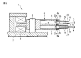
図1に示すディスク装置(HDD)1は、ケース2と、スピンドル3を中心に回転するディスク4と、ピボット軸5を中心に旋回可能なキャリッジ6と、キャリッジ6を駆動するためのポジショニング用モータ(ボイスコイルモータ)7などを有している。ケース2は、図示しない蓋によって密閉される。
ポジショニング用モータ7によってキャリッジ6(図1と図2に示す)が旋回すると、サスペンション10がディスク4の径方向に移動することにより、磁気ヘッドのスライダ11がディスク4の記録面の所望トラックまで移動する。マイクロアクチュエータ素子31,32に電圧が印加されると、電圧に応じてマイクロアクチュエータ素子31,32が互いに反対方向に歪むことにより、ロードビーム21をスウェイ方向(図3に矢印Yで示す方向)に微小量移動させることができる。
Claims (5)
- ロードビームと、
前記ロードビームに固定された固定側部分とスライダが配置されるジンバル部とを有するフレキシャと、
前記ジンバル部に搭載されたマイクロアクチュエータ素子と、
を具備したディスク装置用サスペンションであって、
前記マイクロアクチュエータ素子は、
第1および第2の端面を有した素子本体と、
前記素子本体の少なくとも一方の端面を覆う電極とを有し、
前記ジンバル部は、
金属からなるメタルベースと、
前記メタルベース上に設けられた電気絶縁性の樹脂層と、
前記樹脂層の厚さ方向に重ねて配置された導体と、
前記マイクロアクチュエータ素子の端部を前記メタルベースに固定する電気絶縁性接着材と、
前記マイクロアクチュエータ素子の前記電極と前記導体との間に設けた導電性ペーストと、
前記メタルベースと前記導電性ペーストとの間において前記樹脂層の厚さ方向に沿って前記樹脂層と前記電気絶縁性接着材とが接着した第1の接着界面と、
前記メタルベースと前記導電性ペーストとの間において前記樹脂層の面方向に沿って前記樹脂層と前記電気絶縁性接着材とが接着した第2の接着界面と、
前記第1の接着界面と前記第2の接着界面とが交わる箇所に形成されたコーナー部と、
を具備したことを特徴とするディスク装置用サスペンション。 - 前記ジンバル部の前記メタルベースに形成された開口と、
前記開口に収容された前記マイクロアクチュエータ素子と、
前記開口の少なくとも一部を覆って前記メタルベースに固定され、前記マイクロアクチュエータ素子を支持するダンパ部材と、
を具備したことを特徴とする請求項1に記載のディスク装置用サスペンション。 - 前記ダンパ部材が、粘弾性層と、該粘弾性層に積層された拘束板とを有し、
前記粘弾性層が前記開口に臨んで配置され、前記マイクロアクチュエータ素子を前記粘弾性層に接着したことを特徴とする請求項2に記載のディスク装置用サスペンション。 - 前記メタルベースと前記導電性ペーストとの間に、前記樹脂層の厚さ方向に沿って前記樹脂層と前記電気絶縁性接着材とが接着した第3の接着界面をさらに備えたことを特徴とする請求項1から3のいずれか1項に記載のディスク装置用サスペンション。
- 前記電気絶縁性接着材の一部に、前記樹脂層上に重なるオーバーラップ部を形成し、該オーバーラップ部の内側に前記第2の接着界面が形成されたことを特徴とする請求項1から4のいずれか1項に記載のディスク装置用サスペンション。
Priority Applications (3)
| Application Number | Priority Date | Filing Date | Title |
|---|---|---|---|
| JP2012214023A JP5933403B2 (ja) | 2012-09-27 | 2012-09-27 | ディスク装置用サスペンション |
| US14/036,548 US8947833B2 (en) | 2012-09-27 | 2013-09-25 | Disk drive suspension with interface intersection corner formed between insulating resin layer and adhesive block |
| CN201310446504.1A CN103700376B (zh) | 2012-09-27 | 2013-09-26 | 磁盘驱动器悬架 |
Applications Claiming Priority (1)
| Application Number | Priority Date | Filing Date | Title |
|---|---|---|---|
| JP2012214023A JP5933403B2 (ja) | 2012-09-27 | 2012-09-27 | ディスク装置用サスペンション |
Publications (2)
| Publication Number | Publication Date |
|---|---|
| JP2014067474A JP2014067474A (ja) | 2014-04-17 |
| JP5933403B2 true JP5933403B2 (ja) | 2016-06-08 |
Family
ID=50338598
Family Applications (1)
| Application Number | Title | Priority Date | Filing Date |
|---|---|---|---|
| JP2012214023A Active JP5933403B2 (ja) | 2012-09-27 | 2012-09-27 | ディスク装置用サスペンション |
Country Status (2)
| Country | Link |
|---|---|
| US (1) | US8947833B2 (ja) |
| JP (1) | JP5933403B2 (ja) |
Families Citing this family (31)
| Publication number | Priority date | Publication date | Assignee | Title |
|---|---|---|---|---|
| US8885299B1 (en) | 2010-05-24 | 2014-11-11 | Hutchinson Technology Incorporated | Low resistance ground joints for dual stage actuation disk drive suspensions |
| JP5931623B2 (ja) * | 2012-07-19 | 2016-06-08 | 日本発條株式会社 | ディスク装置用サスペンション |
| JP5931625B2 (ja) * | 2012-07-19 | 2016-06-08 | 日本発條株式会社 | ディスク装置用サスペンション |
| JP5931622B2 (ja) * | 2012-07-19 | 2016-06-08 | 日本発條株式会社 | ディスク装置用サスペンション |
| JP5933402B2 (ja) * | 2012-09-27 | 2016-06-08 | 日本発條株式会社 | ディスク装置用サスペンション |
| US8896969B1 (en) | 2013-05-23 | 2014-11-25 | Hutchinson Technology Incorporated | Two-motor co-located gimbal-based dual stage actuation disk drive suspensions with motor stiffeners |
| US9330697B2 (en) * | 2013-12-05 | 2016-05-03 | Hutchinson Technology Incorporated | Constrained dimple pad damper for disk drive head suspension |
| JP6251032B2 (ja) * | 2013-12-27 | 2017-12-20 | 日東電工株式会社 | 回路付サスペンション基板およびヘッドジンバルアッセンブリ |
| US9251817B1 (en) * | 2014-06-30 | 2016-02-02 | Magnecomp Corporation | Microactuator grounding through oversized via in a disk drive suspension flexure circuit |
| US9070392B1 (en) | 2014-12-16 | 2015-06-30 | Hutchinson Technology Incorporated | Piezoelectric disk drive suspension motors having plated stiffeners |
| US9318136B1 (en) | 2014-12-22 | 2016-04-19 | Hutchinson Technology Incorporated | Multilayer disk drive motors having out-of-plane bending |
| US9296188B1 (en) | 2015-02-17 | 2016-03-29 | Hutchinson Technology Incorporated | Partial curing of a microactuator mounting adhesive in a disk drive suspension |
| JP6689294B2 (ja) | 2015-06-30 | 2020-04-28 | ハッチンソン テクノロジー インコーポレイテッドHutchinson Technology Incorporated | 金誘電体接合部の信頼性を向上させたディスクドライブヘッドサスペンション構造 |
| US9892748B1 (en) | 2015-12-29 | 2018-02-13 | Magnecomp Corporation | Head suspension assembly having PZT damper with non-uniform thickness |
| US9646638B1 (en) | 2016-05-12 | 2017-05-09 | Hutchinson Technology Incorporated | Co-located gimbal-based DSA disk drive suspension with traces routed around slider pad |
| JP6866262B2 (ja) * | 2017-08-31 | 2021-04-28 | 日本発條株式会社 | ハードディスク装置のフレキシャ |
| JP7183076B2 (ja) * | 2019-02-28 | 2022-12-05 | 日本発條株式会社 | ディスク装置用サスペンション |
| US11410693B2 (en) | 2019-05-24 | 2022-08-09 | Magnecomp Corporation | Micro-dual stage actuated gimbal design |
| JP2021114348A (ja) * | 2020-01-17 | 2021-08-05 | 株式会社東芝 | サスペンションアッセンブリおよびディスク装置 |
| JP7314072B2 (ja) | 2020-01-31 | 2023-07-25 | 日本発條株式会社 | ディスク装置用サスペンション |
| US11348608B2 (en) * | 2020-02-06 | 2022-05-31 | Magnecomp Corporation | Tri-stage design for actuator attachment on flexure |
| US11900972B2 (en) * | 2020-06-10 | 2024-02-13 | Magnecomp Corporation | Non-operational shock mitigation for a suspension device |
| US20220122633A1 (en) | 2020-10-20 | 2022-04-21 | Magnecomp Corporation | Gimbal Strut Configuration For High Yaw Suspension Design |
| US11688421B2 (en) | 2021-02-17 | 2023-06-27 | Magnecomp Corporation | Hard disk drive gimbal design with high yaw mode |
| US11715490B2 (en) | 2021-03-26 | 2023-08-01 | Magnecomp Corporation | Hard disk drive gimbal design with high torsion frequencies |
| JP7729740B2 (ja) * | 2021-06-18 | 2025-08-26 | 日本発條株式会社 | ディスク装置用フレキシャ |
| JP2023020163A (ja) * | 2021-07-30 | 2023-02-09 | 株式会社東芝 | ヘッドサスペンションアッセンブリおよびディスク装置 |
| US11900974B2 (en) * | 2021-08-11 | 2024-02-13 | Magnecomp Corporation | Hard drive flexure including a trace overlapping a base layer feature |
| JP2023136176A (ja) * | 2022-03-16 | 2023-09-29 | 株式会社東芝 | ディスク装置 |
| JP2024001942A (ja) | 2022-06-23 | 2024-01-11 | 日本発條株式会社 | ディスク装置用サスペンション |
| US12586604B2 (en) | 2023-05-26 | 2026-03-24 | Magnecomp Corporation | Gimbal design for hard disk drive device |
Family Cites Families (25)
| Publication number | Priority date | Publication date | Assignee | Title |
|---|---|---|---|---|
| JPS56105358A (en) * | 1980-01-22 | 1981-08-21 | Mitsubishi Electric Corp | Magnetic head supporting mechanism |
| JP2739927B2 (ja) * | 1993-08-19 | 1998-04-15 | インターナショナル・ビジネス・マシーンズ・コーポレイション | ロード・ビーム |
| US6535355B2 (en) | 1997-12-08 | 2003-03-18 | Seagate Technology Llc | Pitch and roll attitude control for sliders in a disk drive |
| JPH11233905A (ja) * | 1998-02-09 | 1999-08-27 | Nitto Denko Corp | 回路板 |
| JP4144198B2 (ja) * | 2001-07-04 | 2008-09-03 | 新科實業有限公司 | 振動抑制機構及び振動抑制機構を備えたヘッドジンバルアセンブリ |
| JP4144196B2 (ja) * | 2001-07-04 | 2008-09-03 | 新科實業有限公司 | 振動抑制機構及び振動抑制機構を備えたヘッドジンバルアセンブリ |
| US6967821B2 (en) * | 2001-07-10 | 2005-11-22 | Seagate Technology Llc | Head gimbal assembly including dampening for air bearing vibration |
| US6738231B2 (en) * | 2002-04-24 | 2004-05-18 | Hitachi Global Storage Technologies Netherlands B.V. | Piezoelectric microactuator for slider side actuation |
| US7072144B2 (en) * | 2002-05-07 | 2006-07-04 | Hitachi Global Storage Technologies Netherlands B.V. | Damping of vertical and offtrack dynamic modes gain at the slider in a disc drive |
| JP2006221726A (ja) * | 2005-02-09 | 2006-08-24 | Fujitsu Ltd | 磁気ヘッドアセンブリ |
| US7480120B2 (en) * | 2005-04-12 | 2009-01-20 | Hitachi Global Storage Technologies Netherlands B.V. | Apparatus and method for damping slider-gimbal coupled vibration of a hard disk drive |
| JP4790447B2 (ja) * | 2006-03-02 | 2011-10-12 | 日東電工株式会社 | 回路付サスペンション基板 |
| JP4938551B2 (ja) | 2007-05-21 | 2012-05-23 | 日本発條株式会社 | 配線付きフレキシャ、配線付きフレキシャの製造方法、及びヘッドサスペンション |
| JP2009181639A (ja) | 2008-01-30 | 2009-08-13 | Fujitsu Ltd | ヘッドサスペンションおよびヘッドサスペンションアセンブリ並びに記憶装置 |
| US8085508B2 (en) * | 2008-03-28 | 2011-12-27 | Hitachi Global Storage Technologies Netherlands B.V. | System, method and apparatus for flexure-integrated microactuator |
| JP5570111B2 (ja) | 2008-12-18 | 2014-08-13 | エイチジーエスティーネザーランドビーブイ | ヘッド・ジンバル・アセンブリ及びディスク・ドライブ |
| JP5361474B2 (ja) * | 2009-03-17 | 2013-12-04 | エイチジーエスティーネザーランドビーブイ | ヘッド・ジンバル・アセンブリ及びディスク・ドライブ |
| JP2010218667A (ja) * | 2009-03-19 | 2010-09-30 | Toshiba Storage Device Corp | ヘッドサスペンションアセンブリ |
| JP5869200B2 (ja) * | 2009-12-21 | 2016-02-24 | エイチジーエスティーネザーランドビーブイ | ヘッド・ジンバル・アセンブリ及びディスク・ドライブ |
| US8289652B2 (en) * | 2010-10-22 | 2012-10-16 | Seagate Technology Llc | Compact microactuator head assembly |
| JP5999490B2 (ja) * | 2012-08-21 | 2016-09-28 | 大日本印刷株式会社 | サスペンション用基板、サスペンション、ヘッド付サスペンションおよびハードディスクドライブ |
| JP6251745B2 (ja) * | 2012-09-14 | 2017-12-20 | ハッチンソン テクノロジー インコーポレイテッドHutchinson Technology Incorporated | 2段始動構造部を有するジンバル形撓み部材及びサスペンション |
| JP5939468B2 (ja) * | 2012-09-19 | 2016-06-22 | 大日本印刷株式会社 | サスペンション用基板、サスペンション、ヘッド付サスペンションおよびハードディスクドライブ |
| JP5933402B2 (ja) | 2012-09-27 | 2016-06-08 | 日本発條株式会社 | ディスク装置用サスペンション |
| US8675314B1 (en) | 2013-08-21 | 2014-03-18 | Hutchinson Technology Incorporated | Co-located gimbal-based dual stage actuation disk drive suspensions with offset motors |
-
2012
- 2012-09-27 JP JP2012214023A patent/JP5933403B2/ja active Active
-
2013
- 2013-09-25 US US14/036,548 patent/US8947833B2/en active Active
Also Published As
| Publication number | Publication date |
|---|---|
| JP2014067474A (ja) | 2014-04-17 |
| US20140085755A1 (en) | 2014-03-27 |
| CN103700376A (zh) | 2014-04-02 |
| US8947833B2 (en) | 2015-02-03 |
Similar Documents
| Publication | Publication Date | Title |
|---|---|---|
| JP5933403B2 (ja) | ディスク装置用サスペンション | |
| JP5931624B2 (ja) | ディスク装置用サスペンション | |
| JP5933402B2 (ja) | ディスク装置用サスペンション | |
| JP5931622B2 (ja) | ディスク装置用サスペンション | |
| JP5931623B2 (ja) | ディスク装置用サスペンション | |
| JP5931625B2 (ja) | ディスク装置用サスペンション | |
| JP6170779B2 (ja) | ディスク装置用サスペンション | |
| JP7183076B2 (ja) | ディスク装置用サスペンション | |
| JP5277119B2 (ja) | ディスク装置用サスペンション | |
| JP4156203B2 (ja) | ディスク装置用サスペンション | |
| JP6163363B2 (ja) | ディスク装置用サスペンション | |
| JP5934572B2 (ja) | ディスク装置用サスペンションと、その製造方法 | |
| JP2021144770A (ja) | ディスク装置用サスペンション | |
| JP2021082369A (ja) | ディスク装置用サスペンション | |
| JP7619769B2 (ja) | フレクシャアセンブリおよびフレクシャアセンブリを含むディスクドライブサスペンション | |
| JP2021121980A (ja) | ディスク装置用サスペンション | |
| JP4898742B2 (ja) | ディスク装置用サスペンション | |
| CN103700376B (zh) | 磁盘驱动器悬架 | |
| JP6019201B2 (ja) | ディスク装置用サスペンション | |
| CN103208292B (zh) | 具有微致动器的磁头折片组合及磁盘驱动单元 | |
| CN101958124A (zh) | 磁头折片组合及其悬臂件、硬盘驱动器 |
Legal Events
| Date | Code | Title | Description |
|---|---|---|---|
| A621 | Written request for application examination |
Free format text: JAPANESE INTERMEDIATE CODE: A621 Effective date: 20150408 |
|
| A977 | Report on retrieval |
Free format text: JAPANESE INTERMEDIATE CODE: A971007 Effective date: 20151214 |
|
| A131 | Notification of reasons for refusal |
Free format text: JAPANESE INTERMEDIATE CODE: A131 Effective date: 20160119 |
|
| A521 | Request for written amendment filed |
Free format text: JAPANESE INTERMEDIATE CODE: A523 Effective date: 20160308 |
|
| TRDD | Decision of grant or rejection written | ||
| A01 | Written decision to grant a patent or to grant a registration (utility model) |
Free format text: JAPANESE INTERMEDIATE CODE: A01 Effective date: 20160405 |
|
| A61 | First payment of annual fees (during grant procedure) |
Free format text: JAPANESE INTERMEDIATE CODE: A61 Effective date: 20160502 |
|
| R150 | Certificate of patent or registration of utility model |
Ref document number: 5933403 Country of ref document: JP Free format text: JAPANESE INTERMEDIATE CODE: R150 |
|
| R250 | Receipt of annual fees |
Free format text: JAPANESE INTERMEDIATE CODE: R250 |
|
| R250 | Receipt of annual fees |
Free format text: JAPANESE INTERMEDIATE CODE: R250 |
|
| R250 | Receipt of annual fees |
Free format text: JAPANESE INTERMEDIATE CODE: R250 |
|
| R250 | Receipt of annual fees |
Free format text: JAPANESE INTERMEDIATE CODE: R250 |
|
| R250 | Receipt of annual fees |
Free format text: JAPANESE INTERMEDIATE CODE: R250 |
|
| R250 | Receipt of annual fees |
Free format text: JAPANESE INTERMEDIATE CODE: R250 |
|
| R250 | Receipt of annual fees |
Free format text: JAPANESE INTERMEDIATE CODE: R250 |
|
| R250 | Receipt of annual fees |
Free format text: JAPANESE INTERMEDIATE CODE: R250 |