JP5960004B2 - Prestressed concrete cable tension estimation method - Google Patents
Prestressed concrete cable tension estimation method Download PDFInfo
- Publication number
- JP5960004B2 JP5960004B2 JP2012202768A JP2012202768A JP5960004B2 JP 5960004 B2 JP5960004 B2 JP 5960004B2 JP 2012202768 A JP2012202768 A JP 2012202768A JP 2012202768 A JP2012202768 A JP 2012202768A JP 5960004 B2 JP5960004 B2 JP 5960004B2
- Authority
- JP
- Japan
- Prior art keywords
- prestressed concrete
- cable
- fixing tool
- concrete cable
- tension
- Prior art date
- Legal status (The legal status is an assumption and is not a legal conclusion. Google has not performed a legal analysis and makes no representation as to the accuracy of the status listed.)
- Active
Links
- 238000000034 method Methods 0.000 title claims description 27
- 239000011513 prestressed concrete Substances 0.000 title claims description 19
- 238000000926 separation method Methods 0.000 claims 1
- 238000012360 testing method Methods 0.000 description 10
- 229910000831 Steel Inorganic materials 0.000 description 7
- 239000010959 steel Substances 0.000 description 7
- 238000009864 tensile test Methods 0.000 description 7
- 238000010276 construction Methods 0.000 description 6
- 125000006850 spacer group Chemical group 0.000 description 6
- 238000010586 diagram Methods 0.000 description 5
- 238000005259 measurement Methods 0.000 description 5
- 230000003014 reinforcing effect Effects 0.000 description 5
- WABPQHHGFIMREM-UHFFFAOYSA-N lead(0) Chemical compound [Pb] WABPQHHGFIMREM-UHFFFAOYSA-N 0.000 description 2
- 210000002445 nipple Anatomy 0.000 description 2
- 230000006835 compression Effects 0.000 description 1
- 238000007906 compression Methods 0.000 description 1
- 238000013461 design Methods 0.000 description 1
- 239000000463 material Substances 0.000 description 1
- 238000012986 modification Methods 0.000 description 1
- 230000004048 modification Effects 0.000 description 1
- 230000002093 peripheral effect Effects 0.000 description 1
- 239000011150 reinforced concrete Substances 0.000 description 1
Images




Landscapes
- Reinforcement Elements For Buildings (AREA)
- Force Measurement Appropriate To Specific Purposes (AREA)
Description
本発明は、プレストレストコンクリートケーブルの緊張力を推定する方法に関する。 The present invention relates to a method for estimating the tension of a prestressed concrete cable .
特許文献1において、鉄筋を挿嵌する中空部材と、その内側周囲に巻回した2次コイル及び外側周囲に巻回した1次コイルと、鉄筋の温度を検出する温度計と、を備えた応力センサを用いて、鉄筋コンクリート構造物の鉄筋の任意の箇所の現有応力を磁歪法によって非接触で測定する方法が知られている。この方法によれば、応力センサを設置するために、鉄筋に挿嵌した中空部材の内側及び外側にコイルを巻回すだけであるから、鉄筋の強度を弱めてしまうようなことはない。
このような応力センサを用いた方法は、高強度でひび割れの生じないプレストレストコンクリート構造物(PC構造物)の緊張材としてのPC鋼より線(PCケーブル)の現有応力を測定する際に利用されている。
In
Such a method using a stress sensor is used when measuring the existing stress of a PC steel strand (PC cable) as a tension material for a prestressed concrete structure (PC structure) that is high in strength and does not crack. ing.
そして、特許文献2において、緊張端の定着部材と定着板の間に被測定部材を挿入し、その被測定部材に作用する圧縮力を磁歪法などによって測定する方法が提案される。
また、緊張端の定着部材と定着板の間にロードセルなどの計測具を挿入する方法もある。
In
There is also a method of inserting a measuring tool such as a load cell between the fixing member at the tension end and the fixing plate.
しかし、特許文献1の応力センサによる場合、コイルをシースの上から巻く形となり、その外径がシース径の3倍程度となるため、PC構造物の部材寸法内に収まらない可能性がある。また、特別な機器を用いるため、非常に高価である。
However, in the case of the stress sensor disclosed in
また、緊張端の定着部材と定着板の間に、特許文献2のような被測定部材やロードセルを挿入する方法は、定着部材の外側で測定することができない。すなわち、ケーブルの任意箇所、特にPC構造物で重要な設計断面位置において、直接に応力測定をすることができない。
In addition, the method of inserting a member to be measured and a load cell as in
本発明の課題は、新たな機器を取り付けたり、そのためにPC構造物の部材寸法を極端に拡大させたりする必要もなく、PCケーブルの緊張力を直接かつ容易に推定できるようにすることである。 It is an object of the present invention to make it possible to directly and easily estimate the tension of a PC cable without attaching a new device and therefore greatly increasing the size of a PC structure member. .
以上の課題を解決するため、請求項1に記載の発明は、
1本あるいは同時に緊張する複数本から形成されるPCケーブルを任意の位置で切断・分離し、そのPCケーブルの切断・分離部を接続定着具で接続し、その接続定着具の本体部分にひずみゲージを貼り付けておき、
前記PCケーブルに緊張力を付与した状態において、前記ひずみゲージで検出される前記接続定着具本体部分のひずみ値に基づいて前記PCケーブルの緊張力を推定するPCケーブルの緊張力推定方法を特徴とする。
In order to solve the above problems, the invention described in
Cut or separate a PC cable formed from one or more simultaneously tensioned at any position, connect the PC cable cutting / separating part with a connecting fixing tool, and connect the strain gauge to the main body of the connecting fixing tool. Paste
A PC cable tension estimation method for estimating a tension of the PC cable based on a strain value of the main part of the connection fixing tool detected by the strain gauge in a state where tension is applied to the PC cable. To do.
請求項2に記載の発明は、
同時に緊張する複数本のPCケーブルを挿入するシースの任意の一部を予め開閉可能とし、そのシースの一部を開いた開口部において、前記PCケーブルのうち一部または全部を切断・分離して、そのPCケーブルの切断・分離部を1本ずつまたは一括して接続定着具で接続し直して、その接続定着具の筒状本体部分にひずみゲージを貼り付けておき、
前記PCケーブルに緊張力を付与した状態において、前記ひずみゲージで検出される前記接続定着具本体部分のひずみ値に基づいて前記PCケーブルの緊張力を推定するPCケーブルの緊張力推定方法を特徴とする。
The invention described in
An arbitrary part of the sheath into which a plurality of PC cables that are simultaneously tensioned can be opened and closed in advance, and a part or all of the PC cable is cut and separated at an opening part where the part of the sheath is opened. , Reconnect the PC cable cutting / separating parts one by one or all at once with a connection fixing tool, and attach a strain gauge to the cylindrical main body of the connection fixing tool,
A PC cable tension estimation method for estimating a tension of the PC cable based on a strain value of the main part of the connection fixing tool detected by the strain gauge in a state where tension is applied to the PC cable. To do.
請求項3に記載の発明は、
請求項2に記載のPCケーブルの緊張力推定方法であって、
前記シースの一部を予め半割でスライド可能とすることを特徴とする。
The invention according to
It is the tension | tensile_strength estimation method of the PC cable of
A part of the sheath is slidable in advance in half.
請求項4に記載の発明は、
同時に緊張する複数本から形成されるPCケーブルの端部を定着具に固定し、その定着具の本体部分にひずみゲージを貼り付けておき、
前記PCケーブルに緊張力を付与した状態において、前記ひずみゲージで検出される前記定着具本体部分のひずみ値に基づいて前記PCケーブルの緊張力を推定することを特徴とする。
The invention according to
At the same time, fix the end of the PC cable formed from a plurality of lines that are tensioned to the fixing tool, and attach a strain gauge to the main body of the fixing tool.
The tension force of the PC cable is estimated based on the strain value of the fixing device main body portion detected by the strain gauge in a state where the tension force is applied to the PC cable.
本発明によれば、新たな機器を取り付けることなく、また、PCケーブルの軸線上において緊張力の測定が可能であることから、PC構造物の部材寸法が極端に拡大することもなく、PCケーブルの緊張力を直接かつ容易に推定できる。 According to the present invention, since it is possible to measure tension on the axis of the PC cable without attaching new equipment, the PC cable member size is not greatly increased, and the PC cable is not greatly expanded. Can be estimated directly and easily.
以下、図を参照して本発明を実施するための形態を詳細に説明する。
(実施形態1)
<概要1>
PCケーブルの接続に用いられる接続定着具のうち、1本ずつケーブルを接続するタイプのものを任意の位置に配置し、その接続定着具本体の外面部分にひずみゲージを貼り付けて緊張を行うことにより、PC構造物の部材寸法が極端に拡大することもなく、また、圧縮力に変換せずとも、緊張端部に限らず、任意の位置でのPCケーブルの緊張力を直接かつ容易に推定できる。
DESCRIPTION OF EMBODIMENTS Hereinafter, embodiments for carrying out the present invention will be described in detail with reference to the drawings.
(Embodiment 1)
<
Of the connection fixing tools used to connect PC cables, one that connects cables one by one is placed at an arbitrary position, and a strain gauge is attached to the outer surface of the connection fixing tool main body to perform tension. This makes it possible to directly and easily estimate the tension force of a PC cable at an arbitrary position, without being limited to the tension end, without excessively increasing the dimensions of the PC structure member and converting it into a compression force. it can.
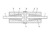
図1は本発明を適用した一実施形態の構成として接続定着具部分を示すもので、1はPCケーブル、2は接続定着具である。 FIG. 1 shows a connection fixing part as a configuration of an embodiment to which the present invention is applied. 1 is a PC cable and 2 is a connection fixing part.
図示のように、接続定着具2は、鋼製の円筒状で、一対の先細り状のスリーブ3を有し、PCケーブル1の端部を各々把持するためのクサビ4をスリーブ3にそれぞれ収納する。
そして、接続定着具2の筒状本体部分に、せん断ひずみ用の単軸ゲージによるひずみゲージ5が設けられている。
As shown in the figure, the
And the
すなわち、1本のPCケーブル1は任意の位置で切断・分離され、そのPCケーブル1の切断・分離部が接続定着具2で接続されている。
この接続定着具2の筒状本体の外周中央に、直径方向に対向して2個のひずみゲージ5が貼り付けられている。
That is, one
Two
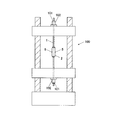
次に、図2はアムスラー試験機100を示すもので、101はウェッジ、102はスリーブである。
このアムスラー試験機100は、1,000kN等の荷重に対応したものである。
Next, FIG. 2 shows an Amsler
This Amsler
このようなアムスラー試験機100を用いて、PCケーブル1に引張力を各種付与し、その各種引張荷重に対応する接続定着具2のひずみゲージ5で検出されるひずみ値を蓄積し、試験実測データとして記録装置に記録しておく。
Using such an Amsler
そして、PC構造物施工の前施工区間の端部を含む任意の位置において、PCケーブル1に緊張力を付与した状態で、適宜の管理コンピュータを用いて、ひずみゲージ5で検出される接続定着具2の本体部分のひずみ値に基づいて、前述した各種の試験実測データが記録された記録装置から対応するPCケーブル1の緊張力として出力する。
And the connection fixing tool detected with the
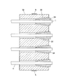
図3はPCケーブル1の引張試験装置200を示したもので、201はジャッキ、202は絞り冶具、203は絞り冶具、204はジャッキである。
この引張試験装置200は、例えば10,000kN等の大荷重に対応したものである。
FIG. 3 shows a
The
なお、図3において、2個の接続定着具2は、ダウンサイジングを図るため、図示したように、千鳥配置としている。
In FIG. 3, the two
このような大荷重に対応した引張試験装置200を用いて、接続定着具2を含むPCケーブル1に引張力を各種付与し、その各種引張荷重に対応した本体部分のひずみゲージ5のひずみ値を蓄積し、試験実測データとして記録装置に記録しておいてもよい。
Using the
以上、実施形態の接続定着具2によれば、PC構造物施工の任意の位置において、PCケーブル1に緊張力を付与した状態で、ひずみゲージ5で検出される接続定着具2のひずみ値に基づいて対応するPCケーブル1の緊張力を測定するため、PC構造物の部材寸法を極端に拡大する必要もなく、緊張端部に限らず、任意の位置において、PCケーブル1の緊張力を直接かつ容易に推定できる。
As described above, according to the
なお、図3において、接続定着具2と他のPCケーブル1との干渉を防ぐために、2個の接続定着具2の前後に3個のスペーサーリング6を配置している。
In FIG. 3, three
スペーサーリング6は、図4に示すように、直径方向に対向する一対のケーブル5本収納部61と、このケーブル5本収納部61に対し位相を90度異ならせて直径方向に対向する一対のケーブル1本収納溝62とを有している。
As shown in FIG. 4, the
図5はスペーサーリング6部分を示すもので、図示のように、ケーブル5本収納部61に5本のPCケーブル1が纏めて収納されて、ケーブル1本収納溝62に接続定着具2で接続したPCケーブル1が単独で収納されている。
FIG. 5 shows the
なお、ひずみゲージ5の引き出し線は、図6に示すように、カプラーシース11に設けたホースニップル11aから外部に導出される。
The lead wire of the
<概要2>
予めPCケーブルを挿入するシースの一部を開閉可能としておき、シース内に挿入された複数本のPCケーブルのうち一部を切断し、そのPCケーブルを接続定着具で接続し直し、その接続定着具にひずみゲージを貼り付けることで、シースの内部にカプラーを通過させることなく、当該箇所を含めたシースが極度に太くならず、PC構造物の部材寸法に影響を与えないようにすることが可能となる。
<
A part of the sheath into which the PC cable is inserted can be opened and closed in advance, a part of the plurality of PC cables inserted into the sheath is cut, the PC cable is reconnected with the connection fixing tool, and the connection fixing is performed. By attaching a strain gauge to the tool, the sheath including the part does not become extremely thick without passing the coupler inside the sheath, so that the member dimensions of the PC structure are not affected. It becomes possible.
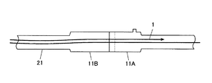
図6は図1の接続定着体2を用いるためのシース配置を示すもので、カプラーシース11は、予め中央部で前後に半割したシース分割体11A・11Bで構成されている。
FIG. 6 shows a sheath arrangement for using the
次に、図7は図6のシース21及びカプラーシース11にPCケーブル1を挿入する状態を示す工程図である。
Next, FIG. 7 is a process diagram showing a state in which the
次に、図8は図7のカプラーシース11のシース分割体11A・11Bをスライドさせて開いた状態を示す工程図である。
Next, FIG. 8 is a process diagram showing a state in which the sheath split
次に、図9は図8のPCケーブル1のうち直径方向に対向する2本のPCケーブル1を切断した状態を示す工程図である。
Next, FIG. 9 is a process diagram showing a state in which two
次に、図10は図9の切断したPCケーブル1を接続定着具2で接続した状態を示す工程図で、この接続定着具2の外周面にひずみゲージ5を貼り付けて、接続定着具2の前後において、PCケーブル1間にスペーサーリング6を配置する。
Next, FIG. 10 is a process diagram showing a state where the
次に、図11は図10のひずみゲージ5の引き出し線をホースニップル11aから外部に導出して管理コンピュータに接続した状態を示す工程図である。
Next, FIG. 11 is a process diagram showing a state in which the lead wire of the
このように、カプラーシース11のシース分割体11A・11Bを開いた開口部において、PCケーブル1を切断・分離して、そのPCケーブル1の切断・分離部を1本ずつ接続定着具2で接続し直して、その接続定着具2の筒状本体部分にひずみゲージ5を貼り付けてもよい。
In this way, the
このように、PCケーブル1のうち一部を切断・分離して、そのPCケーブル1の切断・分離部を1本ずつ接続定着具2で接続し直して、その接続定着具2の本体部分にひずみゲージ5を貼り付けておくため、シース21の内部に接続定着具2を通過させることなく、カプラーシース11を含めたシース21が極度に太くならず、PC構造物の部材寸法に影響を与えない。
In this way, a part of the
(変形例)
以上の実施形態では、複数本のPCケーブルのうち一部を切断・分離して、そのPCケーブルの切断・分離部を1本ずつ接続定着具で接続し直したが、PCケーブルの全部を切断・分離して、そのPCケーブルの切断・分離部を一括して、以下の実施形態で説明するような接続定着具で接続し直して、その接続定着具の筒状本体部分にひずみゲージを貼り付けてもよい。
(Modification)
In the above embodiment, a part of a plurality of PC cables is cut / separated, and the cutting / separating parts of the PC cables are reconnected one by one with the connection fixing tool, but the entire PC cable is cut.・ Separate and cut and separate the PC cable cutting / separating parts together with a connection fixing tool as described in the following embodiment, and attach a strain gauge to the cylindrical main body of the connection fixing tool. May be attached.
(実施形態2)
<概要>
PCケーブルの接続に用いられる接続定着具のうち、同時に緊張する複数のケーブルを纏めて接続するタイプのものを前施工区間の端部に配置し、その本体部分にひずみゲージを貼り付けて緊張を行うことで、新たな機器を取り付けることなく、またそれによりPC構造物の部材寸法を極端に拡大する必要もなく、PCケーブルの緊張力を直接かつ容易に推定できる。
(Embodiment 2)
<Overview>
Among the connection fixing tools used for connecting PC cables, the type that connects multiple cables that are simultaneously tensioned together is placed at the end of the pre-construction section, and a strain gauge is attached to the main body to apply tension. By doing so, it is possible to directly and easily estimate the tension of the PC cable without attaching new equipment and without having to extremely increase the size of the PC structure.
図12は実施形態2の接続定着具部分を示すもので、1はPCケーブル、12は接続定着具である。 FIG. 12 shows a connection fixing part of the second embodiment, wherein 1 is a PC cable and 12 is a connection fixing part.
図示のように、接続定着具12は、鋼製の円盤状で、複数対の先細り状のスリーブ13を有し、両側から複数本のPCケーブル1の端部を各々把持するためのクサビ14をスリーブ13にそれぞれ収納する。
そして、接続定着具12の本体部分にひずみゲージ5が設けられている。
As shown in the drawing, the
A
すなわち、複数本のPCケーブル1は任意の位置で切断・分離され、その複数本のPCケーブル1の切断・分離部が一括して接続定着具12で接続されている。
この接続定着具12の本体外周中央に、前述した実施形態1と同様に、直径方向に対向して2個のひずみゲージ5が貼り付けられている。
That is, the plurality of
Two
以上において、適宜の引張試験装置を用いて、接続状態のPCケーブル1及び接続定着具12に引張力を各種付与し、その各種引張荷重に対応するひずみゲージ5で検出されるひずみ値を蓄積し、試験実測データとして記録装置に記録しておく。
In the above, using an appropriate tensile test apparatus, various tensile forces are applied to the
そして、例えばPC構造物施工の前施工区間の端部において、PCケーブル1に緊張力を付与した状態で、適宜の管理コンピュータを用いて、ひずみゲージ5で検出される接続定着具12の本体部分のひずみ値に基づいて、前述した各種の試験実測データが記録された記録装置から対応するPCケーブル1の緊張力として出力する。
And, for example, at the end of the pre-construction section of the PC structure construction, the main body portion of the
(実施形態3)
図13は実施形態3の接続定着具部分を示すもので、1はPCケーブル、22は接続定着具である。
(Embodiment 3)
FIG. 13 shows a connection fixing part of the third embodiment, wherein 1 is a PC cable and 22 is a connection fixing part.
図示のように、接続定着具22は、鋼製で、両側のフランジに複数のケーブル通し孔23を有し、両側から複数本のPCケーブル1の端部をケーブル通し孔23にそれぞれ通して、そのPCケーブル1の端部に鋼製スリーブ24をそれぞれかしめ、両側のフランジにそれぞれ係着する。
As shown in the figure, the
こうして、複数本のPCケーブル1の切断・分離部を一括して接続定着具22で接続し、この接続定着具22の本体外周中央に、前述した実施形態1と同様に、直径方向に対向して2個のひずみゲージ5が貼り付けてもよい。
In this way, the cutting / separating portions of the plurality of
(実施形態4)
図14は実施形態4の端部定着具部分を示すもので、1はPCケーブル、32は端部定着具である。
(Embodiment 4)
FIG. 14 shows an end fixing unit portion according to the fourth embodiment, where 1 is a PC cable and 32 is an end fixing unit.
図示のように、端部定着具32は、鋼製の円盤状で、複数の先細り状のスリーブ33を有し、片側の一方向から複数本のPCケーブル1の端部を各々把持するためのクサビ34をスリーブ33にそれぞれ収納する。
そして、端部定着具32の本体部分にひずみゲージ5が設けられている。
As shown in the drawing, the
A
すなわち、複数本のPCケーブル1は、緊張端部において、一括して端部定着具32で固定されている。
この端部定着具32の本体外周中央に直径方向に対向して2個のひずみゲージ5が貼り付けられている。
That is, the plurality of
Two
このように、緊張端部で計測を行う場合には、一方向へPCケーブルを配置させてひずみ値を計測すればよい。 Thus, when measuring by a tension | tensile_strength part, what is necessary is just to arrange | position a PC cable to one direction and to measure a distortion value.
(他の変形例)
なお、引張試験装置としては、実施形態に限らず、各種のものを用いることができる。
(Other variations)
In addition, as a tensile test apparatus, not only embodiment but various things can be used.
1 PCケーブル
2 接続定着具
3 スリーブ
4 クサビ
5 ひずみゲージ
11 シース
12 接続定着具
13 スリーブ
14 クサビ
21 シース
22 接続定着具
23 ケーブル通し孔
24 鋼製スリーブ
32 端部定着具
33 スリーブ
34 クサビ
100 引張試験装置
200 引張試験装置
DESCRIPTION OF
Claims (4)
前記プレストレストコンクリートケーブルに緊張力を付与した状態において、前記ひずみゲージで検出される前記接続定着具本体部分のひずみ値に基づいて前記プレストレストコンクリートケーブルの緊張力を推定することを特徴とするプレストレストコンクリートケーブルの緊張力推定方法。 Cut or separate the prestressed concrete cable formed from one or multiple tensions at the same time, connect the prestressed concrete cable cutting / separation part with a connecting fixing tool, and connect it to the main part of the connecting fixing tool Affix the strain gauge,
In a state where the applied tension force to the prestressed concrete cable prestressed concrete cable, characterized in that estimating the tension of the prestressed concrete cable based on the distortion value of the connection fixing device body portion to be detected by the strain gauge Tension estimation method.
前記プレストレストコンクリートケーブルに緊張力を付与した状態において、前記ひずみゲージで検出される前記接続定着具本体部分のひずみ値に基づいて前記プレストレストコンクリートケーブルの緊張力を推定することを特徴とするプレストレストコンクリートケーブルの緊張力推定方法。 An arbitrary part of the sheath into which a plurality of prestressed concrete cables that are simultaneously tensioned can be opened and closed in advance, and a part or all of the prestressed concrete cable is cut and separated at an opening in which a part of the sheath is opened. Then, cut and separate the prestressed concrete cable one by one or all together and reconnect them with a connection fixing tool, and attach a strain gauge to the cylindrical body part of the connection fixing tool,
In a state where the applied tension force to the prestressed concrete cable prestressed concrete cable, characterized in that estimating the tension of the prestressed concrete cable based on the distortion value of the connection fixing device body portion to be detected by the strain gauge Tension estimation method.
前記プレストレストコンクリートケーブルに緊張力を付与した状態において、前記ひずみゲージで検出される前記定着具本体部分のひずみ値に基づいて前記プレストレストコンクリートケーブルの緊張力を推定することを特徴とするプレストレストコンクリートケーブルの緊張力推定方法。 Fix the end of the prestressed concrete cable formed from multiple cables that are simultaneously tensioned to the fixing tool, and attach a strain gauge to the main body of the fixing tool.
In a state where the applied tension force to the prestressed concrete cable, the prestressed concrete cable, characterized in that estimating the tension of the prestressed concrete cable based on the distortion value of the fixing device body portion to be detected by the strain gauge Tension estimation method.
Priority Applications (1)
| Application Number | Priority Date | Filing Date | Title |
|---|---|---|---|
| JP2012202768A JP5960004B2 (en) | 2012-09-14 | 2012-09-14 | Prestressed concrete cable tension estimation method |
Applications Claiming Priority (1)
| Application Number | Priority Date | Filing Date | Title |
|---|---|---|---|
| JP2012202768A JP5960004B2 (en) | 2012-09-14 | 2012-09-14 | Prestressed concrete cable tension estimation method |
Publications (2)
| Publication Number | Publication Date |
|---|---|
| JP2014059157A JP2014059157A (en) | 2014-04-03 |
| JP5960004B2 true JP5960004B2 (en) | 2016-08-02 |
Family
ID=50615768
Family Applications (1)
| Application Number | Title | Priority Date | Filing Date |
|---|---|---|---|
| JP2012202768A Active JP5960004B2 (en) | 2012-09-14 | 2012-09-14 | Prestressed concrete cable tension estimation method |
Country Status (1)
| Country | Link |
|---|---|
| JP (1) | JP5960004B2 (en) |
Families Citing this family (8)
| Publication number | Priority date | Publication date | Assignee | Title |
|---|---|---|---|---|
| JP6436716B2 (en) * | 2014-10-17 | 2018-12-12 | 株式会社エスイー | Method of connecting coupler to external cable for introducing prestress in bridge girder and tension introducing frame used in the method |
| CN108645551A (en) * | 2018-05-16 | 2018-10-12 | 广东电网有限责任公司 | Cable Pull Measuring Method |
| JP6662980B2 (en) * | 2018-10-09 | 2020-03-11 | 株式会社エスイー | Connection method of coupler to external cable for introducing prestress in bridge girder |
| CN110512520A (en) * | 2019-07-25 | 2019-11-29 | 山东大学 | An intelligent anchor for effective prestress detection under anchor and its manufacturing method |
| CN111855061B (en) * | 2020-07-29 | 2025-01-03 | 广西交科集团有限公司 | A bridge cable force increment precision measurement device and measurement method |
| CN111766009B (en) * | 2020-07-29 | 2025-01-03 | 广西交科集团有限公司 | A bridge cable force increment measurement device and measurement method |
| CN111855385A (en) * | 2020-08-11 | 2020-10-30 | 江苏亨通高压海缆有限公司 | A cable head connecting device for tension bending test of submarine cable |
| KR102341099B1 (en) * | 2021-10-21 | 2021-12-21 | 유형석 | Monitoring system for lines |
Family Cites Families (5)
| Publication number | Priority date | Publication date | Assignee | Title |
|---|---|---|---|---|
| JPS6128817Y2 (en) * | 1981-03-30 | 1986-08-26 | ||
| JPH0676927B2 (en) * | 1984-11-02 | 1994-09-28 | 大成建設株式会社 | Auxiliary member for load measurement |
| CH676617A5 (en) * | 1987-03-13 | 1991-02-15 | Dyckerhoff & Widmann Ag | |
| JPH0769136B2 (en) * | 1990-01-19 | 1995-07-26 | 応用計測工業株式会社 | Strain gauge |
| JP4102237B2 (en) * | 2003-04-01 | 2008-06-18 | 株式会社日本ピーエス | Steel wire gripping force removal device |
-
2012
- 2012-09-14 JP JP2012202768A patent/JP5960004B2/en active Active
Also Published As
| Publication number | Publication date |
|---|---|
| JP2014059157A (en) | 2014-04-03 |
Similar Documents
| Publication | Publication Date | Title |
|---|---|---|
| JP5960004B2 (en) | Prestressed concrete cable tension estimation method | |
| CN105102950B (en) | Force measuring device | |
| US9103131B2 (en) | Method and system for equally tensioning multiple strands | |
| CN103674707A (en) | System and method for measuring direct tensile strength and deformation of rock | |
| JP5206175B2 (en) | Deformation measuring device | |
| CN104895334B (en) | Prestressing force monitors intermediate plate anchorage and its anchorage anchor method in real time | |
| EP1439262A3 (en) | Rope and method for detecting damage thereof | |
| KR101552793B1 (en) | PSC Anchorage For Monitoring A Status Change of PS Steel Member and PSC Girder Using the Same | |
| CN204556394U (en) | Wire rope and rope strand axial stress fatigue measurement device | |
| Lévesque et al. | Strain measurements on ACSR conductors during fatigue tests I—Experimental method and data | |
| Claren et al. | Dynamic strain distribution on loaded stranded cables | |
| US12460699B2 (en) | Cable termination inspection cover assembly | |
| CN114791413B (en) | Nondestructive testing method for steel-cored aluminum strand crimping defects | |
| JP7294968B2 (en) | Displacement measuring device, Displacement measuring method, Tension control chart creation method | |
| JP2005134220A (en) | Axis grip sensor | |
| CN202512025U (en) | Test checking fixture for connecting rod sleeve of automobile engine | |
| CN109580201B (en) | Testing device and testing method for variable-angle cable-stayed bolt | |
| CN105397696A (en) | Shifting torque spanner | |
| Buitrago et al. | Fatigue, creep and electrical performance of subsea power cable | |
| CN111766009B (en) | A bridge cable force increment measurement device and measurement method | |
| KR20100020794A (en) | Strain bolt | |
| CN119921246A (en) | A prestressed anti-vibration hammer and a method and system for determining prestress | |
| KR101546803B1 (en) | Apparatus for Measuring Pre-Stress Loss or Strain Loss of Pre-Stressed Concrete Girder | |
| JP6373525B1 (en) | Tension fixing method for external cable type tension material | |
| KR101708825B1 (en) | Module of variable temporary retaning wall |
Legal Events
| Date | Code | Title | Description |
|---|---|---|---|
| A621 | Written request for application examination |
Free format text: JAPANESE INTERMEDIATE CODE: A621 Effective date: 20150710 |
|
| A977 | Report on retrieval |
Free format text: JAPANESE INTERMEDIATE CODE: A971007 Effective date: 20160421 |
|
| A131 | Notification of reasons for refusal |
Free format text: JAPANESE INTERMEDIATE CODE: A131 Effective date: 20160426 |
|
| A521 | Written amendment |
Free format text: JAPANESE INTERMEDIATE CODE: A523 Effective date: 20160523 |
|
| TRDD | Decision of grant or rejection written | ||
| A01 | Written decision to grant a patent or to grant a registration (utility model) |
Free format text: JAPANESE INTERMEDIATE CODE: A01 Effective date: 20160607 |
|
| A61 | First payment of annual fees (during grant procedure) |
Free format text: JAPANESE INTERMEDIATE CODE: A61 Effective date: 20160622 |
|
| R150 | Certificate of patent or registration of utility model |
Ref document number: 5960004 Country of ref document: JP Free format text: JAPANESE INTERMEDIATE CODE: R150 |