JP5966419B2 - アンテナ走査装置およびそれを用いた無線装置 - Google Patents
アンテナ走査装置およびそれを用いた無線装置 Download PDFInfo
- Publication number
- JP5966419B2 JP5966419B2 JP2012034373A JP2012034373A JP5966419B2 JP 5966419 B2 JP5966419 B2 JP 5966419B2 JP 2012034373 A JP2012034373 A JP 2012034373A JP 2012034373 A JP2012034373 A JP 2012034373A JP 5966419 B2 JP5966419 B2 JP 5966419B2
- Authority
- JP
- Japan
- Prior art keywords
- antenna
- signal
- relative phase
- phase difference
- scanning device
- Prior art date
- Legal status (The legal status is an assumption and is not a legal conclusion. Google has not performed a legal analysis and makes no representation as to the accuracy of the status listed.)
- Active
Links
Images


Classifications
-
- H—ELECTRICITY
- H01—ELECTRIC ELEMENTS
- H01Q—ANTENNAS, i.e. RADIO AERIALS
- H01Q21/00—Antenna arrays or systems
- H01Q21/0006—Particular feeding systems
- H01Q21/0031—Parallel-plate fed arrays; Lens-fed arrays
-
- H—ELECTRICITY
- H01—ELECTRIC ELEMENTS
- H01Q—ANTENNAS, i.e. RADIO AERIALS
- H01Q3/00—Arrangements for changing or varying the orientation or the shape of the directional pattern of the waves radiated from an antenna or antenna system
- H01Q3/24—Arrangements for changing or varying the orientation or the shape of the directional pattern of the waves radiated from an antenna or antenna system varying the orientation by switching energy from one active radiating element to another, e.g. for beam switching
-
- H—ELECTRICITY
- H01—ELECTRIC ELEMENTS
- H01Q—ANTENNAS, i.e. RADIO AERIALS
- H01Q3/00—Arrangements for changing or varying the orientation or the shape of the directional pattern of the waves radiated from an antenna or antenna system
- H01Q3/26—Arrangements for changing or varying the orientation or the shape of the directional pattern of the waves radiated from an antenna or antenna system varying the relative phase or relative amplitude of energisation between two or more active radiating elements; varying the distribution of energy across a radiating aperture
- H01Q3/2658—Phased-array fed focussing structure
-
- H—ELECTRICITY
- H01—ELECTRIC ELEMENTS
- H01Q—ANTENNAS, i.e. RADIO AERIALS
- H01Q3/00—Arrangements for changing or varying the orientation or the shape of the directional pattern of the waves radiated from an antenna or antenna system
- H01Q3/26—Arrangements for changing or varying the orientation or the shape of the directional pattern of the waves radiated from an antenna or antenna system varying the relative phase or relative amplitude of energisation between two or more active radiating elements; varying the distribution of energy across a radiating aperture
- H01Q3/30—Arrangements for changing or varying the orientation or the shape of the directional pattern of the waves radiated from an antenna or antenna system varying the relative phase or relative amplitude of energisation between two or more active radiating elements; varying the distribution of energy across a radiating aperture varying the relative phase between the radiating elements of an array
- H01Q3/34—Arrangements for changing or varying the orientation or the shape of the directional pattern of the waves radiated from an antenna or antenna system varying the relative phase or relative amplitude of energisation between two or more active radiating elements; varying the distribution of energy across a radiating aperture varying the relative phase between the radiating elements of an array by electrical means
- H01Q3/40—Arrangements for changing or varying the orientation or the shape of the directional pattern of the waves radiated from an antenna or antenna system varying the relative phase or relative amplitude of energisation between two or more active radiating elements; varying the distribution of energy across a radiating aperture varying the relative phase between the radiating elements of an array by electrical means with phasing matrix
-
- H—ELECTRICITY
- H01—ELECTRIC ELEMENTS
- H01Q—ANTENNAS, i.e. RADIO AERIALS
- H01Q3/00—Arrangements for changing or varying the orientation or the shape of the directional pattern of the waves radiated from an antenna or antenna system
- H01Q3/44—Arrangements for changing or varying the orientation or the shape of the directional pattern of the waves radiated from an antenna or antenna system varying the electric or magnetic characteristics of reflecting, refracting, or diffracting devices associated with the radiating element
- H01Q3/46—Active lenses or reflecting arrays
Landscapes
- Variable-Direction Aerials And Aerial Arrays (AREA)
- Aerials With Secondary Devices (AREA)
Description
本願は上記課題を解決する手段を複数含んでいるが、その一例を挙げるならば、アンテナ走査装置であって、複数のビームポートと、複数のアンテナポートとを有し、前記アンテナポートへ入出力される信号の電力分配合成を行うロトマンレンズと、前記アンテナポートに電波を入出力する複数のアンテナ要素と、それぞれの前記ビームポートに入力される信号を振幅変調する可変増幅器と、隣り合う前記ビームポートに入力される信号の相対位相差を検出する相対位相検出器と、前記相対位相検出器で検出した相対位相差に基づいて、隣り合うビームポートに供給する信号間の相対位相差を補正する位相シフタと、前記可変増幅器を経由して前記ビームポートに供給する信号の経路を選択するスイッチと、を有し、前記位相シフタは、複数の前記ビームポートに信号を供給する複数の経路のうち、1経路おきに配置されているものである。
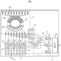
図1は、本実施例のアンテナ走査装置の構成図である。1はロトマンレンズアンテナを用いたアンテナ走査装置全体であり、2はロトマンレンズアンテナ、3は1入力多出力のスイッチ、4は可変増幅器、5は位相シフタ、6は相対位相検出器、7は走査制御部、8は伝送路、9は高周波信号端子である。ロトマンレンズアンテナ2は、ロトマンレンズ21とアンテナ要素22から構成されている。ロトマンレンズ21は、複数のビームポート24と、複数のアンテナポート23を有している。ロトマンレンズ21のアンテナポート23にはアンテナ要素22がそれぞれ接続され、各ビームポート24には振幅変調が可能な可変増幅器4の出力がそれぞれ接続されている。可変増幅器4の入力部は、位相シフタ5もしくは伝送路8が接続されており、並列に配置された可変増幅器4に対し、位相シフタ5と伝送路8を1経路おきに交互に配置する。位相シフタ5あるいは伝送路8の他方の端子には、スイッチ3が接続され、高周波信号端子9から伝播される送信信号をロトマンレンズアンテナ2へ選択的に伝播させる。
Y1=A・α1・sin(wt−θ1)
Y2=A・α2・sin(wt−θ2)
I/Qミクサに上記Y1,Y2の送信信号で混信(乗算)させると、以下の結果が得られる。
Y1・Y2=A・α1・sin(wt−θ1)×A・α2・sin(wt−θ2)
=A2・α1α2・sin(wt−θ1) sin(wt−θ2)
=A2・α1α2・1/2{−cos((wt−θ1)+(wt−θ2))+cos((wt−θ1)−(wt−θ2))}
=A2・α1α2・1/2{−cos(2wt−(θ1+θ2))− cos(θ1−θ2)}
DC成分=A2・α1α2・1/2cos(θ1−θ2)
Y1・(Y2eπ/2)=A・α1・sin(wt−θ1)×A・α2・sin(wt−θ2+π/2)
=A2・α1α2・sin(wt−θ1) sin(wt−θ2+π/2)
=A2・α1α2・1/2{−cos((wt−θ1)+(wt−θ2))+cos((wt−θ1)−(wt−θ2+π/2))}
=A2・α1α2・1/2{−cos(2wt−(θ1+θ2))− cos(θ1−θ2+π/2)}
=A2・α1α2・1/2{−cos(2wt−(θ1+θ2))+sin(θ1−θ2)}
DC成分=A2・α1α2・1/2sin(θ1−θ2)
それぞれのDC成分の比を計算すると sin(θ1−θ2)/cos(θ1−θ2)=tan(θ1−θ2) となり、相対位相差を算出することができる。相対位相検出器6で得られた相対位相量を走査制御部7に帰還し、加算器14で位相補正量に加算し、位相シフタ5の位相補正量を修正することで、隣り合う送信信号の位相差が同相となるようフィードバック制御される。
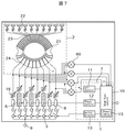
図9は、本実施例の受信用に用いるアンテナ走査装置の構成図である。1はロトマンレンズアンテナを用いたアンテナ走査装置全体であり、2はロトマンレンズアンテナ、3は1入力多出力のスイッチ、4は可変増幅器、5は位相シフタ、60は相対振幅位相検出器、7は走査制御部、8は伝送路、9は高周波信号端子である。ロトマンレンズアンテナ2は、ロトマンレンズ21とアンテナ要素22から構成されている。ロトマンレンズ21は、複数のビームポート24と、複数のアンテナポート23を有している。ロトマンレンズアンテナ2のアンテナポート23にはアンテナ要素22がそれぞれ接続され、各ビームポート24には位相シフタ5もしくは伝送路8がそれぞれ接続されている。位相シフタ5もしくは伝送路8を通過した受信信号は可変増幅器4に入力され、スイッチ3に入力される。スイッチ3にて経路選択された受信信号は電力合成され、高周波信号端子9に出力される。相対振幅位相検出器60は、アンテナ2の出力部と可変増幅器4の出力部で信号の相対度を算出する。例えば、ロトマンレンズアンテナ2の隣り合うビームポートの出力信号の位相をφ1およびφ2とし、対応する可変増幅器4の隣り合う出力信号の位相をφ1’およびφ2’とすると、前後の相対振幅位相検出器60はφ1−φ2およびφ1’−φ2’を検出する。既に説明した図1乃至図8に示された同一の符号を付された構成と、同一の機能を有する部分については説明を省略する。
2 ロトマンレンズアンテナ
3 スイッチ
4 可変増幅器
5 位相器シフタ
6 相対位相検出器
60 相対振幅位相検出器
61 入力端子
62 シングルミクサ
63 I/Qミクサ
7 走査制御部
8 伝送路
9 高周波信号端子
10 Beam Scan control
11 PA Gain Control
12 Phase Control
13 Switch Selector
14 加算器
15 Phase Table
16 可変減衰器
21 ロトマンレンズ
22 アンテナ要素
23 アンテナポート
24 ビームポート
100 送信用アンテナ走査装置
101 受信用アンテナ走査装置
102 マイクロ波帯ミリ波帯トランシーバ
103 アナログ/デジタル変換器
104 信号処理回路
105 アンテナ走査用コントローラ
106 入出力端子
107 マイクロ波帯アンテナ
110 無線装置。
Claims (15)
- 複数のビームポートと、複数のアンテナポートとを有し、前記アンテナポートへ入出力される信号の電力分配合成を行うロトマンレンズと、
前記アンテナポートに電波を入出力する複数のアンテナ要素と、
それぞれの前記ビームポートに入力される信号を振幅変調する可変増幅器と、
隣り合う前記ビームポートに入力される信号の相対位相差を検出する相対位相検出器と、
前記相対位相検出器で検出した相対位相差に基づいて、隣り合うビームポートに供給する信号間の相対位相差を補正する位相シフタと、
前記ビームポートに信号を供給する前記可変増幅器を選択するスイッチと、を有し、
前記位相シフタは、複数の前記ビームポートに信号を供給する複数の経路のうち、1経路おきに配置されていることを特徴とするアンテナ走査装置。 - 請求項1に記載のアンテナ走査装置において、
外部からのアンテナ角度情報に基づいて前記スイッチと前記可変増幅器を独立的に制御する走査制御部を備えていることを特徴とするアンテナ走査装置。 - 請求項2に記載のアンテナ走査装置において、
前記可変増幅器の振幅制御に応じて生ずる位相変動をデータ化したテーブルを前記走査制御部に記録し、当該テーブルに基づいて前記位相シフタの補正量を制御するとともに、
前記相対位相検出器で検出した隣り合うビームポートに入力される信号の相対位相差で前記補正量を修正することを特徴とするアンテナ走査装置。 - 請求項2に記載のアンテナ走査装置において、
前記可変増幅器の出力側において隣り合うビームポートに入力される信号の相対位相差を検出する相対位相検出器と、前記可変増幅器の1つおきに配置した位相シフタとを備え、
前記走査制御部は、前記相対位相検出器によって検出した相対位相差に基づいて、隣り合うビームポート間の信号相対位相差を調整する制御信号を前記位相シフタに出力することを特徴とするアンテナ走査装置。 - 請求項4に記載のアンテナ走査装置において、
前記相対位相検出器は、隣り合うビームポートに入力される信号の相対位相差に加えて、振幅差を検出するものであり、
前記走査制御部は、更に、検出した振幅差に基づいて、隣り合うビームポート間の信号相対振幅差を調整する制御信号を前記可変増幅器に出力することを特徴とするアンテナ走査装置。 - 請求項2に記載のアンテナ走査装置において、
前記可変増幅器の出力側において、前記可変増幅器の1つおきに配置した位相シフタを備え、
前記相対位相検出器は、前記位相シフタの出力側において隣り合うビームポートに入力される信号の相対位相差を検出し、
前記走査制御部は、前記相対位相検出器によって検出した相対位相差に基づいて、隣り合うビームポート間の信号相対位相差を調整する制御信号を前記位相シフタに出力することを特徴とするアンテナ走査装置。 - 請求項1に記載のアンテナ走査装置において、
前記位相シフタを配置しないビームポートに供給する信号の経路には、前記位相シフタの通過位相の変動範囲の中間の位相成分を有する伝送路を設けたことを特徴とするアンテナ走査装置。 - 請求項1に記載のアンテナ走査装置において、
ビームポートに入力される信号の相対位相差を検出する相対位相検出器はI/Qミクサから構成され、隣り合う信号を混信して得られる2つのI信号:cos(位相差)とQ信号:sin(位相差)の振幅比から2つの信号の相対位相差を検出することを特徴とするアンテナ走査装置。 - 請求項5に記載のアンテナ走査装置において、
ビームポートに入力される信号の相対位相差を検出する相対位相検出器は、1つのI/Qミクサと2つのシングルミクサから構成され、隣り合う信号をI/Qミクサで混信して得られる2つのI信号:cos(位相差)とQ信号:sin(位相差)の振幅比から2つの信号の相対位相差を検出し、シングルミクサで各々の信号振幅を算出して2つの信号振幅比を検出することを特徴とするアンテナ走査装置。 - 請求項2に記載のアンテナ走査装置において、
前記走査制御部は、ロトマンレンズアンテナのビームポートの伝播位相データを保持することにより、前記相対位相検出器で得られた信号の位相差を修正し、位相シフタの補正量を調整することを特徴とするアンテナ走査装置。 - 請求項1に記載のアンテナ走査装置において、
前記可変増幅器に代えて可変減衰器を用いたことを特徴とするアンテナ走査装置。 - 複数のビームポートと、複数のアンテナポートとを有し、前記アンテナポートへ入出力される信号の電力分配合成を行うロトマンレンズと、
前記アンテナポートに電波を入出力する複数のアンテナ要素と、
それぞれの前記ビームポートから供給される信号を振幅変調する可変増幅器と、
前記可変増幅器の前後に配置され、可変増幅器の前後での隣り合う信号の相対位相差の変動を検出する相対位相検出器と、
前記相対位相検出器で検出した相対位相差の変動に基づいて、振幅制御に伴う隣り合う信号間の相対位相差の変動を補正する位相シフタと、
前記ビームポートから信号が供給される前記可変増幅器を選択するスイッチと、を有し、
前記位相シフタは、複数の前記ビームポートから供給される信号の複数の経路のうち、1経路おきに配置されていることを特徴とするアンテナ走査装置。 - 請求項1に記載のアンテナ走査装置を用いた無線装置。
- 請求項13に記載の無線装置において、
前記アンテナ走査装置を制御するアンテナ走査コントローラと、アンテナ走査装置から入出力されるRF信号を変復調するマイクロ波帯ミリ波帯トランシーバと、該トランシーバと信号受け渡しにおいてアナログ信号とデジタル信号変換するアナログ/デジタル変換器と、デジタル化された通信信号の信号処理を行う信号処理回路と、外部デジタル機器との接続を行う入出力端子を備え、
前記信号処理回路から得られる通信品質の評価結果から、前記アンテナ走査装置のアンテナビーム走査を実施することを特徴とする無線装置。 - 請求項14に記載の無線装置において、
前記マイクロ波帯ミリ波帯トランシーバに、マイクロ波帯の送受信アンテナを設けたことを特徴とする無線装置。
Priority Applications (2)
| Application Number | Priority Date | Filing Date | Title |
|---|---|---|---|
| JP2012034373A JP5966419B2 (ja) | 2012-02-20 | 2012-02-20 | アンテナ走査装置およびそれを用いた無線装置 |
| US13/765,119 US9620865B2 (en) | 2012-02-20 | 2013-02-12 | Antenna beam scan module, and communication apparatus using the same |
Applications Claiming Priority (1)
| Application Number | Priority Date | Filing Date | Title |
|---|---|---|---|
| JP2012034373A JP5966419B2 (ja) | 2012-02-20 | 2012-02-20 | アンテナ走査装置およびそれを用いた無線装置 |
Publications (2)
| Publication Number | Publication Date |
|---|---|
| JP2013172269A JP2013172269A (ja) | 2013-09-02 |
| JP5966419B2 true JP5966419B2 (ja) | 2016-08-10 |
Family
ID=48981852
Family Applications (1)
| Application Number | Title | Priority Date | Filing Date |
|---|---|---|---|
| JP2012034373A Active JP5966419B2 (ja) | 2012-02-20 | 2012-02-20 | アンテナ走査装置およびそれを用いた無線装置 |
Country Status (2)
| Country | Link |
|---|---|
| US (1) | US9620865B2 (ja) |
| JP (1) | JP5966419B2 (ja) |
Cited By (1)
| Publication number | Priority date | Publication date | Assignee | Title |
|---|---|---|---|---|
| KR102129897B1 (ko) * | 2019-06-12 | 2020-07-03 | 조선대학교산학협력단 | 가변 빔폭을 갖는 빔틸팅 안테나 장치 |
Families Citing this family (10)
| Publication number | Priority date | Publication date | Assignee | Title |
|---|---|---|---|---|
| WO2015192361A1 (zh) * | 2014-06-19 | 2015-12-23 | 华为技术有限公司 | 一种基站及波束覆盖方法 |
| KR101752766B1 (ko) * | 2016-03-16 | 2017-07-03 | 경상대학교 산학협력단 | 송신 장치 및 송신 방법 |
| US10199742B2 (en) * | 2016-04-19 | 2019-02-05 | Raytheon Company | Passive frequency multiplexer |
| KR102242282B1 (ko) | 2017-06-26 | 2021-04-20 | 후아웨이 테크놀러지 컴퍼니 리미티드 | 전력 공급 장치 |
| US10236961B2 (en) * | 2017-07-14 | 2019-03-19 | Facebook, Inc. | Processsing of beamforming signals of a passive time-delay structure |
| US11121462B2 (en) * | 2018-02-21 | 2021-09-14 | Antenna Research Associates | Passive electronically scanned array (PESA) |
| US12199346B2 (en) * | 2020-06-18 | 2025-01-14 | Georgia Tech Research Corporation | High gain and large beamwidth rotman-lens-based and mm-wave backscattering and energy harvesting systems and associated methods |
| US11929556B2 (en) | 2020-09-08 | 2024-03-12 | Raytheon Company | Multi-beam passively-switched patch antenna array |
| EP4016127A1 (en) * | 2020-12-16 | 2022-06-22 | Provizio Limited | Multiple input multiple steered output (mimso) radar |
| CN113447894B (zh) * | 2021-06-24 | 2022-09-20 | 中国人民解放军国防科技大学 | 基于Rotman透镜的电磁拟形载荷 |
Family Cites Families (9)
| Publication number | Priority date | Publication date | Assignee | Title |
|---|---|---|---|---|
| US4042931A (en) * | 1976-05-17 | 1977-08-16 | Raytheon Company | Tracking system for multiple beam antenna |
| US4489325A (en) * | 1983-09-02 | 1984-12-18 | Bauck Jerald L | Electronically scanned space fed antenna system and method of operation thereof |
| US5936588A (en) * | 1998-06-05 | 1999-08-10 | Rao; Sudhakar K. | Reconfigurable multiple beam satellite phased array antenna |
| JP2003152422A (ja) | 2001-11-19 | 2003-05-23 | Mitsubishi Electric Corp | アレイアンテナ装置 |
| JP4523472B2 (ja) | 2005-03-31 | 2010-08-11 | Kddi株式会社 | アレーアンテナ用rf回路伝送特性調整装置およびその方法 |
| JP2007189596A (ja) * | 2006-01-16 | 2007-07-26 | Nippon Hoso Kyokai <Nhk> | ビームフォーミング装置 |
| JP4835670B2 (ja) | 2008-09-22 | 2011-12-14 | 株式会社デンソー | アンテナ装置 |
| JP4924586B2 (ja) * | 2008-10-08 | 2012-04-25 | 株式会社デンソー | アンテナ装置 |
| JP2012222523A (ja) * | 2011-04-06 | 2012-11-12 | Hitachi Chem Co Ltd | アンテナ走査装置及びそれを用いた無線通信システム |
-
2012
- 2012-02-20 JP JP2012034373A patent/JP5966419B2/ja active Active
-
2013
- 2013-02-12 US US13/765,119 patent/US9620865B2/en not_active Expired - Fee Related
Cited By (1)
| Publication number | Priority date | Publication date | Assignee | Title |
|---|---|---|---|---|
| KR102129897B1 (ko) * | 2019-06-12 | 2020-07-03 | 조선대학교산학협력단 | 가변 빔폭을 갖는 빔틸팅 안테나 장치 |
Also Published As
| Publication number | Publication date |
|---|---|
| US20130214974A1 (en) | 2013-08-22 |
| JP2013172269A (ja) | 2013-09-02 |
| US9620865B2 (en) | 2017-04-11 |
Similar Documents
| Publication | Publication Date | Title |
|---|---|---|
| JP5966419B2 (ja) | アンテナ走査装置およびそれを用いた無線装置 | |
| US11973473B2 (en) | Phased array amplifier linearization | |
| Şeker | Calibration methods for phased array radars | |
| CN108234037B (zh) | 一种相位的校准方法和电路 | |
| JP5815448B2 (ja) | フェーズドアレイ送信装置 | |
| JP2012222523A (ja) | アンテナ走査装置及びそれを用いた無線通信システム | |
| EP2911323A1 (en) | Method and apparatus for self-calibrating antenna arrays | |
| EP2993811B1 (en) | Phase adjustment device, phase difference detecting device and phase-adjusting method | |
| JP6701124B2 (ja) | レーダ装置 | |
| US9112697B2 (en) | Systems and methods of transmitter protection for wireless communications | |
| JP4245794B2 (ja) | 送信指向性補正装置及び送信指向性補正方法 | |
| JP5431374B2 (ja) | 無線通信システムおよび基地局装置 | |
| JP2013152135A (ja) | フェーズドアレーアンテナの校正経路測定装置 | |
| JP3547703B2 (ja) | 適応アレーアンテナ送受信装置 | |
| JP4850222B2 (ja) | フェーズドアレイレーダにおけるオフセット量の補正方法 | |
| JP2013005059A (ja) | 無線通信装置、送信方法、及びプログラム | |
| JP2006304205A (ja) | アンテナ位相較正装置及びそれを用いた追尾アンテナ装置 | |
| JP5694240B2 (ja) | 追尾アンテナ装置および送信位相補償方法 | |
| JP2017005647A (ja) | 位相制御装置及びアレーアンテナシステム | |
| JP2014187584A (ja) | アンテナ装置 | |
| JP2025070160A (ja) | 6ポート型測定器および測定装置 | |
| JP2017005656A (ja) | 位相異常検出装置及びアレーアンテナシステム | |
| WO2019221130A1 (ja) | アレイ通信装置、及びその制御方法 | |
| JP2006319511A (ja) | 伝送システムおよびその受信装置 | |
| JP2003133836A (ja) | アレーアンテナ装置及びアレーアンテナ信号合成方法 |
Legal Events
| Date | Code | Title | Description |
|---|---|---|---|
| A621 | Written request for application examination |
Free format text: JAPANESE INTERMEDIATE CODE: A621 Effective date: 20140709 |
|
| A977 | Report on retrieval |
Free format text: JAPANESE INTERMEDIATE CODE: A971007 Effective date: 20150612 |
|
| A131 | Notification of reasons for refusal |
Free format text: JAPANESE INTERMEDIATE CODE: A131 Effective date: 20150728 |
|
| A521 | Request for written amendment filed |
Free format text: JAPANESE INTERMEDIATE CODE: A523 Effective date: 20150924 |
|
| A131 | Notification of reasons for refusal |
Free format text: JAPANESE INTERMEDIATE CODE: A131 Effective date: 20160202 |
|
| A521 | Request for written amendment filed |
Free format text: JAPANESE INTERMEDIATE CODE: A523 Effective date: 20160401 |
|
| TRDD | Decision of grant or rejection written | ||
| A01 | Written decision to grant a patent or to grant a registration (utility model) |
Free format text: JAPANESE INTERMEDIATE CODE: A01 Effective date: 20160607 |
|
| A61 | First payment of annual fees (during grant procedure) |
Free format text: JAPANESE INTERMEDIATE CODE: A61 Effective date: 20160620 |
|
| R151 | Written notification of patent or utility model registration |
Ref document number: 5966419 Country of ref document: JP Free format text: JAPANESE INTERMEDIATE CODE: R151 |
|
| S111 | Request for change of ownership or part of ownership |
Free format text: JAPANESE INTERMEDIATE CODE: R313113 |
|
| R350 | Written notification of registration of transfer |
Free format text: JAPANESE INTERMEDIATE CODE: R350 |
|
| R250 | Receipt of annual fees |
Free format text: JAPANESE INTERMEDIATE CODE: R250 |
|
| R250 | Receipt of annual fees |
Free format text: JAPANESE INTERMEDIATE CODE: R250 |
|
| R250 | Receipt of annual fees |
Free format text: JAPANESE INTERMEDIATE CODE: R250 |
|
| R250 | Receipt of annual fees |
Free format text: JAPANESE INTERMEDIATE CODE: R250 |
|
| R250 | Receipt of annual fees |
Free format text: JAPANESE INTERMEDIATE CODE: R250 |
|
| R250 | Receipt of annual fees |
Free format text: JAPANESE INTERMEDIATE CODE: R250 |
|
| S533 | Written request for registration of change of name |
Free format text: JAPANESE INTERMEDIATE CODE: R313533 |
|
| R350 | Written notification of registration of transfer |
Free format text: JAPANESE INTERMEDIATE CODE: R350 |
|
| R250 | Receipt of annual fees |
Free format text: JAPANESE INTERMEDIATE CODE: R250 |