JP6008917B2 - Substrate detection apparatus and substrate processing apparatus - Google Patents
Substrate detection apparatus and substrate processing apparatus Download PDFInfo
- Publication number
- JP6008917B2 JP6008917B2 JP2014184103A JP2014184103A JP6008917B2 JP 6008917 B2 JP6008917 B2 JP 6008917B2 JP 2014184103 A JP2014184103 A JP 2014184103A JP 2014184103 A JP2014184103 A JP 2014184103A JP 6008917 B2 JP6008917 B2 JP 6008917B2
- Authority
- JP
- Japan
- Prior art keywords
- substrate
- swing
- detection
- initial position
- swinging
- Prior art date
- Legal status (The legal status is an assumption and is not a legal conclusion. Google has not performed a legal analysis and makes no representation as to the accuracy of the status listed.)
- Active
Links
Images


Landscapes
- Container, Conveyance, Adherence, Positioning, Of Wafer (AREA)
Description
本発明の実施形態は、基板検出装置および基板処理装置に関する。 Embodiments described herein relate generally to a substrate detection apparatus and a substrate processing apparatus.
液晶表示装置等の表示装置のガラス基板を製造する際には、この基板は、基板処理装置において搬送されながら基板には各種の処理が施される。基板処理装置が基板に施す処理としては、例えばレジスト塗布処理、レジスト剥離処理、エッチング処理、そして洗浄処理等である。例えば、基板処理装置が基板を洗浄処理する場合には、基板は基板搬送部により搬送されながら、基板の表面に洗浄処理液が供給される。 When manufacturing a glass substrate of a display device such as a liquid crystal display device, the substrate is subjected to various processes while being transported in the substrate processing apparatus. Examples of processing performed on the substrate by the substrate processing apparatus include resist coating processing, resist stripping processing, etching processing, and cleaning processing. For example, when the substrate processing apparatus cleans the substrate, the cleaning processing liquid is supplied to the surface of the substrate while the substrate is transported by the substrate transport unit.
このような基板処理装置では、基板を搬送する過程で基板の有無を検出する基板検出装置を有している。基板検出装置は、揺動可能に支持された揺動部材と、検出ローラと、マグネットと、リードスイッチを有している。検出ローラは、揺動部材の一端部において回転可能に設けられて、搬送される基板に押される。マグネットは、揺動部材の他端部に固定されている。リードスイッチは、揺動部材の揺動方向とは交差する方向に設けられている。搬送される基板が検出ローラに当たることで揺動部材が回転され、マグネットが回転方向に回転される。これにより、リードスイッチは、マグネットが発生する磁界の変化に応じて信号を出力する。このような基板の検出装置は、特許文献1に開示されている。 Such a substrate processing apparatus has a substrate detection device that detects the presence or absence of a substrate in the process of transporting the substrate. The substrate detection apparatus includes a swing member that is swingably supported, a detection roller, a magnet, and a reed switch. The detection roller is rotatably provided at one end of the swing member and is pressed by the substrate to be conveyed. The magnet is fixed to the other end of the swing member. The reed switch is provided in a direction crossing the swing direction of the swing member. When the substrate to be conveyed hits the detection roller, the swing member is rotated, and the magnet is rotated in the rotation direction. Thereby, a reed switch outputs a signal according to the change of the magnetic field which a magnet generates. Such a substrate detection apparatus is disclosed in Patent Document 1.
しかし、前述のような基板処理装置では、搬送される基板が検出ローラに当たって揺動部材が回転すると、揺動部材は振り子のように揺動運動してしまい、すぐには揺動部材の揺動運動が収束しないということがある。このため、リードスイッチは、マグネットの発生する磁界の変化を何度も検出してしまうので、基板の通過を誤検出してしまうおそれがある。また、揺動部材が収束位置へ戻るのに時間がかかるため、先の基板を検出ローラが検出して揺動部材の揺動運動が収束するまで、次の基板を搬送して検出ローラに基板を当てて検出させることができない。従って、基板搬送部が基板を搬送できる基板搬送間隔を小さくすることができず、基板の搬送効率が悪いために基板の処理効率の向上が図れない。 However, in the substrate processing apparatus as described above, when the swinging member rotates when the substrate to be conveyed hits the detection roller, the swinging member swings like a pendulum, and the swinging member swings immediately. Sometimes the motion does not converge. For this reason, since the reed switch detects the change of the magnetic field generated by the magnet many times, there is a possibility of erroneously detecting the passage of the substrate. Further, since it takes time for the swinging member to return to the convergence position, the next substrate is transported to the detection roller until the detection roller detects the previous substrate and the swinging motion of the swinging member converges. Cannot be detected. Therefore, the substrate transfer interval at which the substrate transfer unit can transfer the substrate cannot be reduced, and the substrate transfer efficiency is poor, so that the substrate processing efficiency cannot be improved.
そこで、本発明が解決しようとする課題は、揺動部材の揺動運動の収束を短くして、基板の通過の誤検出を防ぎ、しかも基板搬送間隔を小さくして基板の搬送効率を上げて基板の処理効率の向上が図れる基板検出装置および基板処理装置を提供することである。 Accordingly, the problem to be solved by the present invention is to shorten the convergence of the swinging motion of the swinging member, prevent erroneous detection of the passage of the substrate, and reduce the substrate transporting interval to increase the substrate transporting efficiency. It is an object of the present invention to provide a substrate detection apparatus and a substrate processing apparatus that can improve the processing efficiency of a substrate.
本発明の実施形態に係る基板検出装置は、基部と、前記基部に対して揺動支点部材を中心に揺動自在に取り付けられている揺動部材と、前記揺動部材の一端部に回転可能に設けられる検出ローラと、搬送される基板が前記検出ローラを押し下げて、前記基板が前記検出ローラに当たる前の前記揺動部材の初期位置から前記揺動部材が回転方向へ回転すると、前記基板を検出したことを示す検出信号を出す検出センサと、を有する基板検出装置において、前記揺動部材の前記初期位置では、前記揺動部材を前記基板の搬送方向と交差する垂直線に対して傾斜して保持する揺動ストッパを有し、この揺動ストッパは、前記揺動部材を、前記初期位置において、前記垂直線に対して30度から50度の範囲の傾斜角度で保持し、前記揺動部材は、他端部にウエイトが設けられ、前記検出ローラの取り付け軸部と前記揺動支点部材との間の距離が、前記揺動支点部材と前記ウエイト間の距離にくらべて、短いことを特徴とする。また、本発明の実施形態に係る基板検出装置は、 基部と、前記基部に対して揺動支点部材を中心に揺動自在に取り付けられている揺動部材と、前記揺動部材の一端部に回転可能に設けられる検出ローラと、搬送される基板が前記検出ローラを押し下げて、前記基板が前記検出ローラに当たる前の前記揺動部材の初期位置から前記揺動部材が回転方向へ回転すると、前記基板を検出したことを示す検出信号を出す検出センサと、を有する基板検出装置において、前記揺動部材の前記初期位置では、前記揺動部材を前記基板の搬送方向と交差する垂直線に対して傾斜して保持する揺動ストッパを有し、この揺動ストッパは、前記揺動部材を、前記初期位置において、前記垂直線に対して30度から50度の範囲の傾斜角度で保持し、前記揺動部材の前記初期位置における傾斜方向は、前記揺動部材の前記一端部が前記基板の搬送方向上流側に傾斜する方向であることを特徴とする。 A substrate detection apparatus according to an embodiment of the present invention includes a base, a swinging member attached to the base so as to be swingable about a swinging fulcrum member, and rotatable at one end of the swinging member. When the swinging member rotates in the rotation direction from the initial position of the swinging member before the substrate hits the detection roller, the detection roller provided on the substrate and the substrate to be conveyed push down the detection roller. And a detection sensor that outputs a detection signal indicating that the detection has been performed, wherein the swing member is tilted with respect to a vertical line that intersects the transport direction of the substrate at the initial position of the swing member. has a rocking stopper holding Te, the swing stopper said rocking member in said initial position, and held at a tilt angle ranging from 30 degrees to 50 degrees from the vertical line, the swing Other members Part weights provided, the distance between the mounting shaft portion and the rocking support member of the detection roller, the compared to the distance between the rocking support member and the weight, and wherein the shorter. Further, the substrate detection apparatus according to the embodiment of the present invention includes a base, a swinging member attached to the base so as to be swingable about a swinging fulcrum member, and one end of the swinging member. When the swinging member rotates in the rotation direction from the initial position of the swinging member before the substrate hits the detection roller, the detection roller provided rotatably and the substrate to be conveyed pushes down the detection roller, And a detection sensor that outputs a detection signal indicating that the substrate has been detected, and at the initial position of the swing member, the swing member is moved with respect to a vertical line that intersects the transport direction of the substrate. The swing stopper has a swing stopper that is tilted and holds the swing member at a tilt angle in a range of 30 to 50 degrees with respect to the vertical line at the initial position. Swing member The inclination direction at the initial position is a direction in which the one end portion of the swinging member is inclined toward the upstream side in the transport direction of the substrate.
本発明によれば、揺動部材の揺動運動の収束を短くして、基板の通過の誤検出を防ぎ、しかも基板搬送間隔を小さくして基板の搬送効率を上げて基板の処理効率の向上が図れる基板検出装置および基板処理装置を提供することができる。 According to the present invention, the convergence of the swinging motion of the swinging member is shortened to prevent erroneous detection of the passage of the substrate, and the substrate transporting interval is shortened to increase the substrate transporting efficiency to improve the substrate processing efficiency. It is possible to provide a substrate detection apparatus and a substrate processing apparatus capable of achieving the above.
本発明の実施形態について、図面を参照して説明する。
(第1実施形態)
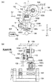
図1は、本発明の基板処理装置の好ましい第1実施形態を示す図である。図2は、図1に示す基板処理装置に設けられている基板検出装置2の構造例と動作例を示す図である。
Embodiments of the present invention will be described with reference to the drawings.
(First embodiment)
FIG. 1 is a view showing a first preferred embodiment of the substrate processing apparatus of the present invention. FIG. 2 is a diagram showing a structural example and an operation example of the
図1に示すように、本発明の実施形態は、一例として、処理対象基板である。例えば、液晶表示装置用のガラス基板B(以下、基板という)を搬送方向Tに沿って搬送しながら、この基板Bの表裏面に洗浄処理液を供給することにより、基板Bの表面上の汚れを洗浄処理する。この洗浄処理液としては、例えば純水を用いるが、これに限定されない。 As shown in FIG. 1, the embodiment of the present invention is a substrate to be processed as an example. For example, when a glass substrate B for a liquid crystal display device (hereinafter referred to as a substrate) is transported along the transport direction T and a cleaning treatment liquid is supplied to the front and back surfaces of the substrate B, dirt on the surface of the substrate B is obtained. Wash. As this cleaning treatment liquid, for example, pure water is used, but is not limited thereto.
図1に例示する基板処理装置1は、基板検出装置2を備えており、基板検出装置2は基板有無検出装置ともいう。この基板検出装置2は、例えば複数の搬送ローラ3の内の隣接する2つの搬送ローラ3の間に設けられている。各搬送ローラ3は、搬送シャフト3Aに取り付けられている。搬送シャフト3Aは、図示しない駆動部のモータを駆動することで回転可能である。この搬送シャフト3Aは、X方向(図1の紙面垂直方向)に沿って配置されている。図1と図2に示すように、基板検出装置2は、基部4と、揺動部材5と、検出ローラ6と、マグネット7と、検出センサ8(例えば、リードスイッチ)と、揺動支点部材10と、揺動ストッパ11を有している。
A substrate processing apparatus 1 illustrated in FIG. 1 includes a
図1と図2に示す基部4は、金属板を折り曲げて形成した部材であり、Z方向(上下方向)に沿って形成されている取付け部9を有している。この取付け部9には、揺動部材5が、揺動支点部材10を中心にして揺動可能に取付けられている。揺動部材5は、金属製の板状の部材である。Z方向は、基板Bの搬送方向TとX方向に対して直交垂直方向である。揺動部材5は、揺動支点部材10を中心にして、取付け部9に沿って、Z方向と搬送方向Tで形成される面内において、回転方向Rと逆回転方向R1に沿って揺動可能である。
The
図1と図2に示す検出ローラ6は、例えば樹脂製であり、取り付け軸部12を用いて揺動部材5の一端部5Aに、回転可能に取り付けられている。揺動部材5の他端部5Bは、金属製のウエイト5Cを固定している。ウエイト5Cは、検出ローラ6との重量バランスを取るために設けられている。マグネット7は、好ましくはウエイト5Cの中に取り付けられている。
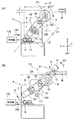
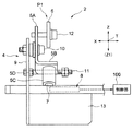
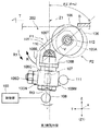
図2(A)は、揺動部材5が初期位置P1に位置決めされている状態を示し、図2(B)は、揺動部材5が回転方向Rに回転して検出位置P2に位置決めされている状態を示している。図3は、図2(A)に示すCR方向から見た基板検出装置2の側面図である。
2A shows a state where the
図2(A)と図3に示すように、揺動ストッパ11は、取付け部9において、X方向に沿って突出するようにして、揺動部材5の他端部5B寄りの位置に固定されている。この揺動ストッパ11は、揺動部材5の他端部5B寄りの下側側面部5Dを直接突き当てることで、揺動部材5を図1と図2(A)に示す初期位置P1において、角度θで傾斜した状態で位置決めさせる機能を有している。揺動部材5の一端部5Aから他端部5Bに至るまでの部分は、直線状の板部材であるが、図3に示すように他端部5Bは、90度折り曲げることでX方向に突出している。
As shown in FIGS. 2A and 3, the
図1と図2(A)に示すように、検出センサ8は、揺動部材5が図2(A)に示す初期位置P1に位置されている状態で、マグネット7にわずかな間隔を離した状態で対面するように、基部4の取付け部13に固定されている。検出センサ8は、揺動部材5が回転方向Rに回転して、図2(A)に示す初期位置P1から図2(B)に示す検出位置P2になった時に、すなわち基板Bが検出ローラ6を押し下げた時に、マグネット7の発生する磁界の変化を検出する。これにより、検出センサ8は、基板Bの検出信号DSを、基板Bを検出した信号として制御部100に送る。
As shown in FIG. 1 and FIG. 2 (A), the
図2(A)では、揺動部材5が初期位置P1に位置決めされていることで、揺動部材5の長手方向Gは、Z方向の垂直線Z1に対して角度θで傾斜している。この状態では、揺動部材5の長手方向Gは、検出ローラ6の取り付け軸部12の中心と、揺動支点部材10の中心と、マグネット7の中心と、検出センサ8の中心を通っている。検出ローラ6の取り付け軸部12と揺動支点部材10との間の距離L1は、揺動支点部材10とマグネット7(ウエイト5C)との間の距離L2に比べて、好ましくは短く設定されている。これにより、揺動部材5が図2(B)に示す検出位置P2から初期位置P1に逆回転方向R1に回転して復帰することができる。
In FIG. 2A, since the
図2に示すように、初期位置P1では、この揺動部材5の長手方向Gは、Z方向の垂直線Z1に対して、所定の角度θだけ揺動支点部材10を中心にして傾けてある。マグネット7は、検出センサ8に対面している。揺動ストッパ11には、揺動部材5の下側側面部5Dが当接している。この角度θは、例えば40度である。角度θの範囲は、好ましくは30度から50度の範囲である。角度θが30度未満であると、検出ローラ6が基板Bにより回転方向Rに押し下げられた場合に、検出ローラ6が回転方向Rに回転してしまう角度が大きくなり、揺動部材5が検出位置P2から初期位置P1に復帰するまでの復帰時間が長くかかるので、好ましくない。また、角度θが50度を超えると、検出ローラ6が基板Bにより回転方向Rに押し下げられた場合に、検出ローラ6が回転方向Rに回転する角度は小さいが、マグネット7が検出センサ8から遠ざかる距離が小さい(マグネットの逃げ距離が小さい)ので、検出センサ8はマグネット7の磁界の変化を検出し難いことから、好ましくない。
As shown in FIG. 2, at the initial position P1, the longitudinal direction G of the
これに対して、図2(B)に示すように、揺動部材5が検出位置P2に回転した時に、すなわち基板Bが検出ローラ6を押し下げた時には、揺動部材5の長手方向Gは、Z方向の垂直線Z1に対して、所定の角度θに加えて追加の回転角度θ1だけ、揺動支点部材10を中心にしてさらに回転方向Rに回転される。これにより、マグネット7は、検出センサ8から回転方向Rに離れる。揺動ストッパ11は、揺動部材5の下側側面部5Dから離れる。この回転角度θ1の例としては、15.5度であるが、特に限定されない。
On the other hand, as shown in FIG. 2B, when the
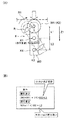
図4は、揺動部材Kの重量バランスについて示している。図4(A)に示す重量W1は、揺動部材Kの揺動支点(振子支点)K1から上の部分であって、検出ローラK2までの重量を示し、重量W2は、揺動部材Kの揺動支点K1から下の部分であって、マグネットK3とウエイトK4までの重量を示している。距離L1は、揺動支点K1から検出ローラK2の回転中心までの距離であり、距離L2は、揺動支点K1からマグネットK3までの距離である。 FIG. 4 shows the weight balance of the swing member K. A weight W1 shown in FIG. 4A is a portion above the swinging fulcrum (pendulum fulcrum) K1 of the swinging member K and indicates the weight to the detection roller K2. The weight W2 is the weight of the swinging member K. The part below the swing fulcrum K1 and the weight from the magnet K3 to the weight K4 is shown. The distance L1 is a distance from the swing fulcrum K1 to the rotation center of the detection roller K2, and the distance L2 is a distance from the swing fulcrum K1 to the magnet K3.
図4(B)に示す反力W0は、検出ローラK2が基板を検出する際に、検出ローラK2が基板から受ける突き上げ反力である。図4(B)において、揺動部材Kの揺動支点K1を中心とする倒れ易さ(回転し易さ)は、(W0+W1)×L1>W2×L2で表すことができ、W2×L2の値が小さい程、揺動部材Kの重量バランスは安定する。また、揺動部材Kの逆回転方向R1への戻り易さ(復帰し易さ)は、W1×L1<W2×L2で表すことができ、W2×L2の値が大きい程、揺動部材Kは逆回転方向R1へ戻り易くなる。 The reaction force W0 shown in FIG. 4B is a thrust reaction force that the detection roller K2 receives from the substrate when the detection roller K2 detects the substrate. In FIG. 4B, the ease of falling (easy to rotate) about the swing fulcrum K1 of the swing member K can be expressed by (W0 + W1) × L1> W2 × L2, and W2 × L2 The smaller the value is, the more stable the weight balance of the swing member K is. Further, the ease of return of the swing member K in the reverse rotation direction R1 (the ease of return) can be expressed by W1 × L1 <W2 × L2, and the larger the value of W2 × L2, the swing member K becomes. Becomes easy to return to the reverse rotation direction R1.
図5(A)は、半径の小さい検出ローラK2Aに対して基板Bが突き当たった状態を示し、図5(B)は、図5(A)の検出ローラK2Aに比べて、半径の大きい検出ローラK2Bに対して基板Bが突き当たった状態を示している。 FIG. 5A shows a state in which the substrate B has abutted against a detection roller K2A having a small radius, and FIG. 5B shows a detection roller having a larger radius than the detection roller K2A in FIG. 5A. A state in which the substrate B abuts against K2B is shown.
半径の小さい検出ローラK2Aと、この検出ローラK2Aに比較して半径の大きい検出ローラK2Bが、それぞれ基板BによりZ1方向に押し下げられる量SS(例えば3mm)を同じであるとすると、図5(B)に示す検出ローラK2Bの基板入射角C2は、図5(A)に示す検出ローラK2Aの基板入射角C1に比べて小さくすることができる。この基板入射角とは、検出ローラが基板BによりZ1方向に押し下げられた時に検出ローラ自体が垂直軸Z1に沿って押し下げられる角度である。これにより、半径の大きい検出ローラK2Bを用いる方が、半径の小さい検出ローラK2Aを用いるのに比べて、検出ローラが回転方向Rに回転した時に垂直線Z1方向に逃げ易い。言い換えれば、揺動部材が回転方向R側に倒れ易いことになる。検出ローラの好ましい直径は、例えば20mmであるが、特に限定されない。 Assuming that the detection roller K2A having a small radius and the detection roller K2B having a larger radius than the detection roller K2A have the same amount SS (for example, 3 mm) pushed down in the Z1 direction by the substrate B, FIG. The substrate incident angle C2 of the detection roller K2B shown in FIG. 5 can be made smaller than the substrate incident angle C1 of the detection roller K2A shown in FIG. The substrate incident angle is an angle at which the detection roller itself is pushed down along the vertical axis Z1 when the detection roller is pushed down in the Z1 direction by the substrate B. Accordingly, when the detection roller K2B having a large radius is used, it is easier to escape in the direction of the vertical line Z1 when the detection roller rotates in the rotation direction R than when the detection roller K2A having a small radius is used. In other words, the swing member is likely to fall down in the rotation direction R side. A preferable diameter of the detection roller is, for example, 20 mm, but is not particularly limited.
次に、上述した本発明の実施形態の動作例を説明する。 Next, an operation example of the above-described embodiment of the present invention will be described.
図1に示す基板処理装置1では、図示しない駆動源のモータが動作すると、搬送シャフト3Aが回転することで、搬送ローラ3は基板Bを順次搬送方向Tに沿って搬送する。この基板処理装置1は、例えば、基板洗浄装置であって、基板Bに対して純水のような洗浄処理液が供給されることで、基板Bは洗浄処理され、基板B上の洗浄処理液が高圧エアにより吹き飛ばされて乾燥される。
In the substrate processing apparatus 1 shown in FIG. 1, when a motor of a drive source (not shown) operates, the
図1に示すように、基板Bが搬送方向Tに搬送される途中で、基板Bが基板検出装置2の上を通過すると、図2(A)に示す検出ローラ6は基板Bの裏面により押されるので、図2(A)に示す揺動部材5が初期位置P1に位置されている状態から、図2(B)に示す検出位置P2に回転する。
As shown in FIG. 1, when the substrate B passes over the
基板Bが通過して基板Bが検出ローラ6を押し下げた時には、揺動部材5の長手方向Gは、Z方向の垂直線Z1に対して、予め設定されている所定の角度θに加えて回転角度θ1だけ、揺動支点部材10を中心にして回転方向Rにさらに回転される。これにより、マグネット7は、検出センサ8から回転方向Rに離れる。揺動部材5の下側側面部5Dは、揺動ストッパ11から離れる。これにより、マグネット7は、図2(A)に示す検出センサ8に対向した状態から図2(B)に示す離れることにより、磁界を生じなくなる。検出センサ8がこの磁界が生じなくなったことを示す検出信号DSを制御部100に送って制御部100が認識することで、制御部100は基板Bを検出していると判断する。
When the substrate B passes and the substrate B pushes down the
逆に、基板Bがさらに搬送方向Tに搬送されて、基板Bが検出ローラ6から離れると、揺動部材5は重力の力で逆回転方向R1に回転して検出位置P2から初期位置P1に復帰するので、マグネット7が検出センサ8から離れた状態から対向した状態に戻ると磁界を発生したことを検出センサ8が検出するので、制御部100は磁界が発生したことを認識して、基板Bは検出していないと判断する。
On the contrary, when the substrate B is further transported in the transport direction T and the substrate B is separated from the
このように、基板Bが検出ローラ6から離れると、揺動部材5が重力の力で検出位置P2から初期位置P1に逆回転方向R1に回転するので、レスポンス良く直ちに初期位置P1に復帰できる。しかも、揺動部材5の下側側面部5Dは、揺動ストッパ11に当接する。
Thus, when the substrate B is separated from the
これにより、揺動部材5は回転方向Rと逆回転方向R1について振り子のように揺れ動く動作(チャタリング)を全く起こすことなく、揺動部材5は初期位置P1に直ちに位置決めすることができる。基板Bが検出ローラ6から離れると、揺動部材5が検出位置P2から初期位置P1に逆回転方向R1に回転して直ちに復帰できるのは、すでに説明したように、揺動部材5が初期位置P1において、回転方向R側に向けて予め角度θだけ傾斜して保持されているからである。しかも、図2(A)に示すように、好ましくは検出ローラ6の取り付け軸部12と揺動支点部材10との間の距離L1が、揺動支点部材10とマグネット7(ウエイト5C)との間の距離L2に比べて、好ましくは短く設定されているからである。
As a result, the swinging
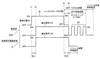
ここで、図6を参照する。図6は、図2の基板Bの動きに伴い、本発明の実施形態における検出センサ8が出力する検出信号と、従来例の基板検出装置502における検出センサが出力する検出信号を比較して示す図である。
Reference is now made to FIG. FIG. 6 shows a comparison between the detection signal output from the
本発明の実施形態における基板検出装置2では、図2(A)と図2(B)に示すように、基板Bが通過して図6の時点t1において、検出ローラ6を垂直線Z1方向に押し下げると、揺動部材5が初期位置P1に位置決めされている状態から回転方向Rに回転して、時点t3において検出位置P2に位置決めされる。これにより、マグネット7は、図2(A)に示す検出センサ8に最接近した状態から図2(B)に示す離れた状態になるので、図6の時点t1から時間DL1だけわずかに遅れた時点t3において、検出センサ8は制御部100に検出信号DSを発生する。図6に示すように、基板Bが搬送されて基板Bが検出ローラ6を押し下げている間は、検出信号DSを発生している。そして、図6の時点t2で基板Bが通過すると、揺動部材5が検出位置P2から初期位置P1に復帰するので、マグネット7は、検出センサ8から離れた状態から接近した状態に戻ることから、時点t2から時間DL2だけわずかに遅れた時点t4において、検出信号DSの発生は終わる。時点t4の後には、ソフトウェア上必要な時間余裕を設定する。
In the
これに対して、図6に示す従来の基板検出装置502では、図6の時点t1から時間DL1だけわずかに遅れた時点t3において、検出センサは検出信号ESを発生する。そして、図6の時点t2で基板Bが通過してしまうと、時点t2から時間DL2だけわずかに遅れた時点t4において、検出信号ESの発生は終わる。しかし、時点t4以降においては、例えば2秒間から3秒間、検出センサからはチャタリング波形EFが発生してしまう。このように、時点t4以降において、チャタリング波形EFが発生してしまうのは、揺動部材自体が振り子のように揺動運動してしまい、揺動部材が収束位置(中立位置)へ戻るための収束時間がかかってしまうためである。
On the other hand, in the conventional
本発明の実施形態の基板検出装置2では、図1と図2に示すように、揺動部材5は初期状態P1において回転方向R側に向けて予め傾斜して保持されている。しかも図2(A)から図2(B)に示すように、揺動部材5が初期位置P1から検出位置P2に変化した後、基板Bが通り過ぎて検出ローラ6が基板Bにより押し下げられなくなると、図2(A)に示すように揺動部材5は、検出状態P2から初期状態P1へ逆回転方向R1に回転して即座に初期位置P1に復帰できる。このように、揺動部材5が検出状態P2から初期状態P1に即座に復帰すると、揺動ストッパ11には、揺動部材5の他端部5B寄りの下側側面部5Dが直接突き当たる。このため、揺動部材5は、図1と図2(A)に示す初期位置P1に迅速にしかも確実に位置決めさせることができる。従来生じていたチャタリング波形EFが発生することはなく、揺動部材5の揺動運動の収束を短くして、基板Bの通過の誤検出を防げる。しかも、揺動部材5の揺動運動の収束を短くできるので、順次搬送される複数の基板B同士の搬送間隔を小さくしても、基板Bの有無の検出を確実に行えるので、基板Bを搬送しながらの基板処理効率を上げることができる。
In the
(第2実施形態)
次に、本発明の基板処理装置の好ましい第2実施形態を説明する。
図7(A)は、本発明の第2実施形態の基板処理装置が備える基板検出装置102を示す正面図であり、図7(B)は、図7(A)に示す基板処理装置102を矢印HJから見た側面図である。
(Second Embodiment)
Next, a second preferred embodiment of the substrate processing apparatus of the present invention will be described.
FIG. 7A is a front view showing the
基板検出装置102は基板有無検出装置ともいう。この基板検出装置102は、例えば図1に示す基板処理装置1の複数の搬送ローラ3の内の隣接する2つの搬送ローラ3の間に設けられている。図7(A)と図7(B)に示すように、基板検出装置102は、基部104と、揺動部材105と、ウエイト105Cと、追加ウエイト105Dと、検出ローラ106と、マグネット107と、リードスイッチのような検出センサ108と、揺動支点部材110と、揺動ストッパ111を有している。
The
取り付け部109には、揺動部材105が、揺動支点部材110を中心にして揺動可能に取り付けられている。揺動部材105は、金属製の板状の部材である。揺動部材105は、図7(A)に示す初期位置P1に位置決めされている状態では、Z方向の垂直線Z1に沿って形成されている第1部分105Sと、傾斜線Vに沿って形成されている第2部分105Tを有している。傾斜線Vは、垂直線Z1とは所定の角度θだけ、回転方向R側に傾斜している。この角度θの値は、好ましくは第1実施形態における角度θの値と同じである。Z方向は、基板Bの搬送方向TとX方向に対して直交している。揺動部材105は、揺動支点部材110を中心にして、取付け部109の面に沿って、Z方向と搬送方向Tで形成される面内において、回転方向Rに沿って揺動可能である。
A
図7(A)と図7(B)に示す検出ローラ106は、例えば樹脂製であり、取り付け軸部112を用いて揺動部材105の一端部105Aにおいて、回転可能に取り付けられている。揺動部材105の他端部105Bは、金属製のウエイト105Cを固定しており、このウエイト105Cには、マグネット107が設けられている。ウエイト105Cは、検出ローラ106との重量バランスを取るために設けられている。マグネット107は、好ましくはウエイト105Cの中に取り付けられている。
The
図7(A)に示すように、ウエイト105Cには、さらに追加ウエイト105Dが追加して設けられている。しかも、ウエイト105Cは、揺動ストッパ111に突き当てる突き当て面105Mを有し、追加ウエイト105Dは、この突き当て面105Mとは反対側になるウエイト105Cの面105Nに固定されている。これにより、追加ウエイト105Dの荷重は、ウエイト105Cによる荷重に加えて、検出ローラ106と逆方向(逆回転方向R1)へ追加荷重を与えるので、揺動部材105には回転方向Rとは逆の逆回転方向R1へ揺動ベクトルを発揮でき、すなわち揺動ストッパ111へ突き当てる方向へ揺動ベクトルを発揮する。
As shown in FIG. 7A, the
図7(A)では、揺動部材105が実線で示す初期位置P1に位置決めされている状態と、揺動部材105が回転方向Rに回転して、破線で示す検出位置P2に位置決めされている状態の両方を示している。揺動ストッパ111は、ウエイト105Cに直接突き当たることで、揺動部材5を図7(A)の実線で示す初期位置P1に位置決めさせる機能を有している。図7(A)と図7(B)に示すように、検出センサ108は、揺動部材105が図7(A)に示す初期位置P1に位置されている状態で、マグネット107に対面するように、図7(B)に示す基部104に固定されている。検出センサ108は、揺動部材105が実線で示す初期位置P1から破線で示す検出位置P2に回転した時に、すなわち基板Bが検出ローラ106を押し下げた時に、マグネット107の発生する磁界の変化を検出する。これにより、検出センサ108は、基板Bの検出信号DSを、制御部100に送る機能を有する。
In FIG. 7A, the
次に、上述した本発明の第2実施形態の基板処理装置1の基板検出装置102の動作例を説明する。
Next, an operation example of the
図7(A)に示す基板Bが搬送方向Tに沿って搬送されると、この基板処理装置が例えば基板洗浄装置であって、基板Bに対して純水のような洗浄処理液が供給されることで、基板Bは洗浄処理され、基板B上の洗浄処理液が高圧エアにより吹き飛ばされることで乾燥される。 When the substrate B shown in FIG. 7A is transported along the transport direction T, this substrate processing apparatus is, for example, a substrate cleaning apparatus, and a cleaning processing liquid such as pure water is supplied to the substrate B. Thus, the substrate B is cleaned and dried by blowing the cleaning solution on the substrate B with high-pressure air.
基板Bが搬送方向Tに搬送される途中で、基板Bが基板検出装置102の上を通過すると、図7(A)に示す検出ローラ106は基板Bの下面に押されるので、図7(A)に示す揺動部材105が初期位置P1に位置されている状態から検出位置P2に回転方向Rに沿って回転する。これにより、マグネット107は、検出センサ108から回転方向Rに離れる。揺動ストッパ111は、ウエイト105Cから離れる。これにより、マグネット107は、検出センサ108が最接近した状態から離れた状態になるので、検出センサ108は制御部100に検出信号DSを発生する。
If the substrate B passes over the
そして、基板Bがさらに搬送方向Tに搬送されて、基板Bが検出ローラ106から離れると、揺動部材105が検出位置P2から初期位置P1に逆回転方向R1に回転して復帰するので、マグネット107は、検出センサ108から離れた状態から最接近した状態に戻ることから、検出センサ108からの検出信号DSの発生は終わる。
Then, when the substrate B is further transported in the transport direction T and the substrate B is separated from the
このように、基板Bが検出ローラ106から離れると、揺動部材105は、検出位置P2から初期位置P1に逆回転方向R1に回転して直ちに初期位置P1に復帰できる。しかも、揺動部材5のウエイト105Cが、揺動ストッパ111に突き当たる。これにより、揺動部材105は振り子のようなチャタリング動作を起こすことなく、初期位置P1に直ちに位置決めすることができる。
As described above, when the substrate B is separated from the
基板Bが検出ローラ106から離れると、揺動部材105が検出位置P2から初期位置P1に逆回転方向R1に回転して直ちに復帰できるのは、すでに説明したように、揺動部材5の第2部分105Tが第1部分105Sに対して回転方向R側に予め角度θだけ傾斜しているからである。しかも、追加ウエイト105Dは、検出ローラ106と逆方向へ荷重を与えることにより、揺動部材105には回転方向Rとは逆方向の逆回転方向R1へ揺動して、揺動ストッパ111に対して当接する。このため、図7に示す基板検出装置102は、揺動部材105の揺動運動の収束を短くして、基板Bの通過の誤検出を防げる。しかも、揺動部材105の揺動運動の収束を短くできるので、順次搬送される複数の基板B同士の搬送間隔を小さくしても、基板Bの有無の検出を確実に行えるので、基板を搬送しながらの基板処理効率を上げることができる。
When the substrate B is separated from the
(第3実施形態)
次に、本発明の基板処理装置の好ましい第3実施形態を説明する。
図8は、本発明の第3実施形態の基板処理装置が備える基板検出装置202を示す正面図である。図8に示す基板検出装置202の構造は、図7(A)と図7(B)に示す基板検出装置102の構造とほぼ同じであるが、次の点が異なる。
(Third embodiment)
Next, a third preferred embodiment of the substrate processing apparatus of the present invention will be described.
FIG. 8 is a front view showing the
図8に示すように、基部(図示せず)と、揺動部材105と、ウエイト105Cと、追加ウエイト105Dと、検出ローラ106と、マグネット107と、リードスイッチのような検出センサ108と、揺動支点部材110と、揺動ストッパ111を有している。揺動部材105は、図7(A)に示す初期位置P1に位置決めされている状態では、Z方向の垂直線Z1に沿って形成された第1部分105Sと、傾斜線Vに沿って形成された第2部分105Tを有している。傾斜線Vは、垂直線Z1とは所定の角度θ2だけ傾斜している。
As shown in FIG. 8, a base (not shown), a
この傾斜角度θ2は、角度θと角度uを足した角度である。この基板検出装置202の基部(図示せず)と、揺動部材105と、ウエイト105Cと、追加ウエイト105Dと、検出ローラ106と、マグネット107と、リードスイッチのような検出センサ108と、揺動支点部材110と、揺動ストッパ111は、図7に示す基板検出装置102の基部104と、揺動部材105と、ウエイト105Cと、追加ウエイト105Dと、検出ローラ106と、マグネット107と、リードスイッチのような検出センサ108と、揺動支点部材110と、揺動ストッパ111と同じものである。
The inclination angle θ2 is an angle obtained by adding the angle θ and the angle u. A base (not shown) of the
ただし、揺動部材105の第1部分105Sの長手方向RGは、Z方向の垂直線Z1に対して、予め角度uだけ傾斜されている。つまり、揺動ストッパ111が、垂直線Z1側に寄せて固定されており、揺動部材105は角度uだけ傾斜した状態で、ウエイト105Cが揺動ストッパ111に対して突き当たっていることで、揺動部材105は初期位置P1に位置決めされている。
However, the longitudinal direction RG of the
基板Bが検出ローラ106を押し下げた時には、揺動部材105が、揺動支点部材110を中心にして回転方向Rに回転される。これにより、マグネット107は、検出センサ108から回転方向Rに離れる。揺動ストッパ111は、ウエイト105Cから離れる。これにより、マグネット107は、検出センサ108に対向した状態から離れた状態になるので、検出センサ108は制御部100に検出信号DSを発生する。
When the substrate B pushes down the
そして、基板Bがさらに搬送方向Tに搬送されて、基板Bが検出ローラ106から離れると、揺動部材105が検出位置P2から初期位置P1に逆回転方向R1に回転して初期位置P1に復帰するので、マグネット107は、検出センサ108から離れた状態から接近した状態に戻るので、検出センサ108からの検出信号DSの発生は終わる。
When the substrate B is further transported in the transport direction T and the substrate B is separated from the
このように、基板Bが検出ローラ106から離れると、揺動部材105が検出位置P2から初期位置P1に逆回転方向R1に回転して直ちに初期位置P1に復帰し、しかも揺動部材5のウエイト105Cは、揺動ストッパ111に突き当たるので、揺動部材105は振り子のように揺れ動く動作(チャタリング)を起こすことなく、揺動部材105は初期位置P1に直ちに位置決めすることができる。
Thus, when the substrate B moves away from the
図8に示す揺動部材105は、図7の揺動部材105に比べて、初期位置P1においても予めさらにオフセット角度uだけ回転方向R側に傾けている。しかも、追加ウエイト105Dは、検出ローラ106とは逆方向へ荷重を与えることにより、揺動部材105には逆回転方向R1へ揺動ベクトルを発揮でき、すなわち揺動ストッパ111へ当接する方向へ揺動ベクトルを発揮できるからである。これにより、図8に示す基板検出装置202は、図7に示す基板検出装置102に比べて、基板検出動作における回転方向Rへの回転および逆回転方向R1への復帰を、さらに高めることができる。このため、図8に示す基板検出装置202は、揺動部材105の揺動運動の収束を短くして、基板Bの通過の誤検出を防げる。しかも、揺動部材105の揺動運動の収束を短くできるので、順次搬送される複数の基板B同士の搬送間隔を小さくしても、基板Bの有無の検出を確実に行えるので、基板を搬送しながらの基板処理効率を上げることができる。
The
本発明の実施形態に係る基板処理装置は、搬送される基板の有無を検出する基板検出装置を有し、この基板検出装置2,102,202は、基部と、基部に対して揺動自在に取り付けられている揺動部材と、揺動部材の一端部に設けられ、搬送される基板に当てる検出ローラと、揺動部材の他端部に設けられているウエイトとマグネットと、搬送される基板が検出ローラを押し下げて、基板が検出ローラに当たる前の揺動部材の初期位置から揺動部材が回転方向へ回転すると、マグネットが発生している磁界の変化を検出して基板を検出したことを示す検出信号を出す検出センサと、揺動部材の初期位置では、揺動部材を基板の搬送方向と交差する垂直線に対して傾斜して保持する揺動ストッパと、を備え、揺動部材の初期位置では、揺動部材が、基板の搬送方向と交差する垂直線に対して傾斜して保持されていることを特徴とする。
A substrate processing apparatus according to an embodiment of the present invention includes a substrate detection device that detects the presence / absence of a substrate to be transported, and the
これにより、基板処理装置では、揺動部材の初期位置では、揺動部材が、基板の搬送方向と交差する垂直線に対して傾斜して保持されている。このため、搬送される基板が検出ローラを押し下げて、基板が検出ローラに当たる前の揺動部材の初期位置から揺動部材が回転方向へ回転し、そして基板が通過して揺動部材が逆回転方向に復帰すると、揺動部材は揺動ストッパに突き当たる。このため、揺動部材の揺動運動の収束を短くして、基板の通過の誤検出を防ぎ、しかも基板搬送間隔を小さくして基板の搬送効率を上げて基板の処理効率の向上が図れる。 Accordingly, in the substrate processing apparatus, the swing member is held at an initial position of the swing member with an inclination with respect to a vertical line intersecting the substrate transport direction. For this reason, the substrate to be conveyed pushes down the detection roller, the swinging member rotates in the rotation direction from the initial position of the swinging member before the substrate hits the detection roller, and the substrate passes and the swinging member rotates in the reverse direction. When returning in the direction, the swing member hits the swing stopper. Therefore, the convergence of the swinging motion of the swinging member can be shortened to prevent erroneous detection of the passage of the substrate, and the substrate transporting interval can be reduced to increase the substrate transporting efficiency, thereby improving the substrate processing efficiency.
また、揺動部材は直線状の部材とすることができる。これにより、揺動部材の形状が単純化でき、基板検出装置の構造を簡単化することができる。 The swing member can be a linear member. As a result, the shape of the swing member can be simplified, and the structure of the substrate detection apparatus can be simplified.
さらに、揺動部材は、垂直線に沿って形成されている第1部分と、第1部分から垂直線に対して回転方向側へ傾斜して形成されている第2部分とを有し、第2部分の端部には検出ローラが設けられ、第1部分の端部にはウエイトとマグネットが設けられている。これにより、揺動部材の第2部分は、揺動部材の第1部分に対して傾斜して形成されているので、揺動部材が直線状の部材であるのに比べて、揺動部材が占めるスペースを小さくすることができ、基板検出装置の小型化が図れる。 The swing member further includes a first portion formed along the vertical line, and a second portion formed so as to be inclined from the first portion to the rotational direction side with respect to the vertical line. A detection roller is provided at the end of the two parts, and a weight and a magnet are provided at the end of the first part. Accordingly, the second portion of the swing member is formed to be inclined with respect to the first portion of the swing member, so that the swing member is less than the linear member. The occupied space can be reduced, and the substrate detection apparatus can be reduced in size.
そして、揺動部材の第1部分が、垂直線に対して回転方向側へ傾斜されている。これにより、揺動部材が揺動ストッパ側に戻る動作を早くすることができ、基板検出動作のレスポンスを高めることができる。 And the 1st part of the rocking | swiveling member is inclined to the rotation direction side with respect to the vertical line. As a result, the operation of returning the swing member to the swing stopper side can be accelerated, and the response of the substrate detection operation can be enhanced.
ウエイトには、初期位置において揺動部材を揺動ストッパ側に押し当てるための追加ウエイトが設けられている。これにより、揺動部材が揺動ストッパ側に戻る動作を早くすることができ、基板検出動作のレスポンスを高めることができる。 The weight is provided with an additional weight for pressing the swing member against the swing stopper side at the initial position. As a result, the operation of returning the swing member to the swing stopper side can be accelerated, and the response of the substrate detection operation can be enhanced.
以上、本発明の実施形態を説明したが、各実施形態は、例として提示したものであり、発明の範囲を限定することは意図していない。これら新規な実施形態は、その他の様々な形態で実施されることが可能であり、発明の要旨を逸脱しない範囲で、種々の省略、置き換え、変更を行うことができる。これら実施形態やその変形は、発明の範囲や要旨に含まれるとともに、特許請求の範囲に記載された発明とその均等の範囲に含まれる。 As mentioned above, although embodiment of this invention was described, each embodiment was shown as an example and is not intending limiting the range of invention. These novel embodiments can be implemented in various other forms, and various omissions, replacements, and changes can be made without departing from the scope of the invention. These embodiments and modifications thereof are included in the scope and gist of the invention, and are included in the invention described in the claims and the equivalents thereof.
例えば、本発明の基板処理装置としては、基板の洗浄処理を行う装置に限らず、基板の表面にフォトレジストの被膜を形成する処理装置、露光処理装置、現像処理装置、エッチング処理装置、剥離処理等のプロセス処理装置、乾燥処理装置等であっても良い。本発明の実施形態の基板処理装置は、基板として液晶基板、半導体基板、フォトマスク等の製造に用いることができる。 For example, the substrate processing apparatus of the present invention is not limited to an apparatus that performs substrate cleaning processing, but a processing apparatus that forms a photoresist film on the surface of the substrate, an exposure processing apparatus, a development processing apparatus, an etching processing apparatus, and a peeling process. Such a process processing apparatus, a drying processing apparatus, or the like may be used. The substrate processing apparatus according to the embodiment of the present invention can be used for manufacturing a liquid crystal substrate, a semiconductor substrate, a photomask and the like as a substrate.
1 基板処理装置
2 基板処理装置の基板検出装置
4 基部
5 揺動部材
6 検出ローラ
7 マグネット
8 検出センサ
10 揺動支点部材
11 揺動ストッパ
P1 揺動部材の初期位置
P2 揺動部材の検出位置
DS 検出センサの検出信号
R 揺動部材の回転方向
R1 揺動部材の逆回転方向
DESCRIPTION OF SYMBOLS 1
Claims (4)
前記基部に対して揺動支点部材を中心に揺動自在に取り付けられている揺動部材と、
前記揺動部材の一端部に回転可能に設けられる検出ローラと、
搬送される基板が前記検出ローラを押し下げて、前記基板が前記検出ローラに当たる前の前記揺動部材の初期位置から前記揺動部材が回転方向へ回転すると、前記基板を検出したことを示す検出信号を出す検出センサと、
を有する基板検出装置において、
前記揺動部材の前記初期位置では、前記揺動部材を前記基板の搬送方向と交差する垂直線に対して傾斜して保持する揺動ストッパを有し、
この揺動ストッパは、前記揺動部材を、前記初期位置において、前記垂直線に対して30度から50度の範囲の傾斜角度で保持し、
前記揺動部材は、他端部にウエイトが設けられ、
前記検出ローラの取り付け軸部と前記揺動支点部材との間の距離が、前記揺動支点部材と前記ウエイト間の距離にくらべて、短いことを特徴とする基板検出装置。 The base,
A swinging member attached to the base so as to be swingable around a swinging fulcrum member;
A detection roller rotatably provided at one end of the swing member;
A detection signal indicating that the substrate has been detected when the substrate to be conveyed pushes down the detection roller and the swinging member rotates in the rotation direction from the initial position of the swinging member before the substrate hits the detection roller. A detection sensor for
In a substrate detection apparatus having
In the initial position of the swing member, the swing member has a swing stopper that tilts and holds the swing member with respect to a vertical line intersecting the transport direction of the substrate,
The swing stopper holds the swing member at an inclination angle in a range of 30 degrees to 50 degrees with respect to the vertical line at the initial position .
The swing member is provided with a weight at the other end,
A substrate detection apparatus , wherein a distance between an attachment shaft portion of the detection roller and the swing fulcrum member is shorter than a distance between the swing fulcrum member and the weight .
前記基部に対して揺動支点部材を中心に揺動自在に取り付けられている揺動部材と、
前記揺動部材の一端部に回転可能に設けられる検出ローラと、
搬送される基板が前記検出ローラを押し下げて、前記基板が前記検出ローラに当たる前の前記揺動部材の初期位置から前記揺動部材が回転方向へ回転すると、前記基板を検出したことを示す検出信号を出す検出センサと、
を有する基板検出装置において、
前記揺動部材の前記初期位置では、前記揺動部材を前記基板の搬送方向と交差する垂直線に対して傾斜して保持する揺動ストッパを有し、
この揺動ストッパは、前記揺動部材を、前記初期位置において、前記垂直線に対して30度から50度の範囲の傾斜角度で保持し、
前記揺動部材の前記初期位置における傾斜方向は、前記揺動部材の前記一端部が前記基板の搬送方向上流側に傾斜する方向であることを特徴とする基板検出装置。 The base,
A swinging member attached to the base so as to be swingable around a swinging fulcrum member;
A detection roller rotatably provided at one end of the swing member;
A detection signal indicating that the substrate has been detected when the substrate to be conveyed pushes down the detection roller and the swinging member rotates in the rotation direction from the initial position of the swinging member before the substrate hits the detection roller. A detection sensor for
In a substrate detection apparatus having
In the initial position of the swing member, the swing member has a swing stopper that tilts and holds the swing member with respect to a vertical line intersecting the transport direction of the substrate,
The swing stopper holds the swing member at an inclination angle in a range of 30 degrees to 50 degrees with respect to the vertical line at the initial position .
The substrate detection apparatus according to claim 1, wherein an inclination direction of the swing member at the initial position is a direction in which the one end portion of the swing member is inclined upstream in the transport direction of the substrate.
前記基板を搬送する搬送ローラを備えた搬送シャフトと、
前記搬送シャフトを回転させる駆動部と、
を有する基板処理装置。 A substrate detection apparatus according to any one of claims 1 to 3,
A transport shaft provided with a transport roller for transporting the substrate;
A drive unit for rotating the transport shaft;
A substrate processing apparatus.
Priority Applications (1)
| Application Number | Priority Date | Filing Date | Title |
|---|---|---|---|
| JP2014184103A JP6008917B2 (en) | 2014-09-10 | 2014-09-10 | Substrate detection apparatus and substrate processing apparatus |
Applications Claiming Priority (1)
| Application Number | Priority Date | Filing Date | Title |
|---|---|---|---|
| JP2014184103A JP6008917B2 (en) | 2014-09-10 | 2014-09-10 | Substrate detection apparatus and substrate processing apparatus |
Related Parent Applications (1)
| Application Number | Title | Priority Date | Filing Date |
|---|---|---|---|
| JP2012182964A Division JP6000019B2 (en) | 2012-08-22 | 2012-08-22 | Substrate processing equipment |
Publications (3)
| Publication Number | Publication Date |
|---|---|
| JP2014225711A JP2014225711A (en) | 2014-12-04 |
| JP2014225711A5 JP2014225711A5 (en) | 2015-10-08 |
| JP6008917B2 true JP6008917B2 (en) | 2016-10-19 |
Family
ID=52124101
Family Applications (1)
| Application Number | Title | Priority Date | Filing Date |
|---|---|---|---|
| JP2014184103A Active JP6008917B2 (en) | 2014-09-10 | 2014-09-10 | Substrate detection apparatus and substrate processing apparatus |
Country Status (1)
| Country | Link |
|---|---|
| JP (1) | JP6008917B2 (en) |
Families Citing this family (2)
| Publication number | Priority date | Publication date | Assignee | Title |
|---|---|---|---|---|
| JP7148289B2 (en) * | 2018-06-20 | 2022-10-05 | 芝浦メカトロニクス株式会社 | Substrate detection device and substrate processing device |
| JP6857682B2 (en) * | 2019-03-29 | 2021-04-14 | 芝浦メカトロニクス株式会社 | Board processing equipment |
Family Cites Families (6)
| Publication number | Priority date | Publication date | Assignee | Title |
|---|---|---|---|---|
| JPH10265026A (en) * | 1997-03-25 | 1998-10-06 | Hitachi Electron Eng Co Ltd | Work passage detection device |
| JPH1111640A (en) * | 1997-06-30 | 1999-01-19 | Okamura Corp | Conveyed object detection device in roller conveyor |
| JP3679924B2 (en) * | 1998-05-07 | 2005-08-03 | 大日本スクリーン製造株式会社 | Substrate processing equipment |
| JP2007066985A (en) * | 2005-08-29 | 2007-03-15 | Shibaura Mechatronics Corp | Substrate detection device and processing device |
| WO2009063562A1 (en) * | 2007-11-15 | 2009-05-22 | Hirata Corporation | Substrate transport device |
| JP2010133884A (en) * | 2008-12-08 | 2010-06-17 | Sharp Corp | Pendulum sensor |
-
2014
- 2014-09-10 JP JP2014184103A patent/JP6008917B2/en active Active
Also Published As
| Publication number | Publication date |
|---|---|
| JP2014225711A (en) | 2014-12-04 |
Similar Documents
| Publication | Publication Date | Title |
|---|---|---|
| JP6000019B2 (en) | Substrate processing equipment | |
| CN100533293C (en) | Sheet conveying device and image forming apparatus | |
| KR101469397B1 (en) | Rotation mechanism, industrial robot, and method for returning to original position of rotating body | |
| JP2014225711A (en) | Substrate detection device and substrate processing apparatus | |
| JP2007091397A (en) | Substrate transfer device | |
| JP2014041897A5 (en) | ||
| JP2001068537A (en) | Substrate mounting table | |
| KR101065324B1 (en) | Substrate sensing device and substrate processing apparatus including same | |
| JP7148289B2 (en) | Substrate detection device and substrate processing device | |
| JP6857682B2 (en) | Board processing equipment | |
| JP2024178531A (en) | Substrate Transport Device | |
| JP2011022395A5 (en) | ||
| JP2010129668A (en) | Detection device for member to be conveyed, and processing apparatus | |
| JP2014225711A5 (en) | ||
| TWI681493B (en) | Substrate transfer device | |
| JP2016047767A (en) | Workpiece detecting device | |
| TWI823492B (en) | Device and exception handling method for single-wafer wet process | |
| JP7672930B2 (en) | Thickness Detector | |
| JP2627266B2 (en) | Transfer arm | |
| JP2007066985A (en) | Substrate detection device and processing device | |
| JPH0986726A (en) | Paper transport position correction device | |
| JP2011225364A (en) | Web guide device | |
| JP2017137172A (en) | Sheet conveying apparatus, image forming apparatus, and image reading apparatus | |
| JP2024108660A5 (en) | ||
| JPH08245019A (en) | Sheet-shaped member feeding device |
Legal Events
| Date | Code | Title | Description |
|---|---|---|---|
| A521 | Request for written amendment filed |
Free format text: JAPANESE INTERMEDIATE CODE: A523 Effective date: 20150819 |
|
| A621 | Written request for application examination |
Free format text: JAPANESE INTERMEDIATE CODE: A621 Effective date: 20150819 |
|
| A977 | Report on retrieval |
Free format text: JAPANESE INTERMEDIATE CODE: A971007 Effective date: 20160606 |
|
| A131 | Notification of reasons for refusal |
Free format text: JAPANESE INTERMEDIATE CODE: A131 Effective date: 20160614 |
|
| A521 | Request for written amendment filed |
Free format text: JAPANESE INTERMEDIATE CODE: A523 Effective date: 20160810 |
|
| TRDD | Decision of grant or rejection written | ||
| A01 | Written decision to grant a patent or to grant a registration (utility model) |
Free format text: JAPANESE INTERMEDIATE CODE: A01 Effective date: 20160913 |
|
| A61 | First payment of annual fees (during grant procedure) |
Free format text: JAPANESE INTERMEDIATE CODE: A61 Effective date: 20160913 |
|
| R150 | Certificate of patent or registration of utility model |
Ref document number: 6008917 Country of ref document: JP Free format text: JAPANESE INTERMEDIATE CODE: R150 |