JP6031438B2 - 吸気装置 - Google Patents
吸気装置 Download PDFInfo
- Publication number
- JP6031438B2 JP6031438B2 JP2013515155A JP2013515155A JP6031438B2 JP 6031438 B2 JP6031438 B2 JP 6031438B2 JP 2013515155 A JP2013515155 A JP 2013515155A JP 2013515155 A JP2013515155 A JP 2013515155A JP 6031438 B2 JP6031438 B2 JP 6031438B2
- Authority
- JP
- Japan
- Prior art keywords
- throttle
- motor
- throttle body
- passage member
- intake
- Prior art date
- Legal status (The legal status is an assumption and is not a legal conclusion. Google has not performed a legal analysis and makes no representation as to the accuracy of the status listed.)
- Expired - Fee Related
Links
Images


Classifications
-
- F—MECHANICAL ENGINEERING; LIGHTING; HEATING; WEAPONS; BLASTING
- F02—COMBUSTION ENGINES; HOT-GAS OR COMBUSTION-PRODUCT ENGINE PLANTS
- F02D—CONTROLLING COMBUSTION ENGINES
- F02D9/00—Controlling engines by throttling air or fuel-and-air induction conduits or exhaust conduits
- F02D9/02—Controlling engines by throttling air or fuel-and-air induction conduits or exhaust conduits concerning induction conduits
-
- F—MECHANICAL ENGINEERING; LIGHTING; HEATING; WEAPONS; BLASTING
- F02—COMBUSTION ENGINES; HOT-GAS OR COMBUSTION-PRODUCT ENGINE PLANTS
- F02D—CONTROLLING COMBUSTION ENGINES
- F02D9/00—Controlling engines by throttling air or fuel-and-air induction conduits or exhaust conduits
- F02D9/08—Throttle valves specially adapted therefor; Arrangements of such valves in conduits
- F02D9/10—Throttle valves specially adapted therefor; Arrangements of such valves in conduits having pivotally-mounted flaps
- F02D9/1065—Mechanical control linkage between an actuator and the flap, e.g. including levers, gears, springs, clutches, limit stops of the like
-
- F—MECHANICAL ENGINEERING; LIGHTING; HEATING; WEAPONS; BLASTING
- F02—COMBUSTION ENGINES; HOT-GAS OR COMBUSTION-PRODUCT ENGINE PLANTS
- F02D—CONTROLLING COMBUSTION ENGINES
- F02D11/00—Arrangements for, or adaptations to, non-automatic engine control initiation means, e.g. operator initiated
- F02D11/06—Arrangements for, or adaptations to, non-automatic engine control initiation means, e.g. operator initiated characterised by non-mechanical control linkages, e.g. fluid control linkages or by control linkages with power drive or assistance
- F02D11/10—Arrangements for, or adaptations to, non-automatic engine control initiation means, e.g. operator initiated characterised by non-mechanical control linkages, e.g. fluid control linkages or by control linkages with power drive or assistance of the electric type
-
- F—MECHANICAL ENGINEERING; LIGHTING; HEATING; WEAPONS; BLASTING
- F02—COMBUSTION ENGINES; HOT-GAS OR COMBUSTION-PRODUCT ENGINE PLANTS
- F02M—SUPPLYING COMBUSTION ENGINES IN GENERAL WITH COMBUSTIBLE MIXTURES OR CONSTITUENTS THEREOF
- F02M35/00—Combustion-air cleaners, air intakes, intake silencers, or induction systems specially adapted for, or arranged on, internal-combustion engines
- F02M35/10—Air intakes; Induction systems
- F02M35/10314—Materials for intake systems
- F02M35/10321—Plastics; Composites; Rubbers
-
- F—MECHANICAL ENGINEERING; LIGHTING; HEATING; WEAPONS; BLASTING
- F02—COMBUSTION ENGINES; HOT-GAS OR COMBUSTION-PRODUCT ENGINE PLANTS
- F02M—SUPPLYING COMBUSTION ENGINES IN GENERAL WITH COMBUSTIBLE MIXTURES OR CONSTITUENTS THEREOF
- F02M35/00—Combustion-air cleaners, air intakes, intake silencers, or induction systems specially adapted for, or arranged on, internal-combustion engines
- F02M35/10—Air intakes; Induction systems
- F02M35/1034—Manufacturing and assembling intake systems
- F02M35/10354—Joining multiple sections together
-
- F—MECHANICAL ENGINEERING; LIGHTING; HEATING; WEAPONS; BLASTING
- F02—COMBUSTION ENGINES; HOT-GAS OR COMBUSTION-PRODUCT ENGINE PLANTS
- F02D—CONTROLLING COMBUSTION ENGINES
- F02D11/00—Arrangements for, or adaptations to, non-automatic engine control initiation means, e.g. operator initiated
- F02D11/06—Arrangements for, or adaptations to, non-automatic engine control initiation means, e.g. operator initiated characterised by non-mechanical control linkages, e.g. fluid control linkages or by control linkages with power drive or assistance
- F02D11/10—Arrangements for, or adaptations to, non-automatic engine control initiation means, e.g. operator initiated characterised by non-mechanical control linkages, e.g. fluid control linkages or by control linkages with power drive or assistance of the electric type
- F02D2011/101—Arrangements for, or adaptations to, non-automatic engine control initiation means, e.g. operator initiated characterised by non-mechanical control linkages, e.g. fluid control linkages or by control linkages with power drive or assistance of the electric type characterised by the means for actuating the throttles
- F02D2011/102—Arrangements for, or adaptations to, non-automatic engine control initiation means, e.g. operator initiated characterised by non-mechanical control linkages, e.g. fluid control linkages or by control linkages with power drive or assistance of the electric type characterised by the means for actuating the throttles at least one throttle being moved only by an electric actuator
-
- F—MECHANICAL ENGINEERING; LIGHTING; HEATING; WEAPONS; BLASTING
- F02—COMBUSTION ENGINES; HOT-GAS OR COMBUSTION-PRODUCT ENGINE PLANTS
- F02D—CONTROLLING COMBUSTION ENGINES
- F02D9/00—Controlling engines by throttling air or fuel-and-air induction conduits or exhaust conduits
- F02D9/08—Throttle valves specially adapted therefor; Arrangements of such valves in conduits
- F02D9/10—Throttle valves specially adapted therefor; Arrangements of such valves in conduits having pivotally-mounted flaps
- F02D9/1075—Materials, e.g. composites
- F02D9/108—Plastics
Landscapes
- Engineering & Computer Science (AREA)
- Chemical & Material Sciences (AREA)
- Combustion & Propulsion (AREA)
- Mechanical Engineering (AREA)
- General Engineering & Computer Science (AREA)
- Manufacturing & Machinery (AREA)
- Control Of Throttle Valves Provided In The Intake System Or In The Exhaust System (AREA)
Description
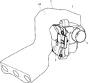
また、本発明の吸気装置は、スロットルボアを画定するスロットルボディと、前記スロットルボアを開閉するスロットルバルブと、前記スロットルバルブを開閉駆動するモータと、前記モータの駆動力を前記スロットルバルブに伝達する動力伝達機構と、一側において前記スロットルボディ及び前記モータを位置づけて保持し、かつ、他側において前記動力伝達機構を位置づけて保持する支持部材と、前記スロットルボアとともに吸気通路を画定する樹脂材料から形成された通路部材とを備えた吸気装置であって、前記通路部材には、前記スロットルボディと前記モータとを収容する収容室が設けられており、前記支持部材は、前記収容室の収容口を閉塞するように前記通路部材に接合されることを特徴とする。
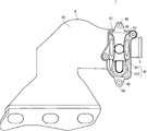
また、本発明は、前記支持部材には前記通路部材に接合されるべく形成された固定部を有し、該固定部が前記通路部材に接合されることによって、前記スロットルボディと前記モータとが収容室の所定位置へ収容されることを特徴とする。
また、本発明は、前記固定部は、弾性変形可能な係合爪を有し、前記支持部材は、前記係合爪を前記通路部材に係合することで前記通路部材に接合されることを特徴とする。
また、本発明は、前記固定部は、外周面に貫通穴を開口させた突部を有し、前記支持部材は、前記貫通穴に挿入され前記通路部材とを係止する係止部材により前記通路部材に接合されることを特徴とする。
また、本発明は、前記通路部材は、インテークマニホールドであることを特徴とする。
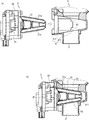
また、本発明は、前記モータと前記収容室との間には、前記収容室への前記モータの挿入方向と逆方向に前記モータを付勢する付勢部材が介装されることを特徴とする。
また、動力伝達機構は、支持部材24の他側に位置付けられて内蔵されている。動力伝達機構は、モータ23の回転軸231に固定された歯車251と、歯車251と噛合した歯車252と、歯車252と一体となって回転する歯車253と、スロットルバルブ22の回転軸221に固定されて歯車253と噛合した歯車254とを備えている。歯車252及び歯車253は、支持部材24に軸支された回転軸に支持されている。
2 スロットル制御装置
21 スロットルボディ
211 スロットルボア
21a 端面
22 スロットルバルブ
23 モータ
24 アクチュエータケース
25,25A,25B 固定部
26,26A,26B 貫通孔
27 スナップフィット
28 係合爪
3 吸気通路
38 突部
381 貫通穴
4 インテークマニホールド
41 収容室
411 収容部
412 収容部
43 接合面
44 サージタンク
45,45A,45B 被固定部
46,46A,46B 挿通孔
47 貫通穴
48 係止溝
6 板バネ
7 ピン
8 抜け止めピン
Claims (7)
- スロットルボアを画定するスロットルボディと、
前記スロットルボアを開閉するスロットルバルブと、
前記スロットルバルブを開閉駆動するモータと、
前記モータの駆動力を前記スロットルバルブに伝達する動力伝達機構と、
一側において前記スロットルボディ及び前記モータを位置づけて保持し、かつ、他側において前記動力伝達機構を位置づけて保持する支持部材と、
前記スロットルボアとともに吸気通路を画定する樹脂材料から形成された通路部材とを備えた吸気装置であって、
前記通路部材には、前記スロットルボディと前記モータとを収容する収容室が設けられ
ており、
前記通路部材の前記収容室には、前記スロットルボア端面と嵌合される嵌合部と、
前記スロットルボディを前記収容室内に案内し、前記スロットルボア端面と前記嵌合部が嵌め合わされるように所定の位置に導く案内面とが設けられていることを特徴とする吸気装置。 - スロットルボアを画定するスロットルボディと、
前記スロットルボアを開閉するスロットルバルブと、
前記スロットルバルブを開閉駆動するモータと、
前記モータの駆動力を前記スロットルバルブに伝達する動力伝達機構と、
一側において前記スロットルボディ及び前記モータを位置づけて保持し、かつ、他側において前記動力伝達機構を位置づけて保持する支持部材と、
前記スロットルボアとともに吸気通路を画定する樹脂材料から形成された通路部材とを備えた吸気装置であって、
前記通路部材には、前記スロットルボディと前記モータとを収容する収容室が設けられており、
前記支持部材は、前記収容室の収容口を閉塞するように前記通路部材に接合されることを特徴とする吸気装置。 - 前記支持部材には前記通路部材に接合されるべく形成された固定部を有し、
該固定部が前記通路部材に接合されることによって、前記スロットルボディと前記モータとが収容室の所定位置へ収容されることを特徴とする請求項1又は2に記載の吸気装置。 - 前記固定部は、弾性変形可能な係合爪を有し、
前記支持部材は、前記係合爪を前記通路部材に係合することで前記通路部材に接合されることを特徴とする請求項3に記載の吸気装置。 - 前記固定部は、外周面に貫通穴を開口させた突部を有し、
前記支持部材は、前記貫通穴に挿入され前記通路部材とを係止する係止部材により前記通路部材に接合されることを特徴とする請求項3に記載の吸気装置。 - 前記通路部材は、インテークマニホールドであることを特徴とする請求項1〜5に記載の吸気装置。
- 前記モータと前記収容室との間には、前記収容室への前記モータの挿入方向と逆方向に前記モータを付勢する付勢部材が介装されることを特徴とする請求項1〜6に記載の吸気装置。
Applications Claiming Priority (3)
| Application Number | Priority Date | Filing Date | Title |
|---|---|---|---|
| JP2011112440 | 2011-05-19 | ||
| JP2011112440 | 2011-05-19 | ||
| PCT/JP2012/062366 WO2012157626A1 (ja) | 2011-05-19 | 2012-05-15 | 吸気装置 |
Publications (2)
| Publication Number | Publication Date |
|---|---|
| JPWO2012157626A1 JPWO2012157626A1 (ja) | 2014-07-31 |
| JP6031438B2 true JP6031438B2 (ja) | 2016-11-24 |
Family
ID=47176943
Family Applications (1)
| Application Number | Title | Priority Date | Filing Date |
|---|---|---|---|
| JP2013515155A Expired - Fee Related JP6031438B2 (ja) | 2011-05-19 | 2012-05-15 | 吸気装置 |
Country Status (5)
| Country | Link |
|---|---|
| US (1) | US9541009B2 (ja) |
| EP (1) | EP2711524A4 (ja) |
| JP (1) | JP6031438B2 (ja) |
| CN (1) | CN103562520B (ja) |
| WO (1) | WO2012157626A1 (ja) |
Citations (7)
| Publication number | Priority date | Publication date | Assignee | Title |
|---|---|---|---|---|
| JPS58146458U (ja) * | 1982-03-26 | 1983-10-01 | 株式会社日本バノツク | 係止具 |
| JPH10103089A (ja) * | 1996-09-25 | 1998-04-21 | Aisan Ind Co Ltd | 吸気装置 |
| JP2001182558A (ja) * | 1999-10-13 | 2001-07-06 | Denso Corp | 内燃機関の吸気制御装置及びその組付方法 |
| JP2003049726A (ja) * | 2001-08-06 | 2003-02-21 | Fuji Heavy Ind Ltd | エンジンの吸気装置 |
| JP2004232594A (ja) * | 2003-01-31 | 2004-08-19 | Denso Corp | 吸気装置 |
| JP2007023954A (ja) * | 2005-07-20 | 2007-02-01 | Denso Corp | 排気ガス再循環装置 |
| JP2009150252A (ja) * | 2007-12-19 | 2009-07-09 | Mikuni Corp | バルブ開度検知装置及びバルブ開閉装置 |
Family Cites Families (18)
| Publication number | Priority date | Publication date | Assignee | Title |
|---|---|---|---|---|
| JPS58146458A (ja) | 1982-02-26 | 1983-09-01 | Fuji Electric Corp Res & Dev Ltd | 横置型多段式サイクロン分離器 |
| EP0911506A3 (en) * | 1997-10-21 | 2000-12-27 | Hitachi, Ltd. | Electronically controlled throttle apparatus for an engine |
| FR2771046B1 (fr) * | 1997-11-17 | 2000-01-14 | Mecaplast Sam | Procede de fabrication de passages d'axes dans une piece moulee en plastique, un moule et utilisation du procede dans un dispositif a volet pour moteurs a combustion interne |
| US6116215A (en) * | 1998-07-16 | 2000-09-12 | The Barber-Colman Company | Integrated throttle valve and actuator |
| US6497245B1 (en) * | 1999-10-13 | 2002-12-24 | Denso Corporation | Intake air controller for internal combustion engine and manufacturing the same |
| US6427655B2 (en) * | 2000-05-31 | 2002-08-06 | Suzuki Kabushiki Kaisha | Intake manifold of outboard motor |
| JP2001346351A (ja) * | 2000-05-31 | 2001-12-14 | Asmo Co Ltd | モータ及びスロットルアクチュエータ |
| EP1283350B1 (en) | 2001-08-06 | 2010-01-20 | Fuji Jukogyo Kabushiki Kaisha | Air intake system of engine |
| DE10156213A1 (de) * | 2001-11-15 | 2003-06-05 | Siemens Ag | Drosselklappenstutzen |
| US20050139800A1 (en) * | 2002-08-22 | 2005-06-30 | Siegfried Deiss | Butterfly valve unit |
| JP4198616B2 (ja) | 2004-02-23 | 2008-12-17 | 愛三工業株式会社 | 電子スロットル装置 |
| JP2006017080A (ja) * | 2004-07-05 | 2006-01-19 | Denso Corp | 内燃機関用吸気制御装置 |
| JP4104594B2 (ja) * | 2004-12-22 | 2008-06-18 | 株式会社ケーヒン | エンジン用吸気制御装置 |
| JP2006214293A (ja) * | 2005-02-01 | 2006-08-17 | Mikuni Corp | スロットル装置、燃料供給装置およびエンジン |
| JP4556864B2 (ja) * | 2005-12-26 | 2010-10-06 | 株式会社デンソー | 内燃機関用吸気装置 |
| EP1939432A1 (en) * | 2006-12-29 | 2008-07-02 | MAGNETI MARELLI POWERTRAIN S.p.A. | Servo controlled valve with cylindrical shutter for adjusting the intake air flow rate in an internal combustion engine |
| JP2010116794A (ja) | 2008-11-11 | 2010-05-27 | Honda Motor Co Ltd | 内燃機関の吸気装置 |
| EP2730820A1 (en) * | 2011-07-04 | 2014-05-14 | Mikuni Corporation | Gasket and throttle body |
-
2012
- 2012-05-15 EP EP12785109.5A patent/EP2711524A4/en not_active Withdrawn
- 2012-05-15 CN CN201280023717.7A patent/CN103562520B/zh not_active Expired - Fee Related
- 2012-05-15 JP JP2013515155A patent/JP6031438B2/ja not_active Expired - Fee Related
- 2012-05-15 WO PCT/JP2012/062366 patent/WO2012157626A1/ja not_active Ceased
- 2012-05-15 US US14/118,064 patent/US9541009B2/en not_active Expired - Fee Related
Patent Citations (7)
| Publication number | Priority date | Publication date | Assignee | Title |
|---|---|---|---|---|
| JPS58146458U (ja) * | 1982-03-26 | 1983-10-01 | 株式会社日本バノツク | 係止具 |
| JPH10103089A (ja) * | 1996-09-25 | 1998-04-21 | Aisan Ind Co Ltd | 吸気装置 |
| JP2001182558A (ja) * | 1999-10-13 | 2001-07-06 | Denso Corp | 内燃機関の吸気制御装置及びその組付方法 |
| JP2003049726A (ja) * | 2001-08-06 | 2003-02-21 | Fuji Heavy Ind Ltd | エンジンの吸気装置 |
| JP2004232594A (ja) * | 2003-01-31 | 2004-08-19 | Denso Corp | 吸気装置 |
| JP2007023954A (ja) * | 2005-07-20 | 2007-02-01 | Denso Corp | 排気ガス再循環装置 |
| JP2009150252A (ja) * | 2007-12-19 | 2009-07-09 | Mikuni Corp | バルブ開度検知装置及びバルブ開閉装置 |
Also Published As
| Publication number | Publication date |
|---|---|
| CN103562520A (zh) | 2014-02-05 |
| EP2711524A1 (en) | 2014-03-26 |
| CN103562520B (zh) | 2016-03-30 |
| JPWO2012157626A1 (ja) | 2014-07-31 |
| WO2012157626A1 (ja) | 2012-11-22 |
| EP2711524A4 (en) | 2014-12-03 |
| US9541009B2 (en) | 2017-01-10 |
| US20140102410A1 (en) | 2014-04-17 |
Similar Documents
| Publication | Publication Date | Title |
|---|---|---|
| JP5122419B2 (ja) | キャニスタの付属部品取付け構造 | |
| JP5962620B2 (ja) | アクチュエータの製造方法 | |
| KR100790670B1 (ko) | 하우징 내에 수용된 액츄에이터를 위한 지지 장치 | |
| US9752538B2 (en) | Drive arrangement for an assembly of an internal combustion engine, and exhaust-gas recirculation valve | |
| JP4093173B2 (ja) | 内燃機関用スロットル制御装置 | |
| JP5971276B2 (ja) | アクチュエータおよびその組付方法 | |
| JP2006022660A (ja) | 内燃機関用吸気制御装置 | |
| US11092086B2 (en) | Throttle valve device | |
| US11867309B2 (en) | Throttle valve device and method for magnetizing the same | |
| CN112443695B (zh) | 节流阀装置 | |
| JP2012041900A (ja) | 吸気系部品の締結構造 | |
| JP5278155B2 (ja) | シリンダヘッドカバー | |
| JP2012159052A (ja) | 吸気制御装置 | |
| JP6031438B2 (ja) | 吸気装置 | |
| JP2013104391A (ja) | スロットル装置 | |
| JP5687872B2 (ja) | バルブ取付構造 | |
| JP2010116794A (ja) | 内燃機関の吸気装置 | |
| JP6203044B2 (ja) | 吸気制御弁の組付構造及び組付方法 | |
| CN106662258A (zh) | 尤其用于机动车辆的具有止挡垫圈的流体流通阀和用于制造这种阀的方法 | |
| JP6347847B2 (ja) | 内燃機関の流体通路ケーシングに制御弁を取り付けるためのユニット | |
| JP4542542B2 (ja) | 燃料噴射モジュール | |
| KR101498818B1 (ko) | 전자식 스로틀 어셈블리 | |
| JP5292332B2 (ja) | 内燃機関用吸気制御装置 | |
| CN113227558B (zh) | 进气装置 | |
| JP5391310B2 (ja) | 燃料噴射弁 |
Legal Events
| Date | Code | Title | Description |
|---|---|---|---|
| A621 | Written request for application examination |
Free format text: JAPANESE INTERMEDIATE CODE: A621 Effective date: 20150514 |
|
| A131 | Notification of reasons for refusal |
Free format text: JAPANESE INTERMEDIATE CODE: A131 Effective date: 20160426 |
|
| A521 | Request for written amendment filed |
Free format text: JAPANESE INTERMEDIATE CODE: A523 Effective date: 20160623 |
|
| TRDD | Decision of grant or rejection written | ||
| A01 | Written decision to grant a patent or to grant a registration (utility model) |
Free format text: JAPANESE INTERMEDIATE CODE: A01 Effective date: 20160927 |
|
| A61 | First payment of annual fees (during grant procedure) |
Free format text: JAPANESE INTERMEDIATE CODE: A61 Effective date: 20161024 |
|
| R150 | Certificate of patent or registration of utility model |
Ref document number: 6031438 Country of ref document: JP Free format text: JAPANESE INTERMEDIATE CODE: R150 |
|
| R250 | Receipt of annual fees |
Free format text: JAPANESE INTERMEDIATE CODE: R250 |
|
| R250 | Receipt of annual fees |
Free format text: JAPANESE INTERMEDIATE CODE: R250 |
|
| R250 | Receipt of annual fees |
Free format text: JAPANESE INTERMEDIATE CODE: R250 |
|
| R250 | Receipt of annual fees |
Free format text: JAPANESE INTERMEDIATE CODE: R250 |
|
| LAPS | Cancellation because of no payment of annual fees |