JP6033237B2 - 電気的な接続装置用の金属部品 - Google Patents
電気的な接続装置用の金属部品 Download PDFInfo
- Publication number
- JP6033237B2 JP6033237B2 JP2013554810A JP2013554810A JP6033237B2 JP 6033237 B2 JP6033237 B2 JP 6033237B2 JP 2013554810 A JP2013554810 A JP 2013554810A JP 2013554810 A JP2013554810 A JP 2013554810A JP 6033237 B2 JP6033237 B2 JP 6033237B2
- Authority
- JP
- Japan
- Prior art keywords
- leg
- side wall
- metal part
- clamp
- contact leg
- Prior art date
- Legal status (The legal status is an assumption and is not a legal conclusion. Google has not performed a legal analysis and makes no representation as to the accuracy of the status listed.)
- Expired - Fee Related
Links
- 239000002184 metal Substances 0.000 title claims description 173
- 229910052751 metal Inorganic materials 0.000 title claims description 173
- 239000004020 conductor Substances 0.000 claims description 64
- 238000005452 bending Methods 0.000 claims description 44
- 238000004519 manufacturing process Methods 0.000 claims description 16
- 238000003825 pressing Methods 0.000 claims description 6
- 230000008878 coupling Effects 0.000 claims description 3
- 238000010168 coupling process Methods 0.000 claims description 3
- 238000005859 coupling reaction Methods 0.000 claims description 3
- 230000001154 acute effect Effects 0.000 claims description 2
- 238000005520 cutting process Methods 0.000 claims 1
- 238000000034 method Methods 0.000 description 13
- 239000000463 material Substances 0.000 description 7
- 238000004080 punching Methods 0.000 description 2
- 230000006641 stabilisation Effects 0.000 description 2
- 238000011105 stabilization Methods 0.000 description 2
- 230000005540 biological transmission Effects 0.000 description 1
- 238000010276 construction Methods 0.000 description 1
- 230000000994 depressogenic effect Effects 0.000 description 1
- 150000002739 metals Chemical class 0.000 description 1
- 239000011435 rock Substances 0.000 description 1
- 238000004513 sizing Methods 0.000 description 1
Images


Classifications
-
- H—ELECTRICITY
- H01—ELECTRIC ELEMENTS
- H01R—ELECTRICALLY-CONDUCTIVE CONNECTIONS; STRUCTURAL ASSOCIATIONS OF A PLURALITY OF MUTUALLY-INSULATED ELECTRICAL CONNECTING ELEMENTS; COUPLING DEVICES; CURRENT COLLECTORS
- H01R13/00—Details of coupling devices of the kinds covered by groups H01R12/70 or H01R24/00 - H01R33/00
- H01R13/62—Means for facilitating engagement or disengagement of coupling parts or for holding them in engagement
- H01R13/629—Additional means for facilitating engagement or disengagement of coupling parts, e.g. aligning or guiding means, levers, gas pressure electrical locking indicators, manufacturing tolerances
-
- H—ELECTRICITY
- H01—ELECTRIC ELEMENTS
- H01R—ELECTRICALLY-CONDUCTIVE CONNECTIONS; STRUCTURAL ASSOCIATIONS OF A PLURALITY OF MUTUALLY-INSULATED ELECTRICAL CONNECTING ELEMENTS; COUPLING DEVICES; CURRENT COLLECTORS
- H01R4/00—Electrically-conductive connections between two or more conductive members in direct contact, i.e. touching one another; Means for effecting or maintaining such contact; Electrically-conductive connections having two or more spaced connecting locations for conductors and using contact members penetrating insulation
- H01R4/28—Clamped connections, spring connections
- H01R4/48—Clamped connections, spring connections utilising a spring, clip, or other resilient member
- H01R4/4809—Clamped connections, spring connections utilising a spring, clip, or other resilient member using a leaf spring to bias the conductor toward the busbar
- H01R4/4846—Busbar details
- H01R4/485—Single busbar common to multiple springs
-
- H—ELECTRICITY
- H01—ELECTRIC ELEMENTS
- H01R—ELECTRICALLY-CONDUCTIVE CONNECTIONS; STRUCTURAL ASSOCIATIONS OF A PLURALITY OF MUTUALLY-INSULATED ELECTRICAL CONNECTING ELEMENTS; COUPLING DEVICES; CURRENT COLLECTORS
- H01R43/00—Apparatus or processes specially adapted for manufacturing, assembling, maintaining, or repairing of line connectors or current collectors or for joining electric conductors
- H01R43/16—Apparatus or processes specially adapted for manufacturing, assembling, maintaining, or repairing of line connectors or current collectors or for joining electric conductors for manufacturing contact members, e.g. by punching and by bending
-
- H—ELECTRICITY
- H01—ELECTRIC ELEMENTS
- H01R—ELECTRICALLY-CONDUCTIVE CONNECTIONS; STRUCTURAL ASSOCIATIONS OF A PLURALITY OF MUTUALLY-INSULATED ELECTRICAL CONNECTING ELEMENTS; COUPLING DEVICES; CURRENT COLLECTORS
- H01R4/00—Electrically-conductive connections between two or more conductive members in direct contact, i.e. touching one another; Means for effecting or maintaining such contact; Electrically-conductive connections having two or more spaced connecting locations for conductors and using contact members penetrating insulation
- H01R4/28—Clamped connections, spring connections
- H01R4/48—Clamped connections, spring connections utilising a spring, clip, or other resilient member
- H01R4/4809—Clamped connections, spring connections utilising a spring, clip, or other resilient member using a leaf spring to bias the conductor toward the busbar
- H01R4/48185—Clamped connections, spring connections utilising a spring, clip, or other resilient member using a leaf spring to bias the conductor toward the busbar adapted for axial insertion of a wire end
- H01R4/4819—Clamped connections, spring connections utilising a spring, clip, or other resilient member using a leaf spring to bias the conductor toward the busbar adapted for axial insertion of a wire end the spring shape allowing insertion of the conductor end when the spring is unbiased
- H01R4/4821—Single-blade spring
-
- H—ELECTRICITY
- H01—ELECTRIC ELEMENTS
- H01R—ELECTRICALLY-CONDUCTIVE CONNECTIONS; STRUCTURAL ASSOCIATIONS OF A PLURALITY OF MUTUALLY-INSULATED ELECTRICAL CONNECTING ELEMENTS; COUPLING DEVICES; CURRENT COLLECTORS
- H01R4/00—Electrically-conductive connections between two or more conductive members in direct contact, i.e. touching one another; Means for effecting or maintaining such contact; Electrically-conductive connections having two or more spaced connecting locations for conductors and using contact members penetrating insulation
- H01R4/28—Clamped connections, spring connections
- H01R4/48—Clamped connections, spring connections utilising a spring, clip, or other resilient member
- H01R4/4809—Clamped connections, spring connections utilising a spring, clip, or other resilient member using a leaf spring to bias the conductor toward the busbar
- H01R4/4828—Spring-activating arrangements mounted on or integrally formed with the spring housing
- H01R4/4833—Sliding arrangements, e.g. sliding button
-
- H—ELECTRICITY
- H01—ELECTRIC ELEMENTS
- H01R—ELECTRICALLY-CONDUCTIVE CONNECTIONS; STRUCTURAL ASSOCIATIONS OF A PLURALITY OF MUTUALLY-INSULATED ELECTRICAL CONNECTING ELEMENTS; COUPLING DEVICES; CURRENT COLLECTORS
- H01R4/00—Electrically-conductive connections between two or more conductive members in direct contact, i.e. touching one another; Means for effecting or maintaining such contact; Electrically-conductive connections having two or more spaced connecting locations for conductors and using contact members penetrating insulation
- H01R4/28—Clamped connections, spring connections
- H01R4/48—Clamped connections, spring connections utilising a spring, clip, or other resilient member
- H01R4/4809—Clamped connections, spring connections utilising a spring, clip, or other resilient member using a leaf spring to bias the conductor toward the busbar
- H01R4/4828—Spring-activating arrangements mounted on or integrally formed with the spring housing
- H01R4/4835—Mechanically bistable arrangements, e.g. locked by the housing when the spring is biased
-
- Y—GENERAL TAGGING OF NEW TECHNOLOGICAL DEVELOPMENTS; GENERAL TAGGING OF CROSS-SECTIONAL TECHNOLOGIES SPANNING OVER SEVERAL SECTIONS OF THE IPC; TECHNICAL SUBJECTS COVERED BY FORMER USPC CROSS-REFERENCE ART COLLECTIONS [XRACs] AND DIGESTS
- Y10—TECHNICAL SUBJECTS COVERED BY FORMER USPC
- Y10T—TECHNICAL SUBJECTS COVERED BY FORMER US CLASSIFICATION
- Y10T29/00—Metal working
- Y10T29/49—Method of mechanical manufacture
- Y10T29/49002—Electrical device making
- Y10T29/49117—Conductor or circuit manufacturing
- Y10T29/49204—Contact or terminal manufacturing
Landscapes
- Engineering & Computer Science (AREA)
- Manufacturing & Machinery (AREA)
- Coupling Device And Connection With Printed Circuit (AREA)
- Manufacturing Of Electrical Connectors (AREA)
- Clamps And Clips (AREA)
Description
Claims (10)
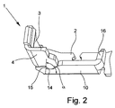
- ベース脚部(2)と、該ベース脚部(2)に対してほぼ垂直に配置されているコンタクト脚部(3)と、少なくとも1つの側壁(4)とを備えていて、前記コンタクト脚部(3)は、押圧ばねとして作用するV字形又はU字形のクランプばね(5)のクランプ脚部(6)と共に、接続しようとする電気的な導体用のばね力クランプ接続部を形成する、少なくとも1つのストリップされた導体端部を接続する電気的な接続装置用の金属部品であって、
前記コンタクト脚部(3)は前記ベース脚部(2)から折り曲げられていて、前記側壁(4)は前記コンタクト脚部(3)から前記ベース脚部(2)に向かって折り曲げられていて、前記コンタクト脚部(3)と前記ベース脚部(2)との間の曲げエッジ(8)が、前記コンタクト脚部(3)及び前記ベース脚部(2)の長手方向延在部に対して垂直方向に延びている一方で、前記コンタクト脚部(3)と前記側壁(4)との間の曲げエッジ(9)が、前記コンタクト脚部(3)の長手方向延在部に対して平行に延びており、
前記ベース脚部(2)から折り曲げられている第2の側壁(10)が設けられていて、該第2の側壁(10)と前記ベース脚部(2)との間の曲げエッジ(11)は、前記第2の側壁(10)及び前記ベース脚部(2)の長手方向延在部に対して平行に延びていて、前記2つの側壁(4,10)は、前記金属部品(1)の同じ側に配置されていることを特徴とする、少なくとも1つのストリップされた導体端部を接続する電気的な接続装置用の金属部品。 - 前記2つの側壁(4,10)の互いに向かい合っている端部領域(12,13)が、形状結合により互いに結合されて形成されていることを特徴とする、請求項1記載の金属部品。
- 前記2つの側壁(4,10)の互いに向かい合っている端部領域(12,13)は夫々、前記ベース脚部(2)に対して所定の鋭角αを成して延びているエッジ(14,15)を有することを特徴とする、請求項2記載の金属部品。
- 前記第2の側壁(10)の第1の側壁(4)とは反対側にある端部(16)は、前記第2の側壁(10)から折り曲げられていて、前記第2の側壁(10)と前記端部(16)との間の曲げエッジ(17)は、前記第2の側壁(10)の長手方向延在部に対して垂直に延びていて、前記端部(16)は前記コンタクト脚部(3)に相対していることを特徴とする、請求項1から3までのいずれか1項記載の金属部品。
- 前記コンタクト脚部(3)の前記第1の側壁(4)とは反対側にある長辺に凹部(18)が設けられていて、前記第1の側壁(4)のコンタクト脚部(3)とは反対側にある長辺に凸部(19)が設けられていて、前記凹部(18)の輪郭と、前記凸部(19)の輪郭とは互いに適合されていることを特徴とする、請求項1から4までのいずれか1項記載の金属部品。
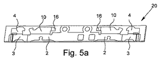
- 平坦な金属ストリップ(20)から、電気的な接続装置用の金属部品(1)を製造する方法であって、前記金属部品(1)は、ベース脚部(2)と、コンタクト脚部(3)と、少なくとも1つの側壁(4)とを有する、平坦な金属ストリップから、電気的な接続装置用の金属部品を製造する方法において、
−前記金属部品(1)の輪郭を抜き加工するステップと、
−前記側壁(4)と前記コンタクト脚部(3)との間の、前記コンタクト脚部(3)の長手方向延在部に対して平行に延びていて、かつ前記金属ストリップ(20)の搬送方向(T)に対して垂直に延びている曲げエッジ(9)を中心として、第1の側壁(4)を曲げ加工するステップと、
−前記コンタクト脚部(3)及び前記ベース脚部(2)の長手方向延在部に対して垂直に延びていて、かつ前記金属ストリップ(20)の搬送方向(T)に対して平行に延びている曲げエッジ(8)を中心として前記コンタクト脚部(3)を曲げ加工するステップと、
を有し、
前記第1の側壁(4)も配置されている、前記金属ストリップ(20)の側において、第2の側壁(10)を、該第2の側壁(10)と前記ベース脚部(2)との間の曲げエッジ(11)を中心として曲げ、前記曲げエッジ(11)は、前記第2の側壁(10)の長手方向延在部に対して平行に延びていて、かつ前記金属ストリップ(20)の搬送方向(T)に対して垂直に延びていることを特徴とする、平坦な金属ストリップから、電気的な接続装置用の金属部品を製造する方法。 - 前記第2の側壁(10)の曲げ加工前に、前記第2の側壁(10)の前記第1の側壁(4)とは反対側にある端部(16)を、前記第2の側壁(10)から、前記端部(16)が前記コンタクト脚部(3)に相対するまで曲げエッジ(17)を中心に曲げ、該曲げエッジ(17)は、前記第2の側壁(10)と前記端部(16)との間において前記第2の側壁(10)の長手方向延在部に対して垂直に延びていて、かつ前記金属ストリップ(20)の搬送方向(T)に対して平行に延びていることを特徴とする、請求項6記載の金属部品を製造する方法。
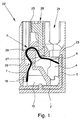
- ストリップされた導体端部を接続する接続装置であって、押圧ばねとして前記導体端部に作用する、クランプ脚部(6)及び当接脚部(7)を有するV字形又はU字形のクランプばね(5)を備え、かつ請求項1から5までのいずれか1項記載の金属部品(1)を備え、前記金属部品(1)のコンタクト脚部(3)は、前記クランプばね(5)のクランプ脚部(6)と共に、接続しようとする電気的な導体用のばね力クランプ接続部を形成することを特徴とする、ストリップされた導体端部を接続する接続装置。
- ハウジング(23)を備えた電気的な接続端子であって、クランプ脚部(6)及び当接脚部(7)を有する、押圧ばねとして導体端部に作用する少なくとも1つのV字形又はU字形のクランプばね(5)を備え、かつ請求項1から5までのいずれか1項記載の少なくとも1つの金属部品(1)を備え、金属部品(1)のコンタクト脚部(3)は、クランプばね(5)の前記クランプ脚部(6)と共に、接続しようとする電気的な導体用のばね力クランプ接続部を形成し、前記ハウジング(23)に、接続しようとする導体を導入する少なくとも1つの導体導入開口(24)と、少なくとも1つの操作開口(25)とが形成されていることを特徴とする、ハウジングを備えた電気的な接続端子。
- 前記操作開口(25)に操作ボタン(26)が配置されていて、該操作ボタン(26)は、ばね力クランプ接続部が閉鎖されている第1の位置から、前記操作ボタン(26)の、前記クランプ脚部(6)寄りの第1の端部(27)が、前記クランプばね(5)のばね力に抗して前記クランプ脚部(6)を変位させて、前記ばね力クランプ接続部が開放されている第2の位置に移動可能であり、
前記ハウジング(23)に段部(28)が形成されていて、かつ前記操作ボタン(26)に少なくとも1つの突出部(29)が形成されていて、前記操作ボタン(26)は、前記突出部(29)と前記段部(28)とが互いに係止されて、前記操作ボタン(26)がその第2の位置に保持されている状態に移動可能であることを特徴とする、請求項9記載の電気的な接続端子。
Applications Claiming Priority (3)
| Application Number | Priority Date | Filing Date | Title |
|---|---|---|---|
| DE102011012021A DE102011012021A1 (de) | 2011-02-22 | 2011-02-22 | Metallteil für eine elektronische Anschlussvorrichtung |
| DE102011012021.1 | 2011-02-22 | ||
| PCT/EP2012/000761 WO2012113544A2 (de) | 2011-02-22 | 2012-02-22 | Metallteil für eine elektrische anschlussvorrichtung |
Publications (2)
| Publication Number | Publication Date |
|---|---|
| JP2014509443A JP2014509443A (ja) | 2014-04-17 |
| JP6033237B2 true JP6033237B2 (ja) | 2016-11-30 |
Family
ID=45929481
Family Applications (1)
| Application Number | Title | Priority Date | Filing Date |
|---|---|---|---|
| JP2013554810A Expired - Fee Related JP6033237B2 (ja) | 2011-02-22 | 2012-02-22 | 電気的な接続装置用の金属部品 |
Country Status (7)
| Country | Link |
|---|---|
| US (1) | US9184540B2 (ja) |
| EP (1) | EP2678904B1 (ja) |
| JP (1) | JP6033237B2 (ja) |
| CN (1) | CN103392271B (ja) |
| DE (1) | DE102011012021A1 (ja) |
| ES (1) | ES2727036T3 (ja) |
| WO (1) | WO2012113544A2 (ja) |
Families Citing this family (17)
| Publication number | Priority date | Publication date | Assignee | Title |
|---|---|---|---|---|
| DE202013100740U1 (de) | 2013-02-19 | 2013-03-08 | Weidmüller Interface GmbH & Co. KG | Federkraftklemme für Leiter |
| DE202014102521U1 (de) | 2014-05-28 | 2015-09-03 | Weidmüller Interface GmbH & Co. KG | Direktsteck-Druckfederklemme mit Haltefeder |
| TWM502983U (zh) | 2014-12-04 | 2015-06-11 | Switchlab Inc | 軌道型電聯接端子之導電接線結構 |
| DE102015100823B4 (de) * | 2015-01-21 | 2021-12-09 | Phoenix Contact Gmbh & Co. Kg | Elektrische Anschlussklemme |
| DE202015008280U1 (de) | 2015-12-01 | 2015-12-14 | Switchlab (Shanghai) Co., Ltd. | Verbesserter Aufbau einer elektrischen Anschlussklemme mit Pfad |
| DE102016121967A1 (de) * | 2016-11-16 | 2018-05-30 | Phoenix Contact Gmbh & Co. Kg | Elektrische Anschluss- sowie Verbindungsklemme |
| JP2018107079A (ja) * | 2016-12-28 | 2018-07-05 | オムロン株式会社 | 端子台 |
| DE102017109694B4 (de) * | 2017-05-05 | 2022-10-06 | Wago Verwaltungsgesellschaft Mbh | Anschlussklemme |
| DE102017110060B4 (de) * | 2017-05-10 | 2022-07-14 | Conrad Stanztechnik Gmbh | Verfahren zum Herstellen einer Anordnung und Anordnung mit einer Stromschiene für eine Anschlussklemme zum Kontaktieren mehrerer elektrischer Leiter und elektrische Anschlussklemme |
| TWI666836B (zh) * | 2018-03-16 | 2019-07-21 | 進聯工業股份有限公司 | 電性接線裝置之導電組件結構 |
| JP6927423B2 (ja) * | 2018-05-08 | 2021-08-25 | 富士電機機器制御株式会社 | 接続端子台、電気機器 |
| WO2020115756A1 (en) * | 2018-12-03 | 2020-06-11 | Connectwell Industries Pvt. Ltd. | Connecting terminal |
| BE1027120B1 (de) * | 2019-03-13 | 2020-10-14 | Phoenix Contact Gmbh & Co | Leiteranschlussklemme mit einem Betätigungselement mit angepasster Druckfläche |
| DE102019108291A1 (de) * | 2019-03-29 | 2020-10-01 | Wago Verwaltungsgesellschaft Mbh | Leiteranschlussklemme |
| JP7255396B2 (ja) * | 2019-07-08 | 2023-04-11 | 住友電装株式会社 | 電気接続箱 |
| EP4037104B1 (en) | 2021-01-27 | 2024-11-20 | Tyco Electronics France SAS | Terminal block comprising a conductive bar with a lateral portion |
| DE102022102909A1 (de) | 2022-02-08 | 2023-08-10 | Wieland Electric Gmbh | Kontaktschiene, Stanzstreifen, Kontaktanschluss und Isoliergehäuse |
Family Cites Families (13)
| Publication number | Priority date | Publication date | Assignee | Title |
|---|---|---|---|---|
| DE4231244C2 (de) * | 1992-09-18 | 1995-11-02 | Phoenix Contact Gmbh & Co | Elektrische Anschlußklemme, insbesondere Reihenklemme |
| ES2216086T3 (es) * | 1997-08-14 | 2004-10-16 | PHOENIX CONTACT GMBH & CO. KG | Borne electrico de fuerza elastica. |
| JP3854458B2 (ja) * | 2000-10-20 | 2006-12-06 | 矢崎総業株式会社 | 端子金具と端子金具の組立方法 |
| EP1353407B1 (de) * | 2002-04-12 | 2011-01-19 | Weidmüller Interface GmbH & Co. KG | Anschlussvorrichtung für Leiter |
| DE10355195B4 (de) * | 2003-11-26 | 2007-03-15 | Wieland Electric Gmbh | Leiteranschluss |
| DE202005005369U1 (de) | 2004-11-13 | 2006-03-16 | Weidmüller Interface GmbH & Co. KG | Anschlußvorrichtung zum Direktsteckanschluß von Leiterenden und elektrisches Gerät mit einer derartigen Anschlußvorrichtung |
| DE102006058985A1 (de) * | 2006-12-14 | 2008-06-19 | Abb Ag | Federzugklemme |
| DE202007012429U1 (de) | 2007-09-05 | 2007-10-31 | Conrad Stanztechnik Gmbh | Stromschienenanordnung für eine elektrische Anschlussvorrichtung sowie Neutral-Leiter-Schutzklemme, Schutzleiterklemme und Reihenklemme |
| CN101459288B (zh) * | 2007-12-14 | 2010-12-22 | 浙江正泰建筑电器有限公司 | 快速接/卸导线的端子结构 |
| CN201142366Y (zh) * | 2008-01-11 | 2008-10-29 | 乐清市中远电子有限公司 | 水平进线型接线端子 |
| ITMI20080673A1 (it) * | 2008-04-15 | 2009-10-16 | Morsettitalia Spa | Elemento elastico per la trattenuta di fili elettrici e morsetto comprendente tale elemento elastico |
| DE102008039232B4 (de) | 2008-08-22 | 2019-02-28 | Phoenix Contact Gmbh & Co. Kg | Elektrische Anschlußklemme |
| DE102009050366A1 (de) * | 2009-10-22 | 2011-04-28 | Phoenix Contact Gmbh & Co. Kg | Steckverbindung zur Aufnahme eines starren Leiterendes |
-
2011
- 2011-02-22 DE DE102011012021A patent/DE102011012021A1/de active Pending
-
2012
- 2012-02-22 CN CN201280009955.2A patent/CN103392271B/zh active Active
- 2012-02-22 ES ES12712058T patent/ES2727036T3/es active Active
- 2012-02-22 EP EP12712058.2A patent/EP2678904B1/de active Active
- 2012-02-22 US US13/985,717 patent/US9184540B2/en not_active Expired - Fee Related
- 2012-02-22 JP JP2013554810A patent/JP6033237B2/ja not_active Expired - Fee Related
- 2012-02-22 WO PCT/EP2012/000761 patent/WO2012113544A2/de not_active Ceased
Also Published As
| Publication number | Publication date |
|---|---|
| CN103392271B (zh) | 2016-08-31 |
| US9184540B2 (en) | 2015-11-10 |
| JP2014509443A (ja) | 2014-04-17 |
| WO2012113544A3 (de) | 2013-04-11 |
| US20130330985A1 (en) | 2013-12-12 |
| ES2727036T3 (es) | 2019-10-11 |
| DE102011012021A1 (de) | 2012-08-23 |
| EP2678904A2 (de) | 2014-01-01 |
| WO2012113544A2 (de) | 2012-08-30 |
| CN103392271A (zh) | 2013-11-13 |
| EP2678904B1 (de) | 2019-03-20 |
Similar Documents
| Publication | Publication Date | Title |
|---|---|---|
| JP6033237B2 (ja) | 電気的な接続装置用の金属部品 | |
| US12126130B2 (en) | Spring-loaded terminal for conductor | |
| CN101790819B (zh) | 电触头 | |
| US10615537B2 (en) | Stackable electrical connector and housing for the same | |
| US5540603A (en) | Female contact | |
| US8033872B2 (en) | Contact terminal for test socket | |
| CN203721935U (zh) | 用于连接导线的连接端子 | |
| FI90601C (fi) | Sähköinen lattaliitin | |
| JP2020004718A (ja) | 直接差し込み式コネクタと直接差し込み式接続 | |
| JPS5914277A (ja) | 電気コネクタ | |
| JPS5921582U (ja) | レセプタクル端子 | |
| JP2005183160A (ja) | 雌コンタクト | |
| KR101680273B1 (ko) | 커넥터용 플러그 터미널 | |
| JP2004362973A (ja) | 端子金具 | |
| JP7121913B2 (ja) | 端子、および端子付き電線 | |
| US7798846B2 (en) | Electrical connector assembly with a jumper device | |
| US4447102A (en) | Electrical connector assemblies | |
| US10008806B2 (en) | Lever-type connector capable of operability | |
| KR101964206B1 (ko) | 스플라이스 조인트 단자 | |
| CN101005171B (zh) | 端子接头及设置有该端子接头的连接器 | |
| CN204991978U (zh) | 具扣合结构的端子连接器 | |
| KR101941073B1 (ko) | 커넥터 | |
| JP2004207156A (ja) | 圧接端子およびジョイントコネクタ | |
| KR20100070892A (ko) | 커넥터 및 이를 포함한 커넥터 어셈블리 | |
| CN106486792A (zh) | 具扣合结构的端子座 |
Legal Events
| Date | Code | Title | Description |
|---|---|---|---|
| A621 | Written request for application examination |
Free format text: JAPANESE INTERMEDIATE CODE: A621 Effective date: 20140116 |
|
| A131 | Notification of reasons for refusal |
Free format text: JAPANESE INTERMEDIATE CODE: A131 Effective date: 20141027 |
|
| A601 | Written request for extension of time |
Free format text: JAPANESE INTERMEDIATE CODE: A601 Effective date: 20150127 |
|
| A521 | Request for written amendment filed |
Free format text: JAPANESE INTERMEDIATE CODE: A523 Effective date: 20150225 |
|
| A131 | Notification of reasons for refusal |
Free format text: JAPANESE INTERMEDIATE CODE: A131 Effective date: 20150608 |
|
| A521 | Request for written amendment filed |
Free format text: JAPANESE INTERMEDIATE CODE: A523 Effective date: 20150904 |
|
| A131 | Notification of reasons for refusal |
Free format text: JAPANESE INTERMEDIATE CODE: A131 Effective date: 20160208 |
|
| RD13 | Notification of appointment of power of sub attorney |
Free format text: JAPANESE INTERMEDIATE CODE: A7433 Effective date: 20160419 |
|
| A521 | Request for written amendment filed |
Free format text: JAPANESE INTERMEDIATE CODE: A523 Effective date: 20160428 |
|
| A521 | Request for written amendment filed |
Free format text: JAPANESE INTERMEDIATE CODE: A821 Effective date: 20160419 |
|
| TRDD | Decision of grant or rejection written | ||
| A01 | Written decision to grant a patent or to grant a registration (utility model) |
Free format text: JAPANESE INTERMEDIATE CODE: A01 Effective date: 20160926 |
|
| A61 | First payment of annual fees (during grant procedure) |
Free format text: JAPANESE INTERMEDIATE CODE: A61 Effective date: 20161025 |
|
| R150 | Certificate of patent or registration of utility model |
Ref document number: 6033237 Country of ref document: JP Free format text: JAPANESE INTERMEDIATE CODE: R150 |
|
| R250 | Receipt of annual fees |
Free format text: JAPANESE INTERMEDIATE CODE: R250 |
|
| R250 | Receipt of annual fees |
Free format text: JAPANESE INTERMEDIATE CODE: R250 |
|
| R250 | Receipt of annual fees |
Free format text: JAPANESE INTERMEDIATE CODE: R250 |
|
| LAPS | Cancellation because of no payment of annual fees |