JP6042017B1 - Electronics - Google Patents
Electronics Download PDFInfo
- Publication number
- JP6042017B1 JP6042017B1 JP2016125844A JP2016125844A JP6042017B1 JP 6042017 B1 JP6042017 B1 JP 6042017B1 JP 2016125844 A JP2016125844 A JP 2016125844A JP 2016125844 A JP2016125844 A JP 2016125844A JP 6042017 B1 JP6042017 B1 JP 6042017B1
- Authority
- JP
- Japan
- Prior art keywords
- contact
- reading unit
- magnetic
- housing
- type
- Prior art date
- Legal status (The legal status is an assumption and is not a legal conclusion. Google has not performed a legal analysis and makes no representation as to the accuracy of the status listed.)
- Expired - Fee Related
Links
Images



Classifications
-
- G—PHYSICS
- G06—COMPUTING OR CALCULATING; COUNTING
- G06K—GRAPHICAL DATA READING; PRESENTATION OF DATA; RECORD CARRIERS; HANDLING RECORD CARRIERS
- G06K7/00—Methods or arrangements for sensing record carriers, e.g. for reading patterns
Landscapes
- Engineering & Computer Science (AREA)
- Artificial Intelligence (AREA)
- Computer Vision & Pattern Recognition (AREA)
- Physics & Mathematics (AREA)
- General Physics & Mathematics (AREA)
- Theoretical Computer Science (AREA)
- Conveying Record Carriers (AREA)
- Cash Registers Or Receiving Machines (AREA)
Abstract
【課題】カードの決済機能を有するコンパクトな電子機器を提供する。【解決手段】電子機器1は、第1の側面26とこの第1の側面26に隣接する第2の側面23とこれらの側面26,23が交わる角隅部27とを有する筐体2と、接触型IC読み取り部4及び/又は非接触型IC読み取り部5と、磁気読み取り部6とを備える。接触型IC読み取り部4及び/又は非接触型IC読み取り部5は、筐体2の第1の側面26の側に配置され、磁気読み取り部6は、磁気カードの磁気記録部から磁気情報を取得する磁気センサ61と、磁気カードの磁気記録部を磁気センサ61が走査するために筐体2に設けられる磁気カード用挿入溝62と、を備え、磁気カード用挿入溝62は、角隅部27において、第2の側面23上の第2の位置P2から第1の側面26上の第1の位置P1まで直線状に延びる底面621を有する。【選択図】図2A compact electronic device having a card payment function is provided. An electronic device includes a housing having a first side surface, a second side surface adjacent to the first side surface, and a corner portion where the side surfaces intersect. A contact IC reading unit 4 and / or a non-contact IC reading unit 5 and a magnetic reading unit 6 are provided. The contact-type IC reading unit 4 and / or the non-contact-type IC reading unit 5 are arranged on the first side surface 26 side of the housing 2, and the magnetic reading unit 6 acquires magnetic information from the magnetic recording unit of the magnetic card. And a magnetic card insertion groove 62 provided in the housing 2 in order for the magnetic sensor 61 to scan the magnetic recording portion of the magnetic card. , The bottom surface 621 linearly extends from the second position P2 on the second side surface 23 to the first position P1 on the first side surface 26. [Selection] Figure 2
Description
本発明は、カードの決済機能を有する電子機器に関する。 The present invention relates to an electronic device having a card payment function.
ICカードや磁気カードからなる各種カード(クレジットカード、キャッシュカード等)を決済するための専用の決済端末が知られている(例えば、特許文献1参照)。タブレット型のカードの決済端末も知られている(例えば、特許文献2参照)。 A dedicated payment terminal for payment of various cards (credit card, cash card, etc.) made of an IC card or a magnetic card is known (for example, see Patent Document 1). A tablet-type card payment terminal is also known (see, for example, Patent Document 2).
特許文献1に記載の決済端末では、ICカードは、カードの平面が装置本体の厚み方向と直交する姿勢で装置内に挿入されて、読み取り動作が行われる。一方、磁気カードは、カードの平面が装置本体の厚み方向と平行な姿勢で、読み取りに必要なスワイプ操作が行われる。
In the settlement terminal described in
そのため、特許文献1に記載の決済端末の場合、装置本体は、磁気カードのスワイプ操作を行うのに必要な厚みを有していなければならず、装置本体を所謂タブレット型の端末のように薄くすることはできない。
Therefore, in the case of the payment terminal described in
特許文献2に記載の決済端末では、ICカードは、カードの平面が装置本体の厚み方向と直交する姿勢で装置内に挿入されて、読み取り動作が行われる。磁気カードも、同様に、カードの平面が装置本体の厚み方向と直交する姿勢で、読み取りに必要なスワイプ操作が行われる。
In the settlement terminal described in
特許文献2に記載の決済端末の場合、特許文献1に記載の決済端末に比べて装置本体の厚みを薄くすることができる反面、ICカード用挿入溝と磁気カード用挿入溝とが部分的に共用されるという課題がある。そのため、このような決済端末の大きさをさらにコンパクトに構成しようとすると、ICカード用挿入溝との共用部分を除く磁気カード用挿入溝自体のスワイプ長さが短くなってしまう。
In the case of the payment terminal described in
従って、本発明は、カードの決済機能を有するコンパクトな電子機器を提供することを目的とする。 Accordingly, an object of the present invention is to provide a compact electronic device having a card settlement function.
本発明は、第1の側面とこの第1の側面に隣接する第2の側面とこれらの側面が交わる角隅部とを有する筐体と、前記筐体と一体的に構成され、決済に係る接触型ICカードの読み取り処理を行う接触型IC読み取り部、及び/又は、非接触型ICカードの読み取り処理を行う非接触型IC読み取り部と、前記筐体と一体的に構成され、決済に係る磁気カードの読み取り処理を行う磁気読み取り部と、を備える電子機器であって、前記接触型IC読み取り部及び/又は非接触型IC読み取り部は、前記筐体の前記第1の側面の側に配置され、前記磁気読み取り部は、磁気カードの磁気記録部から磁気情報を取得する磁気センサと、磁気カードの磁気記録部を前記磁気センサが走査するために前記筐体に設けられる磁気カード用挿入溝と、を備え、前記磁気カード用挿入溝は、前記角隅部において前記第2の側面上の第2の位置から前記第1の側面上の第1の位置まで直線状に延びる底面を有する、電子機器である。 The present invention includes a housing having a first side surface, a second side surface adjacent to the first side surface, and a corner portion where these side surfaces intersect, and the housing is integrated with the housing, and relates to settlement. A contact-type IC reading unit that performs a reading process of a contact-type IC card and / or a non-contact-type IC reading unit that performs a reading process of a non-contact type IC card, and the housing are integrated with each other and relate to settlement An electronic device including a magnetic reading unit that performs a reading process of the magnetic card, wherein the contact-type IC reading unit and / or the non-contact-type IC reading unit is arranged on the first side surface side of the casing. The magnetic reading unit includes a magnetic sensor for acquiring magnetic information from the magnetic recording unit of the magnetic card, and a magnetic card insertion groove provided in the housing for the magnetic sensor to scan the magnetic recording unit of the magnetic card. And be prepared The magnetic card insertion groove is an electronic device having a bottom surface that linearly extends from a second position on the second side surface to a first position on the first side surface at the corner portion. .
また、前記第2の側面上の前記第2の位置は、前記接触型IC読み取り部及び/又は非接触型IC読み取り部における、前記第1の側面とは反対側の部位を通り且つ前記第1の側面と平行に延びる仮想線が前記第2の側面と交差する位置よりも、前記角隅部の側に配置されてもよい。 In addition, the second position on the second side surface passes through a portion of the contact-type IC reading unit and / or non-contact-type IC reading unit opposite to the first side surface, and the first position. An imaginary line extending in parallel with the side surface of the second side surface may be disposed closer to the corner portion than a position intersecting the second side surface.
また、前記接触型IC読み取り部及び前記非接触型IC読み取り部を備え、前記接触型IC読み取り部と前記非接触型IC読み取り部とは、前記筐体の前面視において少なくとも部分的に重なり合ってもよい。 The contact-type IC reading unit and the non-contact type IC reading unit may be provided, and the contact-type IC reading unit and the non-contact-type IC reading unit may overlap at least partially in a front view of the casing. Good.
また、前記第1の側面は、前記筐体の短手方向に沿う一方の側面であってもよい。 Further, the first side surface may be one side surface along a short direction of the housing.
本発明によれば、カードの決済機能を有するコンパクトな電子機器を提供することができる。 According to the present invention, a compact electronic device having a card payment function can be provided.
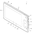
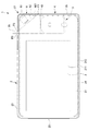
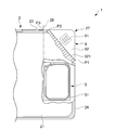
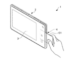
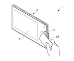
以下、本発明の実施形態について、図面を参照しながら説明する。図1は、本発明の電子機器の一実施形態としての携帯電子機器を示す斜視図である。図2は、図1の携帯電子機器1の正面図である。図3は、図2の携帯電子機器1の平面図である。図4は、図2の携帯電子機器1の右側面図である。図5は、図2の携帯電子機器1の要部を断面にして示す図である。図6は、図2の携帯電子機器1の別の要部を断面にして示す図である。図7は、接触型ICカードの決済機能を実行する様子を示す図である。図8は、非接触型ICカードの決済機能を実行する様子を示す図である。図9は、磁気カードの決済機能を実行する様子を示す図である。
Hereinafter, embodiments of the present invention will be described with reference to the drawings. FIG. 1 is a perspective view showing a portable electronic device as an embodiment of the electronic device of the present invention. FIG. 2 is a front view of the portable
図1〜図4に示すように、この携帯電子機器1は、筐体2と、タッチパネル・表示部3と、接触型IC読み取り部4と、非接触型IC読み取り部5と、磁気読み取り部6とを備える。携帯電子機器1は、タブレット型端末として一般的な機能、例えば、通話機能、データ通信機能、インターネット接続機能、位置情報(GPS)機能、等を備えてもよい。
As shown in FIGS. 1 to 4, the portable
筐体2は、携帯電子機器1の外側形状を画定するものであり、扁平な板状の略直方体形状を有する。筐体2は、前面視において略長方形を呈する横長の前面21及び背面22と、上方の横向き側面(上横側面、第2の側面)23と、下方の横向き側面(下横側面)24と、左方の縦向き側面(左縦側面)25と、右方の縦向き側面(右縦側面、第1の側面)26とを備える。なお、本明細書において「略長方形」とは、全体として長方形とみなせる形状を全て含み、例えば、完全な長方形、角隅部が丸みを帯びた長方形、辺の部分が少し湾曲した形状なども含む。
The
筐体2の前面21は、略矩形の透明な表示領域211と、表示領域211の周囲を取り囲む不透明な枠状領域212とを備える。筐体2の前面21は、ガラスやプラスチックのような材料で構成される。筐体2の背面22は、例えばアルミニウム合金やマグネシウム合金のような金属材料で構成される。筐体2の横側面23、24、及び縦側面25、26は、例えばアルミニウム合金やマグネシウム合金のような金属材料で構成されるか、又は高剛性樹脂で構成される。高剛性樹脂とは、例えば、ガラス繊維、カーボン繊維、その他の強化繊維及びタルクのような添加剤を樹脂中に混入した繊維強化樹脂である。
The
タッチパネル・表示部3は、筐体2の前面21の表示領域211に設けられる。タッチパネル・表示部3は、タッチパネルと表示部とを備える。タッチパネルは、接触式の入力機能を有する圧電式又は静電式のものである。
The touch panel /
図5に示すように、接触型IC読み取り部4は、接触型ICセンサ41と、接触型ICカード用挿入溝42とを備える。図7に示すように、接触型ICセンサ41は、接触型ICカードC1のICチップに接触して、ICチップから電子情報を取得する。接触型ICカード用挿入溝42は、接触型ICカードC1のICチップを接触型ICセンサ41の位置に誘導するために筐体2内に設けられる。
As shown in FIG. 5, the contact
接触型ICカード用挿入溝42は、筐体2の右縦側面26に開口した凹溝である。接触型ICセンサ41の配置並びに接触型ICカード用挿入溝42の配置及び深さは、接触型ICカードC1を停止する位置まで接触型ICカード用挿入溝42に挿入したとき、接触型ICカードC1のICチップが接触型ICセンサ41の所定の接触位置に静止するように設定されている。
The contact type IC
図2、図4に示すように、接触型ICカード用挿入溝42は、筐体2の右縦側面26の上下方向の中央部分よりもやや下方に配置される。また、筐体2の右縦側面26の左右方向(筐体2の厚み方向)に関しては、接触型ICカード用挿入溝42は、筐体2の背面22に近い側に配置される。
As shown in FIGS. 2 and 4, the contact IC
すなわち、接触型IC読み取り部4は、筐体2の右縦側面26に隣接して、上下方向の中央部分よりもやや下方において、筐体2の厚み方向に関して背面22に近い側に配置される。
That is, the contact-type
図6に示すように、非接触型IC読み取り部5は、アンテナを有する非接触型ICセンサ51を備える。非接触型ICカードC2は、ICチップとアンテナとを備える。図8に示すように、非接触型ICセンサ51のアンテナと非接触型ICカードC2のアンテナとが接近して両者間でデータを送受信することにより、非接触型IC読み取り部5は、非接触型ICカードC2のICチップから電子情報を取得する。非接触型ICカードC2の例としては、NFC(Near Field Communication)規格のカードが挙げられる。
As shown in FIG. 6, the non-contact type
図2、図4に示すように、非接触型IC読み取り部5は、筐体2の右縦側面26に隣接して、上下方向の中央部分よりもやや下方において、筐体2の厚み方向に関して前面21に近い側に配置される。そのため、非接触型ICカードC2を筐体2の前面21において非接触型IC読み取り部5に近接させることにより、非接触型ICカードC2のICチップの電子情報は、非接触型ICセンサ51により取得される。
As shown in FIGS. 2 and 4, the non-contact type
すなわち、筐体2の厚み方向に関して前面21に近い側に配置される非接触型IC読み取り部5と、筐体2の厚み方向に関して背面22に近い側に配置される接触型IC読み取り部4とは、筐体2の前面視において大部分(例えば70%以上)が重なり合うように配置される。そのため、接触型IC読み取り部4及び非接触型IC読み取り部5が配置される領域には、磁気読み取り部6を配置する余裕スペースが無い。
That is, the non-contact type
図6に示すように、磁気読み取り部6は、磁気センサ61と、磁気カード用挿入溝62とを備える。磁気センサ61は、磁気ヘッドとも呼ばれるもので、図9に示すように、磁気カードC3の磁気記録部C31から磁気情報を取得する。磁気カード用挿入溝62は、磁気カードC3の磁気記録部C31を磁気センサ61が走査するために筐体2に設けられる。
As shown in FIG. 6, the
図2に示すように、磁気読み取り部6は、接触型IC読み取り部4及び非接触型IC読み取り部5と同様に、筐体2の右縦側面26に隣接して配置される。ただし、接触型IC読み取り部4及び非接触型IC読み取り部5が筐体2の前面視において重なり合って配置されている領域には配置する余裕スペースが無いので、その領域よりも上にある上方領域と下にある下方領域とを比較して、高さがより大きい上方領域に、磁気読み取り部6は、配置される。
As shown in FIG. 2, the
磁気カード用挿入溝62は、筐体2の右縦側面26と上横側面23とが交わる角隅部27において、上横側面23上の所定の第2の位置P2から、接触型IC読み取り部4及び非接触型IC読み取り部5に近接する右縦側面26上の所定の第1の位置P1まで直線状に延びる底面621を有する。すなわち、磁気カード用挿入溝62は、底面621を斜辺とする略三角形状の凹溝であり、残りの2辺は上横側面23及び右縦側面26に開口している。なお、筐体2の前面視において接触型IC読み取り部4及び非接触型IC読み取り部5から第1の位置P1までの距離は、例えば、10mm以内である。
The magnetic
図3、図4に示すように、筐体2の厚み方向に関しては、磁気カード用挿入溝62は、筐体2の前面21に近い側に配置される。そのため、磁気カード用挿入溝62の底面621の右縦側面26上の第1の位置P1は、接触型IC読み取り部4に近接する位置ではなく、非接触型IC読み取り部5に近接する位置である。
As shown in FIGS. 3 and 4, the magnetic
磁気カード用挿入溝62の底面621の上横側面23上の第2の位置P2は、接触型IC読み取り部4及び非接触型IC読み取り部5の右縦側面26とは反対側の部位を通り且つ右縦側面26と平行に延びる仮想線28が上横側面23と交差する位置P3よりも、角隅部27の側に配置される。この場合には、仮想線28が通る部位は、非接触型IC読み取り部5の右縦側面26から最も離間した部位である。
The second position P2 on the upper
次に、上記のように構成された携帯電子機器1の作用について、順に説明する。
図7に示すように、接触型ICカードC1を手に持って接触型IC読み取り部4の接触型ICカード用挿入溝42に停止位置まで挿入すると、接触型ICカードC1のICチップが接触型ICセンサ41の所定の接触位置に静止する。そのため、接触型ICセンサ41は、接触型ICカードC1のICチップから電子情報を取得する。これにより、携帯電子機器1は、接触型ICカードC1の決済機能を実行する。
Next, the operation of the mobile
As shown in FIG. 7, when the contact IC card C1 is held in the hand and inserted into the contact IC
図8に示すように、非接触型ICカードC2を手に持って筐体2の前面21において非接触型IC読み取り部5の非接触型ICセンサ51に接近させると、非接触型IC読み取り部5は、非接触型ICカードC2のICチップから電子情報を取得する。これにより、携帯電子機器1は、非接触型ICカードC2の決済機能を実行する。
As shown in FIG. 8, when the non-contact IC card C <b> 2 is held in the hand and brought close to the
図9に示すように、磁気カードC3を手に持って磁気読み取り部6の磁気カード用挿入溝62に上横側面23側から挿入して、底面621に沿って右縦側面26側まで通過させると、磁気センサ61は、磁気カードC3の磁気記録部C31から磁気情報を取得する。これにより、携帯電子機器1は、磁気カードC3の決済機能を実行する。
As shown in FIG. 9, the user holds the magnetic card C <b> 3 in the hand and inserts it into the magnetic
実施形態の携帯電子機器1によれば、例えば以下の効果が奏される。
実施形態の携帯電子機器1は、筐体2と、接触型IC読み取り部4と、非接触型IC読み取り部5と、磁気読み取り部6とを備える。そのため、接触型ICカードC1、非接触型ICカードC2、磁気カードC3の全ての決済機能を1台の携帯電子機器1で実行することができる。
According to the portable
The portable
接触型IC読み取り部4、非接触型IC読み取り部5、及び磁気読み取り部6は、全て筐体2の右縦側面26に隣接して配置される。
そのため、例えば、接触型IC読み取り部4、非接触型IC読み取り部5、及び磁気読み取り部6が筐体2の各所にバラバラに配置される場合に比べて、接触型IC読み取り部4、非接触型IC読み取り部5、及び磁気読み取り部6の配置領域を全体としてコンパクトに纏めることができ、その結果、携帯電子機器1をよりコンパクトに構成することができる。
The contact type
Therefore, for example, compared with the case where the contact
限られた領域に磁気読み取り部6を配置するため、磁気カード用挿入溝62は、筐体2の右縦側面26と上横側面23とが交わる角隅部27において、上横側面23上の所定の第2の位置P2から右縦側面26上の所定の第1の位置P1まで直線状に延びる底面621を有する。すなわち、磁気カード用挿入溝62は、底面621を斜辺とする略三角形状の凹溝であり、残りの2辺は上横側面23及び右縦側面26に開口している。
そのため、第1の側面である右縦側面26に沿う方向の磁気読み取り部6と接触型IC読み取り部4及び非接触型IC読み取り部5との配置領域を小さくすることができ、カードの決済機能を有するコンパクトな電子機器を実現することができる。また、磁気カード用挿入溝62が筐体2の右縦側面26に平行な底面を有する場合に比べて、底面621の長さをより長く確保することができ、磁気カードC3の読み取り精度をそれだけ向上させることができる。
In order to arrange the
Therefore, the arrangement area of the
磁気カード用挿入溝62の底面621の上横側面23上の第2の位置P2は、接触型IC読み取り部4及び非接触型IC読み取り部5の右縦側面26とは反対側の部位を通って右縦側面26と平行に延びる仮想線28が上横側面23と交差する位置P3よりも、角隅部27の側に配置される。すなわち、磁気カード用挿入溝62の底面621は、仮想線28よりも右縦側面26の側の領域に収まる。
そのため、接触型IC読み取り部4、非接触型IC読み取り部5、及び磁気読み取り部6の配置領域全体のコンパクト化に寄与することができる。
The second position P2 on the upper
Therefore, it is possible to contribute to downsizing of the entire arrangement region of the contact type
筐体2の右縦側面26に隣接して、筐体2の厚み方向に関して背面22に近い側に接触型IC読み取り部4が配置され、前面21に近い側に非接触型IC読み取り部5が配置され、しかも、接触型IC読み取り部4と非接触型IC読み取り部5とは、筐体2の前面視において大部分が重なり合うように配置される。
そのため、接触型IC読み取り部4及び非接触型IC読み取り部5の前面視の配置領域を大幅にコンパクトに纏めることができて、携帯電子機器1をよりコンパクトに構成することができる。
Adjacent to the right
Therefore, the arrangement area of the front view of the contact type
接触型IC読み取り部4及び非接触型IC読み取り部5の配置領域にさらに、磁気読み取り部6を筐体2の前面視において重なり合うように配置することは、携帯電子機器1の薄さを増大させることに繋がるので、避けなければならない。そこで、実施形態においては、筐体2の右縦側面26に隣接して、接触型IC読み取り部4及び非接触型IC読み取り部5の配置領域よりも上にある上方領域と下にある下方領域とを比較して、高さがより大きい上方領域に、磁気読み取り部6は配置される。
そのため、接触型IC読み取り部4、非接触型IC読み取り部5、及び磁気読み取り部6の配置領域全体のコンパクト化に寄与することができる。
Arranging the
Therefore, it is possible to contribute to downsizing of the entire arrangement region of the contact type
以上、本発明の好適な実施形態について説明したが、本発明は、前述した実施形態に限定されることなく、種々の形態で実施することができる。
例えば、実施形態では、接触型IC読み取り部4と非接触型IC読み取り部5とを、筐体2の前面視において大部分が重なり合うように配置したが、本発明はこれに制限されない。例えば、接触型IC読み取り部4と非接触型IC読み取り部5とを、筐体2の前面視において重ならないように配置してもよい。
As mentioned above, although preferred embodiment of this invention was described, this invention can be implemented with a various form, without being limited to embodiment mentioned above.
For example, in the embodiment, the contact-type
また、携帯電子機器1の厚みを極限まで薄くするなど、必要に応じて、接触型IC読み取り部4又は非接触型IC読み取り部5のいずれか一方を省略して、接触型IC読み取り部4及び磁気読み取り部6のみを備えた携帯電子機器1、又は、非接触型IC読み取り部5及び磁気読み取り部6のみを備えた携帯電子機器1を構成してもよい。
接触型IC読み取り部4と非接触型IC読み取り部5は、筐体2の長手方向に沿う側面の側に配置されていてもよい。タッチパネル及び/又は表示部は設けられていなくてもよい。
Further, if necessary, one of the contact
The contact-type
実施形態の筐体2は、前面視において略長方形で板状であるが、この形状に制限されず、その他の前面視形状や厚み方向形状であってもよい。
実施形態は携帯電子機器であるが、本発明はこれに制限されない。例えば、電源コードを備えてそのコードの延びる範囲でどこにでも置けるように構成された小型の載置式の決済電子機器などに本発明を適用してもよい。つまり、本発明は、携帯型ではない電子機器であってもよい。
The
The embodiment is a portable electronic device, but the present invention is not limited to this. For example, the present invention may be applied to a small mounting-type payment electronic device that includes a power cord and is configured to be placed anywhere within the extension range of the cord. That is, the present invention may be a non-portable electronic device.
1 携帯電子機器(電子機器)
2 筐体
3 タッチパネル・表示部
4 接触型IC読み取り部
5 非接触型IC読み取り部
6 磁気読み取り部
21 前面
23 上横側面(第2の側面)
26 右縦側面(第1の側面)
27 角隅部
28 仮想線
61 磁気センサ
62 磁気カード用挿入溝
621 底面
C1 接触型ICカード
C2 非接触型ICカード
C3 磁気カード
C31 磁気記録部
P1 第1の位置
P2 第2の位置
P3 交差する位置
1 Portable electronic devices (electronic devices)
2
26 Right vertical side (first side)
27
Claims (4)
前記筐体と一体的に構成され、決済に係る接触型ICカードの読み取り処理を行う接触型IC読み取り部、及び/又は、非接触型ICカードの読み取り処理を行う非接触型IC読み取り部と、
前記筐体と一体的に構成され、決済に係る磁気カードの読み取り処理を行う磁気読み取り部と、を備える電子機器であって、
前記接触型IC読み取り部及び/又は非接触型IC読み取り部は、前記筐体の前記第1の側面の側に配置され、
前記磁気読み取り部は、磁気カードの磁気記録部から磁気情報を取得する磁気センサと、磁気カードの磁気記録部を前記磁気センサが走査するために前記筐体に設けられる磁気カード用挿入溝と、を備え、
前記磁気カード用挿入溝は、前記角隅部において前記第2の側面上の第2の位置から前記第1の側面上の第1の位置まで直線状に延びる底面を有する、電子機器。 A housing having a first side surface, a second side surface adjacent to the first side surface, and a corner portion where these side surfaces intersect;
A contact type IC reading unit configured to be integrated with the housing and performing a reading process of a contact type IC card related to payment; and / or a non-contact type IC reading unit performing a reading process of a non-contact type IC card;
A magnetic reading unit configured integrally with the housing and performing a reading process of a magnetic card related to payment,
The contact-type IC reading unit and / or the non-contact-type IC reading unit is disposed on the first side surface side of the housing,
The magnetic reading unit includes a magnetic sensor for acquiring magnetic information from the magnetic recording unit of the magnetic card, and a magnetic card insertion groove provided in the housing for the magnetic sensor to scan the magnetic recording unit of the magnetic card; With
The magnetic card insertion groove has a bottom surface that linearly extends from a second position on the second side surface to a first position on the first side surface at the corner portion.
Priority Applications (3)
| Application Number | Priority Date | Filing Date | Title |
|---|---|---|---|
| JP2016125844A JP6042017B1 (en) | 2016-06-24 | 2016-06-24 | Electronics |
| PCT/JP2016/070248 WO2017221431A1 (en) | 2016-06-24 | 2016-07-08 | Electronic device |
| TW105121735A TW201800982A (en) | 2016-06-24 | 2016-07-11 | Electronic device |
Applications Claiming Priority (1)
| Application Number | Priority Date | Filing Date | Title |
|---|---|---|---|
| JP2016125844A JP6042017B1 (en) | 2016-06-24 | 2016-06-24 | Electronics |
Publications (2)
| Publication Number | Publication Date |
|---|---|
| JP6042017B1 true JP6042017B1 (en) | 2016-12-14 |
| JP2017228237A JP2017228237A (en) | 2017-12-28 |
Family
ID=57543873
Family Applications (1)
| Application Number | Title | Priority Date | Filing Date |
|---|---|---|---|
| JP2016125844A Expired - Fee Related JP6042017B1 (en) | 2016-06-24 | 2016-06-24 | Electronics |
Country Status (3)
| Country | Link |
|---|---|
| JP (1) | JP6042017B1 (en) |
| TW (1) | TW201800982A (en) |
| WO (1) | WO2017221431A1 (en) |
Citations (3)
| Publication number | Priority date | Publication date | Assignee | Title |
|---|---|---|---|---|
| JP2003272051A (en) * | 2002-03-19 | 2003-09-26 | Toshiba Tec Corp | Self checkout device |
| JP2013541105A (en) * | 2010-10-13 | 2013-11-07 | スクエア インコーポレイテッド | System and method for financial transactions through a miniaturized card reader with decryption on a seller's mobile device |
| JP2015028741A (en) * | 2013-07-31 | 2015-02-12 | 佳弘 東 | Portable electronic device |
-
2016
- 2016-06-24 JP JP2016125844A patent/JP6042017B1/en not_active Expired - Fee Related
- 2016-07-08 WO PCT/JP2016/070248 patent/WO2017221431A1/en not_active Ceased
- 2016-07-11 TW TW105121735A patent/TW201800982A/en unknown
Patent Citations (3)
| Publication number | Priority date | Publication date | Assignee | Title |
|---|---|---|---|---|
| JP2003272051A (en) * | 2002-03-19 | 2003-09-26 | Toshiba Tec Corp | Self checkout device |
| JP2013541105A (en) * | 2010-10-13 | 2013-11-07 | スクエア インコーポレイテッド | System and method for financial transactions through a miniaturized card reader with decryption on a seller's mobile device |
| JP2015028741A (en) * | 2013-07-31 | 2015-02-12 | 佳弘 東 | Portable electronic device |
Non-Patent Citations (1)
| Title |
|---|
| JPN6016038795; 'クレジット(磁気/IC)、銀聯、電子マネー、NFC対応のスマホ決済リーダを開発(ロイヤルゲート)' [online] , 20120509 * |
Also Published As
| Publication number | Publication date |
|---|---|
| WO2017221431A1 (en) | 2017-12-28 |
| TW201800982A (en) | 2018-01-01 |
| JP2017228237A (en) | 2017-12-28 |
Similar Documents
| Publication | Publication Date | Title |
|---|---|---|
| JP5639236B1 (en) | Portable electronic devices | |
| JP6042017B1 (en) | Electronics | |
| CN206961267U (en) | The integral type POS | |
| JP7482468B1 (en) | Portable payment terminal | |
| JP6144721B2 (en) | Portable electronic devices | |
| JP2017228090A (en) | Electronics | |
| JP2015146220A (en) | Portable electronic apparatus | |
| JP2025111889A (en) | Information processing device | |
| JP2015043241A (en) | Portable electronic devices | |
| CN205881015U (en) | Multi -functional transaction terminal based on campus card | |
| JP2015032322A (en) | Portable electronic devices | |
| BR122016003864A2 (en) | portable electronic device |
Legal Events
| Date | Code | Title | Description |
|---|---|---|---|
| TRDD | Decision of grant or rejection written | ||
| A01 | Written decision to grant a patent or to grant a registration (utility model) |
Free format text: JAPANESE INTERMEDIATE CODE: A01 Effective date: 20161011 |
|
| A61 | First payment of annual fees (during grant procedure) |
Free format text: JAPANESE INTERMEDIATE CODE: A61 Effective date: 20161108 |
|
| R150 | Certificate of patent or registration of utility model |
Ref document number: 6042017 Country of ref document: JP Free format text: JAPANESE INTERMEDIATE CODE: R150 |
|
| R250 | Receipt of annual fees |
Free format text: JAPANESE INTERMEDIATE CODE: R250 |
|
| R250 | Receipt of annual fees |
Free format text: JAPANESE INTERMEDIATE CODE: R250 |
|
| RD03 | Notification of appointment of power of attorney |
Free format text: JAPANESE INTERMEDIATE CODE: R3D03 |
|
| R250 | Receipt of annual fees |
Free format text: JAPANESE INTERMEDIATE CODE: R250 |
|
| R250 | Receipt of annual fees |
Free format text: JAPANESE INTERMEDIATE CODE: R250 |
|
| R250 | Receipt of annual fees |
Free format text: JAPANESE INTERMEDIATE CODE: R250 |
|
| LAPS | Cancellation because of no payment of annual fees |