JP6058024B2 - Railway wheels - Google Patents
Railway wheels Download PDFInfo
- Publication number
- JP6058024B2 JP6058024B2 JP2014547138A JP2014547138A JP6058024B2 JP 6058024 B2 JP6058024 B2 JP 6058024B2 JP 2014547138 A JP2014547138 A JP 2014547138A JP 2014547138 A JP2014547138 A JP 2014547138A JP 6058024 B2 JP6058024 B2 JP 6058024B2
- Authority
- JP
- Japan
- Prior art keywords
- web
- point
- radius curve
- rim
- curve
- Prior art date
- Legal status (The legal status is an assumption and is not a legal conclusion. Google has not performed a legal analysis and makes no representation as to the accuracy of the status listed.)
- Expired - Fee Related
Links
- 238000004826 seaming Methods 0.000 claims 2
- 238000013461 design Methods 0.000 description 27
- DOSMHBDKKKMIEF-UHFFFAOYSA-N 2-[3-(diethylamino)-6-diethylazaniumylidenexanthen-9-yl]-5-[3-[3-[4-(1-methylindol-3-yl)-2,5-dioxopyrrol-3-yl]indol-1-yl]propylsulfamoyl]benzenesulfonate Chemical compound C1=CC(=[N+](CC)CC)C=C2OC3=CC(N(CC)CC)=CC=C3C(C=3C(=CC(=CC=3)S(=O)(=O)NCCCN3C4=CC=CC=C4C(C=4C(NC(=O)C=4C=4C5=CC=CC=C5N(C)C=4)=O)=C3)S([O-])(=O)=O)=C21 DOSMHBDKKKMIEF-UHFFFAOYSA-N 0.000 description 8
- 238000010835 comparative analysis Methods 0.000 description 5
- 230000000930 thermomechanical effect Effects 0.000 description 4
- 238000004458 analytical method Methods 0.000 description 3
- 238000011160 research Methods 0.000 description 3
- 230000008901 benefit Effects 0.000 description 2
- 230000000694 effects Effects 0.000 description 2
- 238000005516 engineering process Methods 0.000 description 2
- 230000003137 locomotive effect Effects 0.000 description 2
- 238000000034 method Methods 0.000 description 2
- 229910000831 Steel Inorganic materials 0.000 description 1
- 230000009471 action Effects 0.000 description 1
- 230000002411 adverse Effects 0.000 description 1
- 238000004364 calculation method Methods 0.000 description 1
- 238000005266 casting Methods 0.000 description 1
- 230000008859 change Effects 0.000 description 1
- 238000005094 computer simulation Methods 0.000 description 1
- 238000001816 cooling Methods 0.000 description 1
- 238000001514 detection method Methods 0.000 description 1
- 238000010586 diagram Methods 0.000 description 1
- 238000005242 forging Methods 0.000 description 1
- 238000010438 heat treatment Methods 0.000 description 1
- 230000006872 improvement Effects 0.000 description 1
- 238000007689 inspection Methods 0.000 description 1
- 238000004519 manufacturing process Methods 0.000 description 1
- 230000008569 process Effects 0.000 description 1
- 238000005096 rolling process Methods 0.000 description 1
- 239000010959 steel Substances 0.000 description 1
- 238000012360 testing method Methods 0.000 description 1
- 230000007704 transition Effects 0.000 description 1
Images


Classifications
-
- B—PERFORMING OPERATIONS; TRANSPORTING
- B60—VEHICLES IN GENERAL
- B60B—VEHICLE WHEELS; CASTORS; AXLES FOR WHEELS OR CASTORS; INCREASING WHEEL ADHESION
- B60B17/00—Wheels characterised by rail-engaging elements
- B60B17/0006—Construction of wheel bodies, e.g. disc wheels
-
- B—PERFORMING OPERATIONS; TRANSPORTING
- B60—VEHICLES IN GENERAL
- B60B—VEHICLE WHEELS; CASTORS; AXLES FOR WHEELS OR CASTORS; INCREASING WHEEL ADHESION
- B60B17/00—Wheels characterised by rail-engaging elements
- B60B17/0055—Wheels characterised by rail-engaging elements with non-elastic tyres (e.g. of particular profile or composition)
-
- B—PERFORMING OPERATIONS; TRANSPORTING
- B60—VEHICLES IN GENERAL
- B60B—VEHICLE WHEELS; CASTORS; AXLES FOR WHEELS OR CASTORS; INCREASING WHEEL ADHESION
- B60B2900/00—Purpose of invention
- B60B2900/10—Reduction of
- B60B2900/111—Weight
-
- B—PERFORMING OPERATIONS; TRANSPORTING
- B60—VEHICLES IN GENERAL
- B60B—VEHICLE WHEELS; CASTORS; AXLES FOR WHEELS OR CASTORS; INCREASING WHEEL ADHESION
- B60B2900/00—Purpose of invention
- B60B2900/30—Increase in
- B60B2900/311—Rigidity or stiffness
-
- Y—GENERAL TAGGING OF NEW TECHNOLOGICAL DEVELOPMENTS; GENERAL TAGGING OF CROSS-SECTIONAL TECHNOLOGIES SPANNING OVER SEVERAL SECTIONS OF THE IPC; TECHNICAL SUBJECTS COVERED BY FORMER USPC CROSS-REFERENCE ART COLLECTIONS [XRACs] AND DIGESTS
- Y02—TECHNOLOGIES OR APPLICATIONS FOR MITIGATION OR ADAPTATION AGAINST CLIMATE CHANGE
- Y02T—CLIMATE CHANGE MITIGATION TECHNOLOGIES RELATED TO TRANSPORTATION
- Y02T10/00—Road transport of goods or passengers
- Y02T10/80—Technologies aiming to reduce greenhouse gasses emissions common to all road transportation technologies
- Y02T10/86—Optimisation of rolling resistance, e.g. weight reduction
Landscapes
- Engineering & Computer Science (AREA)
- Mechanical Engineering (AREA)
- Braking Arrangements (AREA)
- Tires In General (AREA)
- Rolling Contact Bearings (AREA)
Description
本発明は、輸送技術、特に鉄道車輪の設計に関するものである。 The present invention relates to transportation technology, and more particularly to the design of railway wheels.
さまざまな国で使用される鉄道車輪は、車両の運転条件、車両及び機関車のデザイン、並びに、輪軸(ホイールセット)の製造及び鉄道輸送におけるそれらの運転で開発されたある種の伝統に関連したデザインの違いがある。それと同時に、車輪は、いずれの場合も3つの主要部分、リム、ハブ、及びウェブから構成される。 Railway wheels used in different countries are related to vehicle operating conditions, vehicle and locomotive designs, and certain traditions developed in wheelset manufacturing and their operation in rail transport. There is a difference in design. At the same time, the wheel is in each case composed of three main parts, a rim, a hub and a web.
ホイールウェブの形状の選択は、重量、剛性、及び耐荷重などの車輪基本性能特性を提供するための最も重要な課題である。 The choice of wheel web shape is the most important challenge to provide basic wheel performance characteristics such as weight, stiffness and load bearing.
異なるデザインのウェブを有する車輪が世界的な実施で知られており、このデザインは、多くの場合、サイズ及びハブに対するリムの相互位置によって決まる。この発明は、ヨーロッパの鉄道システムでの使用を目的とし、ヨーロッパの鉄道システムで最も広く使用されているのは、接線方向のウェブ形状を有する標準的な車輪、いわゆるOREホイールであり、この車輪は、ホイールセットの車軸あたり22.5重量トン(tnf)までの荷重に使用される。この車輪のデザインは、ブレーキシューに対する車輪の摩擦に起因する熱負荷、及び線路の曲線部を走るときに車輪に作用する機械的負荷の下で、高レベルのストレスを有する。また、OREホイールの重大な欠点は、その高重量である。 Wheels with different designs of webs are known in global practice, and this design often depends on the size and mutual position of the rim relative to the hub. The present invention is intended for use in European railway systems, and the most widely used in European railway systems is a standard wheel with a tangential web shape, the so-called ORE wheel, Used for loads up to 22.5 tonnes (tnf) per wheelset axle. This wheel design has a high level of stress under the thermal load caused by the wheel friction against the brake shoe and the mechanical load acting on the wheel when running on the curved part of the track. Also, a significant drawback of the ORE wheel is its high weight.
特許文献1による鉄道車輪のデザインは、中央線がコサイン関数によって決められたベル型ウェブで知られており、このデザインは、ホイールセットの車軸あたり23.5重量トン(tnf)までの最大負荷で、ヨーロッパの鉄道において広く受け入れられた。このデザインは、すべての既知の類似物の中で最小の重量を有する。しかしながら、この車輪のデザインをより大きな車軸荷重に使用するために、ウェブの厚さ及びハブの壁の増大が必要とされ、これにより車輪の軽量の利点が失われる。 The design of a railway wheel according to US Pat. No. 6,057,089 is known for a bell-shaped web whose center line is determined by a cosine function, which is designed for maximum loads up to 23.5 tonnes (tnf) per wheelset axle. Widely accepted in European railways. This design has the lowest weight among all known analogues. However, in order to use this wheel design for larger axle loads, an increase in web thickness and hub wall is required, thereby losing the light weight advantage of the wheel.
この課題の1つの解決策の変形形態が、本発明の原型とみなされる特許文献2に記載されており、その発明では、ホイールウェブの横断方向の形状は、3つの特徴点を通る理論中央線の周りに配置され、一方、ウェブをハブと継ぎ合わせる場所に示された第1の点と、ウェブをリムと継ぎ合わせる場所に示された第2の点とは、ホイール回転軸に垂直であり且つ中央平面からホイールリムの外面に向かってずらされた、同一平面に配置される。前記平面とホイールウェブの理論中央線の示された中心点との間の距離は、ホイールリム幅の最大0.5である。このデザインの利点は、機械的負荷に起因する応力のレベルが高いハブを継ぎ合わせる領域でウェブの厚さを増加することができることであるが、この構造体の重量及び熱負荷による応力のレベルは、特許文献1による車輪と比べると大幅に増大する。このデザインの車輪は広く使用されていない。 A variant of one solution to this problem is described in US Pat. No. 6,057,089, which is considered the prototype of the present invention, in which the wheel web cross-sectional shape is a theoretical centerline passing through three feature points. While the first point shown where the web is spliced with the hub and the second point shown where the web is spliced with the rim is perpendicular to the wheel rotation axis And it arrange | positions in the same plane shifted toward the outer surface of the wheel rim from the center plane. The distance between the plane and the indicated center point of the theoretical center line of the wheel web is a maximum of 0.5 of the wheel rim width. The advantage of this design is that the thickness of the web can be increased in the area where the hubs with high levels of stress due to mechanical loading are joined, but the level of stress due to the weight of the structure and the thermal load is Compared with the wheel by patent document 1, it increases significantly. This design wheel is not widely used.
本発明の技術的結果は、鉄道車輪の性能特性の改善、すなわち、
運転荷重の作用によるホイールの低ストレス状態と、
すべての既知の類似物の中で最小の構造重量を保証しつつ、車軸あたり23.5重量トン(tnf)より大きい最大荷重での使用が可能性であることと、
ブレーキシュー対する摩擦の過程での加熱及びその後の冷却時のホイールリムの横方向の少ない変形度と
をもたらすことができるホイールウェブの最適な形状を選択することを目的とする。
The technical result of the present invention is the improvement of the performance characteristics of railway wheels, i.e.
Low stress state of the wheel due to the action of driving load,
The possibility of use at maximum loads greater than 23.5 tonnes (tnf) per axle, while guaranteeing the smallest structural weight among all known analogues;
The object is to select an optimal shape of the wheel web that can provide heating in the course of friction against the brake shoe and subsequent low degree of lateral deformation of the wheel rim during cooling.
この技術的結果は、車輪の回転軸に垂直な中央平面を有する鉄道車輪であって、トレッド面及びフランジによって形成されたリムを含み、且つハブと、外面及び内面によって形成されたウェブとを含み、ウェブは横断方向のウェブ形状の理論中央線が、ウェブをリムと継ぎ合わせる場所に位置する第1の点と、中心点と、ウェブをハブと継ぎ合わせる場所に位置する第2の点とを通過し、中心点において理論中央線が中央平面からフランジと反対方向に最大のずれを有するように作られ、ウェブの外面は、リム側が第1外側半径曲線によって、ハブ側が第1外側半径曲線の曲率と方向が一致する曲率を有する第2外側半径曲線によって形成され、前記曲線は、第1及び第2外側半径曲線の曲率の方向と反対の曲率を有するリム側の第3外側半径曲線及びハブ側の第4外側半径曲線によってウェブの中央部で互いに一致し、一方、ウェブの内面は、リム側が第1内側半径曲線によって、ハブ側が第1内側半径曲線の曲率の方向に一致する曲率を有する第1内側半径曲線によって形成され、前記曲線は、第1及び第2内側半径曲線の曲率の方向と反対の曲率を有するリム側の第3内側半径曲線及びハブ側の第4内側半径曲線によってウェブの中央部で互いに一致し、
外側ウェブ面のための第1及び第2外側半径曲線の半径はトレッド直径の0.04から0.05であり、第3外側半径曲線の半径はトレッド直径の0.08から0.1であり、第4外側半径曲線の半径はトレッド直径の0.07から0.09であり、内側ウェブ面のための第1内側半径曲線の半径はトレッド直径の0.08から0.1であり、第2及び第3内側半径曲線の半径はトレッド直径の0.06から0.08であり、第4内側半径曲線の半径はトレッド直径の0.04から0.06であり、第1の点は中央平面からフランジと反対の方向にリム幅の0.08以下の距離にずらされ、中心点は中央平面からリム幅の0.35から0.4の値の範囲内の距離にずらされ、第2の点は中央平面からフランジに向かってリム幅の0.1以下の距離にずらされ、一方、第2の点でのウェブ厚さに対する第1の点でのウェブ厚さの比は0.7から1.1であり、第2の点でのウェブ厚さに対する中心点でのウェブ厚さの比は0.7から0.9である鉄道車輪によって達成される。
The technical result is a railway wheel having a central plane perpendicular to the axis of rotation of the wheel, including a rim formed by a tread surface and a flange, and a hub and a web formed by the outer surface and the inner surface. The web has a theoretical centerline of the transverse web shape, a first point located where the web is joined to the rim, a center point, and a second point located where the web is joined to the hub. And the theoretical center line at the center point is made to have the greatest deviation from the center plane in the opposite direction of the flange, and the outer surface of the web has a first outer radius curve on the rim side and a first outer radius curve on the hub side. Formed by a second outer radius curve having a curvature whose direction coincides with the curvature, the curve being a third outer half on the rim side having a curvature opposite to the direction of curvature of the first and second outer radius curves. The center of the web coincides with the curve and the fourth outer radius curve on the hub side, while the inner surface of the web coincides with the direction of curvature of the first inner radius curve on the rim side and the first inner radius curve on the hub side. Formed by a first inner radius curve having a curvature, wherein the curve has a third inner radius curve on the rim side and a fourth inner radius on the hub side having a curvature opposite to the direction of curvature of the first and second inner radius curves. In the middle of the web by the curve,
The radius of the first and second outer radius curves for the outer web surface is 0.04 to 0.05 of the tread diameter, and the radius of the third outer radius curve is 0.08 to 0.1 of the tread diameter. The radius of the fourth outer radius curve is 0.07 to 0.09 of the tread diameter, the radius of the first inner radius curve for the inner web surface is 0.08 to 0.1 of the tread diameter, The radius of the second and third inner radius curves is 0.06 to 0.08 of the tread diameter, the radius of the fourth inner radius curve is 0.04 to 0.06 of the tread diameter, the first point is the center The center point is shifted from the plane in the opposite direction to the flange by a distance of 0.08 or less of the rim width, and the center point is shifted from the center plane by a distance within the range of 0.35 to 0.4 of the rim width. The point of rim width is 0.1 or less from the center plane toward the flange While the ratio of the web thickness at the first point to the web thickness at the second point is 0.7 to 1.1, centered on the web thickness at the second point The ratio of web thickness in points is achieved with railway wheels that are between 0.7 and 0.9.
シューブレーキの動作中、車輪は、リムを加熱して次いで冷却したときのリムの変形度に対する悪影響なしに、45分間55キロワットの熱負荷の繰り返しサイクルを吸収することができる。また、上記のウェブの構成と共に、0.7から1.1の範囲内にある第2の点でのウェブ厚さに対する第1の点でのウェブ厚さの比、及び、0.7から0.9の範囲内にある第2の点でのウェブ厚さに対する中心点でのウェブ厚さの比は、ウェブがリム及びハブと一致する場所にあるホイールの最も応力を受ける部分を強化することを可能にし、これにより、構造体の重量がすべての既知の類似物よりも5〜10%低い状態で車軸あたり23.5tnfを超える最大荷重で車輪を使用する可能性を提供する。 During shoe brake operation, the wheel can absorb a repeated cycle of 55 kilowatts of heat load for 45 minutes without adversely affecting the degree of rim deformation when the rim is heated and then cooled. In addition to the web configuration described above, the ratio of the web thickness at the first point to the web thickness at the second point in the range of 0.7 to 1.1, and 0.7 to 0 The ratio of the web thickness at the center point to the web thickness at the second point in the range of .9 strengthens the most stressed part of the wheel where the web coincides with the rim and hub. This provides the possibility of using wheels with a maximum load exceeding 23.5 tnf per axle with the structure weight 5-10% lower than all known analogues.
前記構成を有する車輪のウェブの外面及び内面を形成する曲線の半径、ウェブの理論中央線の特徴点の中央平面からのずれの間隔及び方向、並びに、これらの点での厚さの比に対して他の値を選択すると、各種運転負荷の作用下での車輪デザインの低ストレス状態、最小重量、及び熱負荷の下での満足できる横方向のリム変形度の最適な組み合わせを達成することができない。 The radius of the curve forming the outer and inner surfaces of the web of the wheel having the above configuration, the distance and direction of the deviation of the theoretical center line of the web from the center plane, and the thickness ratio at these points By selecting other values, it is possible to achieve the optimum combination of low stress state of the wheel design under the influence of various driving loads, minimum weight, and satisfactory lateral rim deformation under thermal loads. Can not.
本発明の本質は以下の図面により説明される。
図1に示される鉄道車輪は、車輪の回転軸Zに垂直な中央平面Pを有し、トレッド面2及びフランジ3によって形成されたリム1を含み、ハブ4と、外面6及び内面7によって形成されたウェブ5とを含み、ウェブ5は、ウェブの横断面形状の理論中央線8が、ウェブをリム1と継ぎ合わせる場所に位置する第1の点Aと、中心点Cと、ウェブ5をハブ4と継ぎ合わせる場所に位置する第2の点Bとを通るように設計され、中心点Cにおいて理論中央線8はフランジ3と反対方向に中央平面Pからの最大のずれを有する。ホイールウェブ5の特定の中央平面Pは、トレッド直径Dが測定される場所でホイールリム1を通過する。
The rail wheel shown in FIG. 1 has a central plane P perpendicular to the wheel axis of rotation Z and includes a rim 1 formed by a
ウェブ5の外面6は、リム1側が第1外側半径曲線R1によって、ハブ4側が第1外側半径曲線R1の曲率と方向が一致する曲率を有する第2外側半径曲線R2によって形成され、前記曲線は、第1外側半径曲線R1と第2外側半径曲線R2の曲率の方向とは反対の曲率を有するリム1側の第3外側半径曲線R3及びハブ4側の第4外側半径曲線R4によってウェブの中央部で互いに一致し、ウェブ5の内面7は、リム1側が第1内側半径曲線R5によって、ハブ4側が第1内側半径曲線R5の曲率の方向に一致する曲率を有する第2内側半径曲線R6によって形成され、前記曲線は、第1内側半径曲線R5及び第2内側半径曲線R6の曲率の方向とは反対の曲率を有するリム1側の第3内側半径曲線R7及びハブ4側の第4内側半径曲線R8によってウェブ5の中央部で互いに一致する。
The
第1の点Aは、中央平面Pからフランジ3と反対方向にリム幅Hの0.08以下の距離H1にずらされ、中心点Cは、中央平面Pからリム幅Hの0.35から0.4の距離H2にずらされ、第2の点Bは、中央平面Pからフランジ3に向かってリム幅Hの0.1以下の距離H3にずらされる。
The first point A is shifted from the center plane P in a direction opposite to the
第2の点Bにおけるウェブ5の厚さT2に対する第1の点Aにおけるウェブ5の厚さT1の比は、0.7から1.1であり、第2の点Bにおける厚さT2に対する中心点Cにおけるウェブ5の厚さT3の比は、0.7から0.9である。 The ratio of the thickness T1 of the web 5 at the first point A to the thickness T2 of the web 5 at the second point B is 0.7 to 1.1, and the center with respect to the thickness T2 at the second point B is The ratio of the thickness T3 of the web 5 at the point C is 0.7 to 0.9.
本発明によれば、車輪ウェブの最適な形状の選択は、主に運転において重大な機械的及び熱的負荷の作用からホイールの応力歪み状態を決定することを可能にする、UIC 510−5規格及びUIC B 169/RP 17レポートに記載された技術に従って、デザインの異なる変形形態の有限要素解析を使用して行われる。 According to the present invention, the selection of the optimal shape of the wheel web makes it possible to determine the stress-strain state of the wheel mainly from the effects of mechanical and thermal loads that are critical in operation, the UIC 510-5 standard. And according to the technique described in the UIC B 169 / RP 17 report, using finite element analysis of different variants of the design.
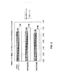
EN 13979−1の要件に従って行われた計算の結果、本発明のデザインは、図2に示されるように、同様の目的の車輪VAZ14/324及びVAZ18/319のデザインと比べて、それぞれ7kg及び19kgだけ少ない構造重量を提供する共に、良好なウェブの疲労強度特性を有する。 As a result of calculations performed in accordance with the requirements of EN 13979-1, the design of the present invention is 7 kg and 19 kg, respectively, as shown in FIG. 2, compared to the design of similar purpose wheels VAZ14 / 324 and VAZ18 / 319, respectively. It offers good web fatigue strength properties while providing as little structural weight as possible.
特許及び研究技術情報源の検索と本発明の類似物に関するデータを含む情報源の検出とを含めた、出願人によって行われた最新技術の分析は、出願人が本発明のすべての本質的な特徴と同じ特徴によって特徴付けられる類似物を発見しなかったことを示した。 State-of-the-art analysis performed by the applicant, including searching for patent and research technology information sources and detecting information sources that contain data relating to analogs of the invention. It was shown that no similarities characterized by the same features were found.
検出された類似物のリストの中から原型を決める過程で、特許請求の範囲に記載される本発明の鉄道車輪の本質的な特徴の組み合わせが、目的とする技術的結果に対して特定された。 In the process of determining the prototype from a list of detected analogues, the essential feature combinations of the claimed invention wheel are identified for the intended technical result. .
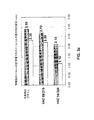
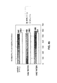
図3a、3b及び4a、4bに示すように、UIC B 169/RP 17に従って行われた、車輪へのブレーキ作動時のベンチテストのコンピュータシミュレーションの結果は、既存の類似物と同程度のリムの横方向の変形の程度とホイールの応力のレベルとによって本発明のデザインを特徴付ける。 As shown in FIGS. 3a, 3b and 4a, 4b, the results of a computer simulation of a bench test when braking to a wheel, performed according to UIC B 169 / RP 17, show that the rim is comparable to an existing analog. The design of the present invention is characterized by the degree of lateral deformation and the level of stress on the wheel.
出願人によって行われた特許及び科学研究文献の検索を含む従来技術の分析、及び本発明の類似物に関する情報を含む文献の検出は、本出願人が、本発明のすべての本質的な特徴に適合した(同一の)特徴によって定義される類似物を検出できなかったことを立証することを可能にする。 Prior art analysis, including search of patent and scientific research literature performed by the applicant, and detection of literature containing information on analogs of the present invention, enable the applicant to address all essential features of the present invention. It makes it possible to prove that an analogue defined by a matched (identical) feature could not be detected.
検出した類似物のリストからの原型の定義は、本発明の「鉄道車輪」において識別される技術的結果に関して不可欠であり且つ特許請求の範囲に記載される特徴の組合せの発見を可能にした。 The definition of the prototype from the list of detected analogs was essential with respect to the technical results identified in the “Railway Wheel” of the present invention and allowed the discovery of feature combinations as claimed.
検索結果は、請求項に係る発明が、出願人により決定された先行技術の専門家には明確に現れないことを示し、技術的結果の達成に対する請求項に係る発明の本質的な特徴によってもたらされる変化の影響は、何も検出されなかった。 The search results show that the claimed invention does not appear clearly to the prior art experts determined by the applicant and is brought about by the essential features of the claimed invention for the achievement of technical results. No change effects were detected.
提案された発明は、シューブレーキを使用する鉄道輸送設備車両のすべてのモデルに、特に車両及び機関車を先導する鉄道貨車に使用することができる。ホイールウェブのハブとリムへの遷移の場所にある、車輪の重要な領域における疲労強度の良好な不変性により、客車のように、シューブレーキの代わりにディスクブレーキが使用される鉄道輸送に本デザインを使用することも可能である。本発明によれば、車輪は、鉄道産業において使用される任意の品質の鋼から製造することができ、且つ、圧延、鍛造又は鋳造により周知の技術要件及び規格に従って製造することができる。 The proposed invention can be used in all models of rail transport equipment vehicles that use shoe brakes, particularly in rail freight cars that lead vehicles and locomotives. This design for rail transport where disc brakes are used instead of shoe brakes, like passenger cars, due to good invariance of fatigue strength in critical areas of the wheel at the transition to the hub and rim of the wheel web Can also be used. According to the invention, the wheels can be manufactured from any quality steel used in the railway industry and can be manufactured according to known technical requirements and standards by rolling, forging or casting.
特許請求の範囲に従うウェブの構成を有する鉄道車輪の理論的研究及び検査は、ヨーロッパの鉄道システム用の貨車に関して、すべての安全要件に準拠していること、及びホイールの性能の最適なレベルを提供できることを示した。このことは、出願人によって示された技術的結果の達成を証明する。 Theoretical research and inspection of railway wheels with a web configuration according to the claims provides compliance with all safety requirements and the optimum level of wheel performance for freight cars for European railway systems I showed that I can do it. This proves the achievement of the technical results shown by the applicant.
Claims (1)
前記ウェブの外面は、リム側が第1外側半径曲線によって、ハブ側が前記第1外側半径曲線の曲率と方向が一致する曲率を有する第2外側半径曲線によって形成され、前記第1及び第2外側半径曲線は、前記第1及び第2外側半径曲線の曲率に対して方向が反対の曲率を有するリム側の第3外側半径曲線及びハブ側の第4外側半径曲線によって前記ウェブの中央部で互いに一致し、
一方、前記ウェブの内面は、リム側が第1内側半径曲線によって、ハブ側が前記第1内側半径曲線の曲率と方向が一致する曲率を有する第2内側半径曲線によって形成され、前記第1及び第2内側半径曲線は、前記第1及び第2内側半径曲線の曲率に対して方向が反対の曲率を有するリム側の第3内側半径曲線及びハブ側の第4内側半径曲線によって前記ウェブの中央部で互いに一致し、
前記第1及び第2外側半径曲線の半径はトレッド直径の0.04から0.05であり、前記第3外側半径曲線の半径は前記トレッド直径の0.08から0.1であり、前記第4外側半径曲線の半径は前記トレッド直径の0.07から0.09であり、
前記第1内側半径曲線の半径は前記トレッド直径の0.08から0.1であり、前記第2及び第3内側半径曲線の半径は前記トレッド直径の0.06から0.08であり、前記第4内側半径曲線の半径は前記トレッド直径の0.04から0.06であり、
前記第1の点は前記中央平面から前記フランジと反対の方向にリム幅の0.08以下の距離にずらされ、前記中心点は前記中央平面から前記リム幅の0.35から0.4の値の範囲内の距離にずらされ、前記第2の点は前記中央平面から前記フランジに向かって前記リム幅の0.1以下の距離にずらされ、
一方、前記第2の点でのウェブ厚さに対する前記第1の点でのウェブ厚さの比は0.7から1.1であり、前記第2の点でのウェブ厚さに対する前記中心点でのウェブ厚さの比は0.7から0.9であることを特徴とする鉄道車輪。 A rail wheel having a vertical central plane to the axis of rotation of the railway wheel, comprising a rim formed by the tread surfaces and the flange, and includes a hub, and a web formed by the outer and inner surfaces, said web theory center line of the transverse direction of the web-shaped, a first point located the web to where seaming said rim, a central point, the web second located to where seaming said hub passing the point, the theoretical center line at the center point is made to have a maximum deviation in the direction opposite to the flange from the central plane,
The outer surface of the web by the rim side first outer radius curve, formed by the second outer radius curve having a curvature hub side curvature and direction of the first outer radius curves match, the first and second outer radius curve one each other at a central portion of the web by fourth outer radius curve of the third outer radius curves and hub side of the rim having a curvature direction opposite to that curvature of the first and second outer radius curve I will
On the other hand, the inner surface of the web by the rim side first inner radius curve, formed by a second inner radius curve having a curvature hub side curvature and direction of the first inner radius curves match, the first and second in inner radius curve, the third inner radius curve and the central portion of the web by fourth inner radius curve on the hub side of the rim side of the first and direction with respect to the curvature of the second inner radius curve having a curvature opposite Match each other,
Radius of the first and second outer radius curve is from 0.05 to 0.04 of the tread diameter, radius of said third outward radius curve is from 0.1 to 0.08 of the tread diameter, said first 4 the radius of the outer radius curve was 0.07 0.09 in the tread diameter,
The radius of the first inner radius curve is 0.08 0.1 of the tread diameter, the second and the radius of the third inner radius curve is 0.08 0.06 of the tread diameter, the radius of the fourth inner radius curve was 0.06 0.04 in the tread diameter,
The first point is shifted to 0.08 of the distance rim width in a direction opposite to said flange from said central plane, said center point of 0.35 to 0.4 of the rim width from said center plane staggered distance within a range of values, the second point is offset to 0.1 following distance of the rim width toward the flange from the central plane,
On the other hand, the ratio of the web thickness at the first point to the web thickness at the second point is 1.1 to 0.7, the center point for the web thickness at the second point A railway wheel characterized in that the web thickness ratio is from 0.7 to 0.9.
Applications Claiming Priority (3)
| Application Number | Priority Date | Filing Date | Title |
|---|---|---|---|
| RU2011151692/11A RU2486063C1 (en) | 2011-12-16 | 2011-12-16 | Railway wheel |
| RU2011151692 | 2011-12-16 | ||
| PCT/RU2012/001072 WO2013089596A1 (en) | 2011-12-16 | 2012-12-14 | Railway wheel |
Publications (2)
| Publication Number | Publication Date |
|---|---|
| JP2015500177A JP2015500177A (en) | 2015-01-05 |
| JP6058024B2 true JP6058024B2 (en) | 2017-01-11 |
Family
ID=48612917
Family Applications (1)
| Application Number | Title | Priority Date | Filing Date |
|---|---|---|---|
| JP2014547138A Expired - Fee Related JP6058024B2 (en) | 2011-12-16 | 2012-12-14 | Railway wheels |
Country Status (16)
| Country | Link |
|---|---|
| US (1) | US9321305B2 (en) |
| EP (1) | EP2792502B1 (en) |
| JP (1) | JP6058024B2 (en) |
| CN (1) | CN104136235B (en) |
| AU (1) | AU2012353050B2 (en) |
| BR (1) | BR112014014208B1 (en) |
| CA (1) | CA2866669C (en) |
| ES (1) | ES2693103T3 (en) |
| HR (1) | HRP20181970T1 (en) |
| IN (1) | IN2014DN05689A (en) |
| PL (1) | PL2792502T3 (en) |
| RS (1) | RS58144B1 (en) |
| RU (1) | RU2486063C1 (en) |
| SI (1) | SI2792502T1 (en) |
| UA (1) | UA111763C2 (en) |
| WO (1) | WO2013089596A1 (en) |
Families Citing this family (17)
| Publication number | Priority date | Publication date | Assignee | Title |
|---|---|---|---|---|
| CN106142979B (en) * | 2016-06-29 | 2018-10-30 | 西南交通大学 | Rail vehicle S-shaped web pattern wheel with three sections of tangent arcs |
| RU2628025C1 (en) * | 2016-08-31 | 2017-08-14 | Акционерное общество "Выксунский металлургический завод" | Whole-rolled railway wheel |
| CN107415576B (en) * | 2017-07-18 | 2020-04-14 | 上海工程技术大学 | A "3S" type web structure of urban rail transit vehicle wheel |
| RU2689642C1 (en) * | 2017-12-28 | 2019-05-28 | РЕЙЛ 1520 АйПи ЛТД | Railway wheel |
| RU187467U1 (en) * | 2018-02-08 | 2019-03-06 | РЕЙЛ 1520 АйПи ЛТД | RAILWAY WHEEL |
| CN108501615A (en) * | 2018-04-25 | 2018-09-07 | 马钢(集团)控股有限公司 | A kind of bending disc rail wheel |
| CN108787968B (en) * | 2018-05-21 | 2019-11-12 | 马鞍山钢铁股份有限公司 | Hot forming process of train wheel with large difference between rim and plate spacing of anti-spoke plate |
| US11897281B2 (en) | 2019-05-29 | 2024-02-13 | Nippon Steel Corporation | Wheel for railway vehicle |
| RU2722782C1 (en) * | 2019-05-31 | 2020-06-03 | АО "ЕВРАЗ Нижнетагильский металлургический комбинат" (АО "ЕВРАЗ НТМК) | Railway wheel |
| JP7637471B2 (en) * | 2020-01-09 | 2025-02-28 | 日本製鉄株式会社 | Railway wheels |
| FR3112100B1 (en) * | 2020-07-03 | 2023-12-08 | Mg Valdunes | Low throw railway wheel |
| RU2770044C1 (en) * | 2021-10-21 | 2022-04-14 | Акционерное общество "ЕВРАЗ Нижнетагильский металлургический комбинат" | Rail transport wheel |
| CN114523803B (en) * | 2022-03-14 | 2024-03-08 | 宝武集团马钢轨交材料科技有限公司 | A lightweight heavy-duty wheelset and its design method |
| WO2024053617A1 (en) * | 2022-09-08 | 2024-03-14 | 日本製鉄株式会社 | Wheel |
| JP7807699B2 (en) * | 2022-10-04 | 2026-01-28 | 日本製鉄株式会社 | wheel |
| DE102022134548B4 (en) * | 2022-12-22 | 2025-10-30 | Bochumer Verein Verkehrstechnik Gmbh | Solid wheel with high thermal performance for rail vehicles |
| CZ310268B6 (en) | 2023-01-25 | 2025-01-15 | BONATRANS GROUP a.s | A rail wheel |
Family Cites Families (15)
| Publication number | Priority date | Publication date | Assignee | Title |
|---|---|---|---|---|
| FR1320237A (en) * | 1961-02-17 | 1963-03-08 | Asea Ab | Wheel for vehicles running on rails |
| DE1405588C3 (en) * | 1961-08-16 | 1974-12-12 | Fried. Krupp Huettenwerke Ag, 4630 Bochum | Rail wheel with rotationally symmetrical wheel disc |
| DD159501A3 (en) * | 1980-07-03 | 1983-03-16 | Olaf Reich | FULL WHEEL FOR RAIL VEHICLES |
| EP0416103A4 (en) * | 1989-02-17 | 1991-07-03 | Dnepropetrovsky Metallurgichesky Institut | Railway wheel |
| CN1047053A (en) * | 1989-05-06 | 1990-11-21 | “勃列日涅夫”德聂伯罗彼特罗夫斯克冶金研究院 | Railway wheel |
| US5339926A (en) * | 1993-06-01 | 1994-08-23 | Mccanse Engineering, Incorporated | Vehicle service lift |
| RU2085403C1 (en) * | 1995-04-11 | 1997-07-27 | Всероссийский научно-исследовательский институт железнодорожного транспорта | Seemless rolled wheel for railway vehicles |
| US5957517A (en) * | 1998-11-17 | 1999-09-28 | Chen; Yu-Fu | Structure clamp device for the clinching and conveyance of unusually shaped objects |
| ES2192437B2 (en) * | 2000-12-15 | 2005-07-01 | Construcciones Y Auxiliar De Ferrocarriles, S.A. | RAILWAY WHEEL. |
| ATE312725T1 (en) * | 2001-01-17 | 2005-12-15 | Construcciones Y Aux De Ferroc | RAILWAY WHEEL |
| CZ292087B6 (en) * | 2002-01-28 | 2003-07-16 | Bonatrans A.S. | Railway wheel |
| RU2259279C1 (en) * | 2004-01-15 | 2005-08-27 | Открытое Акционерное Общество "Выксунский Металлургический Завод" | Solid-rolled wheel and method of its manufacture |
| ITBS20060172A1 (en) * | 2006-08-04 | 2008-02-05 | Lucchini Sidermeccanica Spa | WHEEL FOR RAILWAY VEHICLES WITH HIGH BRACING CAPACITY |
| UA78956C2 (en) * | 2006-09-13 | 2007-04-25 | Interpipe Nyzhniodniprovsk Tub | Solid-rolled railroad wheel |
| RU2376149C1 (en) * | 2008-03-11 | 2009-12-20 | Открытое акционерное общество "Нижнетагильский металлургический комбинат" (ОАО "НТМК") | All-rolled wheel for railway transport |
-
2011
- 2011-12-16 RU RU2011151692/11A patent/RU2486063C1/en active
-
2012
- 2012-12-14 ES ES12858606.2T patent/ES2693103T3/en active Active
- 2012-12-14 BR BR112014014208-4A patent/BR112014014208B1/en not_active IP Right Cessation
- 2012-12-14 IN IN5689DEN2014 patent/IN2014DN05689A/en unknown
- 2012-12-14 RS RS20181436A patent/RS58144B1/en unknown
- 2012-12-14 PL PL12858606T patent/PL2792502T3/en unknown
- 2012-12-14 WO PCT/RU2012/001072 patent/WO2013089596A1/en not_active Ceased
- 2012-12-14 SI SI201231473T patent/SI2792502T1/en unknown
- 2012-12-14 CA CA2866669A patent/CA2866669C/en not_active Expired - Fee Related
- 2012-12-14 EP EP12858606.2A patent/EP2792502B1/en active Active
- 2012-12-14 UA UAA201407803A patent/UA111763C2/en unknown
- 2012-12-14 CN CN201280061859.2A patent/CN104136235B/en active Active
- 2012-12-14 US US14/365,605 patent/US9321305B2/en not_active Expired - Fee Related
- 2012-12-14 HR HRP20181970TT patent/HRP20181970T1/en unknown
- 2012-12-14 JP JP2014547138A patent/JP6058024B2/en not_active Expired - Fee Related
- 2012-12-14 AU AU2012353050A patent/AU2012353050B2/en not_active Ceased
Also Published As
| Publication number | Publication date |
|---|---|
| HRP20181970T1 (en) | 2019-02-08 |
| BR112014014208A2 (en) | 2017-06-13 |
| IN2014DN05689A (en) | 2015-04-03 |
| EP2792502A1 (en) | 2014-10-22 |
| AU2012353050A1 (en) | 2014-07-10 |
| AU2012353050B2 (en) | 2016-09-22 |
| BR112014014208B1 (en) | 2020-10-27 |
| RU2486063C1 (en) | 2013-06-27 |
| JP2015500177A (en) | 2015-01-05 |
| CN104136235B (en) | 2016-05-25 |
| US20140300122A1 (en) | 2014-10-09 |
| EP2792502B1 (en) | 2018-09-19 |
| WO2013089596A1 (en) | 2013-06-20 |
| UA111763C2 (en) | 2016-06-10 |
| CN104136235A (en) | 2014-11-05 |
| EP2792502A4 (en) | 2017-03-22 |
| US9321305B2 (en) | 2016-04-26 |
| ES2693103T3 (en) | 2018-12-07 |
| RS58144B1 (en) | 2019-02-28 |
| PL2792502T3 (en) | 2019-02-28 |
| CA2866669C (en) | 2017-06-27 |
| SI2792502T1 (en) | 2019-01-31 |
| CA2866669A1 (en) | 2013-06-20 |
Similar Documents
| Publication | Publication Date | Title |
|---|---|---|
| JP6058024B2 (en) | Railway wheels | |
| JP5131999B2 (en) | Freight railway wheels with high braking capacity | |
| EP1470006B1 (en) | A disc for railway wheel | |
| RU2722782C1 (en) | Railway wheel | |
| JP5478293B2 (en) | Tires for new transportation vehicles | |
| RU2628025C1 (en) | Whole-rolled railway wheel | |
| CN103507560A (en) | Train wheel and train | |
| CN202806196U (en) | Integrated wheel of board-track internal combustion locomotive | |
| CN113879041B (en) | Railway wheels with small deformation | |
| 王晨 et al. | Influences of high speed vehicle wheel flat on bogie's vibration characteristics | |
| CN203485669U (en) | Train wheel and train | |
| US534976A (en) | Car-wheel | |
| US20150078693A1 (en) | Blocking end cap for a rolling bearing and supporting device for a railway axle equipped therewith | |
| CN120435393B (en) | High heat capacity solid wheel for rail vehicles | |
| RU2728028C1 (en) | Railway wheel | |
| Gannarapu | Railway Wheel Technology and the Evolution of Temperature in Railway Wheels | |
| Ma et al. | Wheel/Rail Asymmetrical Problem of Railway Vehicles | |
| JPH06278401A (en) | Wheels for railway vehicles | |
| OZAKI et al. | 1E13 Evaluation of a steering bogie about running resistance and power consumption (Environment and Energy) |
Legal Events
| Date | Code | Title | Description |
|---|---|---|---|
| A621 | Written request for application examination |
Free format text: JAPANESE INTERMEDIATE CODE: A621 Effective date: 20150916 |
|
| A131 | Notification of reasons for refusal |
Free format text: JAPANESE INTERMEDIATE CODE: A131 Effective date: 20160726 |
|
| A977 | Report on retrieval |
Free format text: JAPANESE INTERMEDIATE CODE: A971007 Effective date: 20160729 |
|
| A521 | Request for written amendment filed |
Free format text: JAPANESE INTERMEDIATE CODE: A523 Effective date: 20161018 |
|
| TRDD | Decision of grant or rejection written | ||
| A01 | Written decision to grant a patent or to grant a registration (utility model) |
Free format text: JAPANESE INTERMEDIATE CODE: A01 Effective date: 20161122 |
|
| A61 | First payment of annual fees (during grant procedure) |
Free format text: JAPANESE INTERMEDIATE CODE: A61 Effective date: 20161206 |
|
| R150 | Certificate of patent or registration of utility model |
Ref document number: 6058024 Country of ref document: JP Free format text: JAPANESE INTERMEDIATE CODE: R150 |
|
| R250 | Receipt of annual fees |
Free format text: JAPANESE INTERMEDIATE CODE: R250 |
|
| LAPS | Cancellation because of no payment of annual fees |