JP6061994B2 - Heat exchanger, refrigeration cycle apparatus and air conditioner equipped with this heat exchanger - Google Patents
Heat exchanger, refrigeration cycle apparatus and air conditioner equipped with this heat exchanger Download PDFInfo
- Publication number
- JP6061994B2 JP6061994B2 JP2015133722A JP2015133722A JP6061994B2 JP 6061994 B2 JP6061994 B2 JP 6061994B2 JP 2015133722 A JP2015133722 A JP 2015133722A JP 2015133722 A JP2015133722 A JP 2015133722A JP 6061994 B2 JP6061994 B2 JP 6061994B2
- Authority
- JP
- Japan
- Prior art keywords
- refrigerant
- heat exchanger
- heat
- header
- heat exchange
- Prior art date
- Legal status (The legal status is an assumption and is not a legal conclusion. Google has not performed a legal analysis and makes no representation as to the accuracy of the status listed.)
- Expired - Fee Related
Links
Images







Landscapes
- Details Of Heat-Exchange And Heat-Transfer (AREA)
- Heat-Exchange Devices With Radiators And Conduit Assemblies (AREA)
Description
本発明は、例えば空気調和機等の冷凍サイクル装置に用いられる熱交換器、この熱交換器を備えた冷凍サイクル装置及び空気調和機に関する。 The present invention relates to a heat exchanger used in a refrigeration cycle apparatus such as an air conditioner, for example, a refrigeration cycle apparatus including the heat exchanger, and an air conditioner.
この種の熱交換器は、複数の流路を有しており、冷媒を各流路へ均等に分配することにより、熱交換器の伝熱性能の向上を図っている。近年では、複数のフィン及び複数の扁平管から構成される熱交換部を空気通過方向である列方向に複数配置し、更なる熱交換効率の向上を図った技術がある(例えば特許文献1参照)。 This type of heat exchanger has a plurality of flow paths, and improves the heat transfer performance of the heat exchanger by evenly distributing the refrigerant to each flow path. In recent years, there has been a technique in which a plurality of heat exchange units each composed of a plurality of fins and a plurality of flat tubes are arranged in a row direction that is an air passage direction to further improve heat exchange efficiency (see, for example, Patent Document 1). ).
特許文献1において2つの熱交換部の全扁平管の端部同士は、列跨ぎヘッダで連通しており、入口ヘッダで均等分配した各冷媒が、一方の熱交換部の各扁平管を流れた後、列跨ぎヘッダで一旦合流して折り返し、再び分配されて他方の熱交換器の各扁平管を流れ、出口ヘッダで合流して流出するようになっている。
In
特許文献1では、均等分配されて一方の熱交換部の各扁平管にそれぞれ流入した各冷媒が、列跨ぎヘッダ部分で一旦、合流するため、最初の均等分配状態を維持できず、他方の熱交換器の各扁平管への再分配の際に偏って分配され、熱交換器の熱交換効率が低下するという問題があった。
In
本発明はこのような点に鑑みなされたもので、空気通過方向に熱交換部が複数配置された構成において、冷媒流路の入口から出口にわたって冷媒分配の偏りを抑制できて熱交換性能の向上を図ることが可能な熱交換器、冷凍サイクル装置及び空気調和機を提供することを目的とする。 The present invention has been made in view of the above points, and in a configuration in which a plurality of heat exchange portions are arranged in the air passage direction, it is possible to suppress the uneven distribution of the refrigerant from the inlet to the outlet of the refrigerant flow path, thereby improving the heat exchange performance. An object of the present invention is to provide a heat exchanger, a refrigeration cycle apparatus, and an air conditioner capable of achieving the above.
本発明に係る熱交換器は、内部を気液二相状態の冷媒が通過し、空気通過方向に対して垂直方向の段方向へ複数段設けられた複数段の伝熱管と、空気通過方向に空気が通過するように配置された複数のフィンとを有する熱交換部が、空気通過方向である列方向に複数列配置されており、複数列の熱交換部のうち列方向両端の熱交換部は、冷媒が流入する入口熱交換部又は冷媒が流出する出口熱交換部となり、複数列の熱交換部において列方向に隣接するもの同士の複数段の伝熱管の一方の端部が列跨ぎヘッダで連通しており、入口熱交換部の複数段の伝熱管の入口から流入した冷媒が、出口熱交換部の複数段の伝熱管の出口に至るまで列跨ぎヘッダ部分で折り返しながら流れる冷媒流路が形成されており、列跨ぎヘッダの内部は、段方向に複数に仕切られて複数の部屋を構成しており、冷媒流路は部屋毎に独立しており、入口熱交換部の複数段の伝熱管において列跨ぎヘッダに接続されない他方の端部は冷媒入口側の端部となっており、複数段の伝熱管の冷媒入口側の端部に冷媒を分配して流入させる冷媒分配器を更に有し、冷媒分配器は、複数段の伝熱管の冷媒入口側の端部に段方向に沿うように配置されて冷媒入口側の端部に連通し、且つ、内部が1以上の仕切板で上下方向に仕切られて、伝熱管の段数よりも少ない複数の部屋が形成されたヘッダと、冷媒を略均等に分配するディストリビュータとを有し、複数の部屋のそれぞれが各キャピラリチューブによりディストリビュータに接続された構成を有するものである。 The heat exchanger according to the present invention includes a plurality of stages of heat transfer tubes provided with a plurality of stages in a stage direction perpendicular to the air passage direction and a plurality of stages of heat transfer tubes through which the refrigerant in a gas-liquid two-phase state passes. A plurality of rows of heat exchanging portions having a plurality of fins arranged so that air passes through are arranged in a row direction that is an air passage direction, and the heat exchanging portions at both ends in the row direction among the plurality of rows of heat exchanging portions. Is an inlet heat exchange part into which refrigerant flows in or an outlet heat exchange part from which refrigerant flows out, and one end of a plurality of stages of heat transfer tubes adjacent to each other in the row direction in a plurality of rows of heat exchange units is a row-crossing header The refrigerant flow path in which the refrigerant flowing from the inlets of the plurality of stages of heat transfer tubes in the inlet heat exchange section is folded back at the header across the rows until reaching the outlets of the plurality of stages of heat transfer tubes in the outlet heat exchange section The inside of the column straddling header is duplicated in the column direction. The partitioned with constitute a plurality of rooms, the refrigerant flow paths are independent of each room, the other end which is not connected to the column spanning the header in the heat transfer tube of the plurality of stages of the inlet heat exchange unit refrigerant inlet side The refrigerant distributor further includes a refrigerant distributor that distributes and flows the refrigerant into the refrigerant inlet side end of the plurality of stages of heat transfer tubes, and the refrigerant distributor is on the refrigerant inlet side of the plurality of stages of heat transfer tubes. A plurality of chambers that are arranged along the step direction at the end of the tube and communicate with the end portion on the refrigerant inlet side, and the interior is partitioned vertically by one or more partition plates, and the number of the heat transfer tubes is smaller than the number of steps And a distributor that distributes the refrigerant substantially evenly, and each of the plurality of chambers is connected to the distributor by a capillary tube .
本発明によれば、入口における均等分配状態が出口まで維持されるため、流路全体に渡って冷媒の分配の偏りを抑制できて熱交換性能の向上を図ることが可能な熱交換器を得ることができる。 According to the present invention, since the uniform distribution state at the inlet is maintained up to the outlet, a heat exchanger capable of suppressing the uneven distribution of the refrigerant over the entire flow path and improving the heat exchange performance is obtained. be able to.
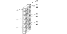
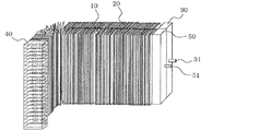
図1は、本発明の一実施の形態に係る熱交換器の斜視図である。図2は、図1の列跨ぎヘッダを示す斜視図である。図1、図2及び後述の図において、同一の符号を付したものは、同一の又はこれに相当するものであり、これは明細書の全文において共通している。更に、明細書全文に表れている構成要素の形態は、あくまで例示であってこれらの記載に限定されるものではない。
熱交換器1は、空気通過方向である列方向に配置された第1熱交換部10及び第2熱交換部20と、冷媒分配器としての入口ヘッダ30と、列跨ぎヘッダ40と、出口ヘッダ50とを備えている。
FIG. 1 is a perspective view of a heat exchanger according to an embodiment of the present invention. FIG. 2 is a perspective view showing the row-crossing header of FIG. In FIG. 1, FIG. 2, and the figure mentioned later, what attached | subjected the same code | symbol is the same or it corresponds, and this is common in the whole text of a specification. Furthermore, the forms of the constituent elements appearing in the entire specification are merely examples and are not limited to these descriptions.
The
第1熱交換部(出口熱交換部)10は、互いに間隔を空けて積層され、その間を空気が通過する複数のフィン11と、複数のフィン11を積層方向に貫通し、内部を冷媒が通過し、空気通過方向に対して垂直方向である段方向へ複数段設けられた扁平管(伝熱管)12とを有している。扁平管12は、図3に示すように冷媒流路となる貫通孔12aを複数有している。第2熱交換部(入口熱交換部)20は第1熱交換部10と同様の構成であり、複数のフィン21と複数の扁平管(伝熱管)22とを有している。なお、ここではフィン11の形状として板状フィンを示したが、必ずしも板状フィンでなくてもよい。例えば段方向に扁平管12と交互に積層して配置される波形状のフィン等でもよく、要は空気通過方向に空気が通過するように配置されたフィンであればよい。
The first heat exchanging section (outlet heat exchanging section) 10 is stacked with a space between each other, a plurality of
入口ヘッダ30は、第2熱交換部20の一端側に段方向に沿うように配置され、第2熱交換部20の全ての扁平管22に連通しており、冷媒入口配管31から流入した冷媒を各扁平管22に均等に分配して流入させる。
The
出口ヘッダ50は、第1熱交換部10の一端側に段方向に沿うように配置され、第1熱交換部10の全ての扁平管12に連通しており、各扁平管12を通過した冷媒を合流させて冷媒出口配管51から流出させる。
The
列跨ぎヘッダ40は、第1熱交換部10及び第2熱交換部20の他端側に段方向に沿うように配置され、第1熱交換部10及び第2熱交換部20を跨ぐように構成されている。列跨ぎヘッダ40は内部が中空に構成され、仕切板41により段方向に仕切られて扁平管12、22の段数と同数の部屋42が形成されている。そして、各部屋42のそれぞれに設けた2つの貫通孔43に、同一段の扁平管12、22の端部がそれぞれ接続されている。このように構成された各部屋42は、図1の矢印に示すように扁平管22を通過後の冷媒が流入し、扁平管12へ向けて折り返す折り返し流路となっている。
The row-
以上の構成により、第2熱交換部20の扁平管22の入口から第1熱交換部10の扁平管12の出口に至るまで段毎(部屋42毎)に独立した流路が形成されている。
With the above configuration, an independent flow path is formed for each stage (for each room 42) from the inlet of the
扁平管12、22、フィン11、21、入口ヘッダ30、列跨ぎヘッダ40及び出口ヘッダ50は例えばアルミ又はアルミ合金で形成されている。
The
以上の構成の熱交換器1を製造する際には、扁平管12、22、フィン11、21、入口ヘッダ30、列跨ぎヘッダ40、出口ヘッダ50を全て組み立てた状態で同時に炉中ロウ付け接合する。
When manufacturing the
図4は、図1の熱交換器が適用された冷凍サイクル装置の冷媒回路を示す図である。
冷凍サイクル装置60は、圧縮機61と、凝縮器62と、減圧装置としての膨張弁63と、蒸発器64とを備えている。凝縮器62と蒸発器64の少なくとも一方に、熱交換器1が用いられる。圧縮機61から吐出された冷媒は凝縮器62に流入し、凝縮器62を通過する空気と熱交換して高圧液冷媒となって流出する。凝縮器62を流出した高圧液冷媒は膨張弁63で減圧されて低圧二相冷媒となり、蒸発器64に流入する。蒸発器64に流入した低圧二相冷媒は、蒸発器64を通過する空気と熱交換して低圧ガス冷媒となり、再び圧縮機61に吸入される。
FIG. 4 is a diagram showing a refrigerant circuit of a refrigeration cycle apparatus to which the heat exchanger of FIG. 1 is applied.
The
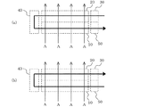
図5(a)は、図1の熱交換器を凝縮器として用いる場合の冷媒の流れを示す図であり、図1を平面的に見た状態での冷媒の流れを示している。図5(a)において太矢印は冷媒の流れ方向を示しており、細矢印Aは空気の流れを示している。
熱交換器1を凝縮器62として用いる場合は、空気の流れ方向Aに対して下流側から上流側に折り返すようにして冷媒を流す(以下、この流れを対向流という)。なお、この対向流に対し、図5(b)に示すように空気の流れ方向Aに対して上流側から下流側に折り返すようにして冷媒を流す平行流もあるが、平行流とする場合については後述する。
Fig.5 (a) is a figure which shows the flow of the refrigerant | coolant at the time of using the heat exchanger of FIG. 1 as a condenser, and has shown the flow of the refrigerant | coolant in the state which looked at FIG. 1 planarly. In Fig.5 (a), the thick arrow has shown the flow direction of the refrigerant | coolant, and the thin arrow A has shown the flow of the air.
When the
以下、図1及び図4を参照して熱交換器1を凝縮器62として用いる場合の冷媒の流れを説明する。
冷媒入口配管31から入口ヘッダ30内部に流入した冷媒は、ここで均等に分配されて第2熱交換部20の各扁平管22の入口にそれぞれに流入する。そして、各扁平管22を通過した各冷媒は、列跨ぎヘッダ40の各部屋42にそれぞれ流入する。そして、各冷媒は各部屋42内で折り返し、各扁平管12にそれぞれ流入する。
Hereinafter, the flow of the refrigerant when the
The refrigerant that has flowed into the
ここで、各部屋42のそれぞれには均等に分配された各冷媒が流入し、別の部屋42の冷媒と混ざることなく各部屋42から流出し、第1熱交換部10の各扁平管12に流入する。このため、各部屋42を流出した各冷媒は、均等分配状態を維持したまま各扁平管12に流入する。そして、各扁平管12を通過した各冷媒は、出口ヘッダ50で合流して冷媒出口配管51から外部に流出する。なお、熱交換器1を凝縮器62として用いる場合は、ガス状態で熱交換器1に流入することから、冷媒の均等分配は容易である。このため、必ずしも冷媒分配器としての入口ヘッダ30を備えていなくてもよく、単に第2熱交換部20の各扁平管22が内部で連通する構成のものとしてもよい。
Here, each equally distributed refrigerant flows into each
次に、冷媒を対向流で流すことによる効果について説明する。冷媒を対向流で流すことによる効果は、冷媒流路の入口から出口までの冷媒温度分布が関係している。 Next, the effect of flowing the refrigerant in the counterflow will be described. The effect of flowing the refrigerant in the counterflow is related to the refrigerant temperature distribution from the inlet to the outlet of the refrigerant flow path.
図6は、凝縮器の入口から出口までの冷媒流路における冷媒温度分布を示す図である。図6において横軸は冷媒流路、縦軸は温度を示している。なお、(a)は、R32、HFO1234YFのような単一冷媒、R410Aのような混合冷媒でも共沸冷媒、(b)は、HFO1234YFとR32を混合した非共沸冷媒の場合を示している。また、凝縮器62では、熱交換性能を向上するためサブクールをつけるようにしており、図6においてSC(=Tc−Tb)で示している。
FIG. 6 is a diagram illustrating a refrigerant temperature distribution in the refrigerant flow path from the inlet to the outlet of the condenser. In FIG. 6, the horizontal axis indicates the refrigerant flow path, and the vertical axis indicates the temperature. Note that (a) shows a single refrigerant such as R32 and HFO1234YF, an azeotropic refrigerant such as a mixed refrigerant such as R410A, and (b) shows a non-azeotropic refrigerant obtained by mixing HFO1234YF and R32. Further, the
図6(a)に示すように単一冷媒、共沸混合冷媒の場合、ガス冷媒は高温Taで流入し、凝縮器62を通過する空気との熱交換により温度が低下して凝縮温度Tcまで下がる。そして、冷媒は凝縮温度Tcで温度一定の気液二相状態を経て液状態に変化する。液状態となった冷媒は、凝縮温度Tcよりも更に温度低下してサブクールが付けられ、低温Tbとなって流出する。
As shown in FIG. 6A, in the case of a single refrigerant or an azeotropic refrigerant mixture, the gas refrigerant flows in at a high temperature Ta, and the temperature is lowered by heat exchange with the air passing through the
図6(b)に示すように非共沸冷媒の場合には、ガス冷媒は高温Ta’で流入し、凝縮器62を通過する空気との熱交換により温度が低下して凝縮温度Tc’まで下がる。非共沸冷媒は、ガスの飽和温度と液の飽和温度が異なり、気液二相状態においても冷媒温度が温度低下を続け、液状態に変化する。そして、液状態となった冷媒は、凝縮温度Tc’よりも更に温度低下してサブクールが付けられ、低温Tb’となって流出する。
As shown in FIG. 6B, in the case of a non-azeotropic refrigerant, the gas refrigerant flows in at a high temperature Ta ′, and the temperature is lowered by heat exchange with the air passing through the
凝縮器62では、サブクールを例えば10℃程度付けることが求められるため、入口から出口にわたる冷媒流路の後半においても、空気との熱交換量を十分に確保する必要がある。
Since the
凝縮器62において仮に平行流(図5(b)参照)とすると、第1熱交換部10側で熱交換後の空気が第2熱交換部20に流入することになる。このため、冷媒流路の後半で空気との温度差を十分に取れず、所望のサブクールをつけることができない可能性がある。これに対し、対向流とした場合は、冷媒流れの後半の冷媒が、熱交換前の空気と熱交換することになるため、温度差を十分に確保でき、安定してサブクールをつけることができる。
If the
凝縮器62において対向流とする効果は、単一冷媒、共沸冷媒の場合でも得られるが、非共沸冷媒の場合には特に効果的である。すなわち、非共沸冷媒の場合には、上述したようにガスの飽和温度と液の飽和温度とが異なり、気液二相域で温度勾配があるため、冷媒と空気との温度差を共沸冷媒の場合よりも確保できる。よって、更に効果的なのである。
The effect of the counterflow in the
以上では、熱交換器1を凝縮器62として用いる場合を説明したが、次に、蒸発器64として用いる場合について説明する。蒸発器64として用いる場合は、対向流及び平行流のどちらとしてもよいが、どちらかといえば対向流の方が好ましい。熱交換器1を蒸発器64として用いる場合で冷媒が非共沸冷媒であるときには、上述したように気液二相域で温度勾配があり、温度差が拡大して熱交換性能が向上するため、対向流とする方が高い効果が得られる。
The case where the
なお、蒸発器64では、熱交換性能を向上するためスーパーヒートをつけるが、スーパーヒートは大体1、2℃程度でありサブクールの10℃に比べて小さい。よって、対向流とすることによる効果は凝縮器62として用いる場合の方が高い。
In the
熱交換器1を蒸発器専用又は凝縮器専用として用いる場合には、対向流で冷媒を流すように図1の構成とすればよい。一方、図4の冷凍サイクル装置60に更に四方弁を設けて冷媒の流れ方向を切り換え、熱交換器1を蒸発器64又は凝縮器62として切り換えて用いる場合には、次の図7のように構成する。
When the
図7は、蒸発器又は凝縮器として切り換えて用いる熱交換器を示す図である。図7において点線矢印は蒸発器64の場合の冷媒の流れ、実線矢印は凝縮器62の場合の冷媒の流れを示している。
図7において、図1と異なるのは、出口ヘッダ50に代えて、冷媒を均等に分配する冷媒分配器としての機能を備えた出口ヘッダ50aを設けた点である。
FIG. 7 is a diagram showing a heat exchanger that is switched and used as an evaporator or a condenser. In FIG. 7, the dotted line arrow indicates the refrigerant flow in the case of the
7 differs from FIG. 1 in that an
このように構成した熱交換器1においては、蒸発器64として用いる場合には平行流、すなわち出口ヘッダ50a→第1熱交換部10→列跨ぎヘッダ40→第2熱交換部20→入口ヘッダ30の順に冷媒を流す。このように蒸発器64として用いる際には、出口ヘッダ50a側から冷媒が流入する。よって、気液二相状態で流入する冷媒を均等に分配して各扁平管12に流入させるよう、出口ヘッダ50aに冷媒分配器としての機能を備えるようにしている。一方、凝縮器62として用いる場合には対向流、すなわち入口ヘッダ30→第2熱交換部20→列跨ぎヘッダ40→第1熱交換部10→出口ヘッダ50aの順に冷媒を流す。
In the
以上説明したように本実施の形態によれば、第1熱交換部10及び第2熱交換部20における冷媒流路の入口から出口まで、各段の扁平管12、22内を通過する各冷媒が他の段の冷媒と合流することなく独立した流路を流れる。よって、入口における均等分配状態が出口まで良好に維持され、分配偏流を抑制することができる。その結果、熱交換器1の熱交換効率を高めることができ、この熱交換器1を有する冷凍サイクル装置60の高効率な運転を実現することができる。
As described above, according to the present embodiment, each refrigerant that passes through the
また、熱交換器1を凝縮器62として用いる場合には、対向流となるように冷媒を流すことにより、熱交換効率を向上することができる。なお、対向流とすることによる効果は、冷凍サイクル装置60内に封入する冷媒を非共沸冷媒とした場合に特に効果的である。
Moreover, when using the
なお、本発明の熱交換器は、図1に示した構造に限定されるものではなく、本発明の要旨を逸脱しない範囲で例えば以下の(1)〜(9)のように種々変形実施可能である。 Note that the heat exchanger of the present invention is not limited to the structure shown in FIG. 1, and can be variously modified as, for example, the following (1) to (9) without departing from the gist of the present invention. It is.
(1)本実施の形態では、列跨ぎヘッダ40において段毎に仕切板41を設けるとしたが、必ずしも段毎でなくてもよく、要は、列跨ぎヘッダ40の内部が、均等分配状態を維持できるように段方向に複数に仕切られていればよい。
均等分配状態を維持できるかどうかは、具体的には各部屋42におけるヘッド差が効いてくるため、ヘッド差を考慮して仕切板41を設ける間隔を決定すればよい。仕切板41を必要最低限だけ設けるようにした場合、コスト低減が可能となる。
(1) In the present embodiment, the
Specifically, whether or not the uniform distribution state can be maintained depends on the head difference in each
(2)熱交換器1における風速分布に応じて仕切板41の位置を決定するようにしてもよい。
熱交換器1に空気を送風する送風ファンからの風速は、熱交換器1の全面において均一とは限らず、風速分布が存在する。例えばビル用マルチエアコンの場合、熱交換器1の上部に送風ファンが設置されるため、熱交換器の上部の方が下部に比べて風速が速くなる。熱交換器1を蒸発器64として用いる場合において風速が速い部分は風速が遅い部分よりもガス化が進み、冷媒を均等分配しやすくなる。よって、風速が速い部分を通過する扁平管12、22が連通する列跨ぎヘッダ40部分については、仕切板41の間隔を広げて部屋42の高さ(段方向の長さ)を高く(長く)してもよい。
(2) The position of the
The wind speed from the blower fan that blows air to the
(3)本実施の形態では、熱交換器1が全体略I字状の例を示したが、図8に示すように全体略L字状とし、熱交換器1の一部が曲げて構成されていてもよい。
全体略L字状とする場合には、全体I字状に形成した熱交換器1を図9に示すように矢印方向にL曲げすることにより構成できる。なお、L曲げ後の状態において第1熱交換部10及び第2熱交換部20の両端部の位置が揃うように、図9に示すように折り曲げ前の状態で第1熱交換部10側を第2熱交換部20に比べて短く構成しておくことは言うまでもない。このように両端部の位置を揃える構成とすることで、冷媒入口配管31及び冷媒出口配管51に接続される外部配管の取り回しが容易となる。
(3) In the present embodiment, the example in which the
In the case of an overall L-shape, the
なお、熱交換器1をI字状とするかL字状とするかは、熱交換器1が設置される筐体内における熱交換器1の実装スペースを応じて決めればよく、実装スペースを最大限に利用して高密度に実装できる形状とすればよい。形状は、I字状やL字状以外にも、U字状や矩形状としてもよい。何れにしろ、実装スペース内に高密度に配置することで、高い熱交換効率を得ることができる。この場合も、第1熱交換部10及び第2熱交換部20の両端部の位置が揃うように構成する。
Whether the
(4)冷媒分配器として入口ヘッダ30を設けた構成を説明したが、入口ヘッダ30内に更に、分配偏流を抑制するための偏流抑制部材(例えば、冷媒の流れを絞るオリフィス)を設けてもよい。
(4) Although the configuration in which the
(5)冷媒分配器として、入口ヘッダ30に代えて冷媒を略均等に分配するディストリビュータを設けてもよい。
(5) Instead of the
(6)冷媒分配器として、入口ヘッダ30に代えて図10に示す冷媒分配器70としてもよい。
冷媒分配器70は、各扁平管12の端部に連通するヘッダ71とディストリビュータ74とを有する。ヘッダ71は、内部が1以上の仕切板72で上下方向に仕切られて複数の部屋73を形成している。そして、各部屋73のそれぞれが、各キャピラリチューブ75によりディストリビュータ74に接続されている。この冷媒分配器70では、ディストリビュータ74で略均等に分配された冷媒が各キャピラリチューブ75を介して各部屋73に流入する。
(6) As the refrigerant distributor, the
The
各部屋73の上下方向の長さは、仕切板72を設けずにヘッダ71内全体を連通した場合の上下方向の長さに比べて小さい。このため、重力によるヘッド差の影響が低減され、各部屋73のそれぞれにおいてその部屋73に連通する各扁平管22に、冷媒を均等に分配して流入させることができる。なお、コスト低減やキャピラリチューブ75の引き回しを考えると、仕切板72は段毎に設けず、図10に示したように複数段毎に設けた構成とする方が好ましいが、段毎に設けてももちろんよい。
The length in the vertical direction of each
(7)本実施の形態では、列跨ぎヘッダ40が上下方向に向くように配置した構成を示したが、図1において熱交換器1全体を90度回転させ、列跨ぎヘッダ40が左右方向に向くように配置した構成としてもよい。列跨ぎヘッダ40が上下方向に向くように配置した構成の場合、仕切板41が無い構成と比較するとヘッド差の影響の低減効果が高い。よって、本発明は、列跨ぎヘッダ40が上下方向に向く構成に適用した方がより効果的である。
(7) In the present embodiment, the configuration in which the row-crossing
(8)本実施の形態では、2列構成の例を図示して説明したが、3列以上としてもよい。この場合も2列構成の場合と同様の考え方で構成すればよい。すなわち、複数列の前記熱交換部のうち列方向両端の熱交換器は、冷媒が流入する入口熱交換部又は冷媒が流出する出口熱交換部となり、複数列の熱交換部において列方向に隣接するもの同士の複数段の伝熱管の一方の端部を列跨ぎヘッダで連通させる。そして、入口熱交換部の複数段の伝熱管の入口から流入した冷媒が、出口熱交換部の複数段の伝熱管の出口に至るまで列跨ぎヘッダ部分で折り返しながら流れる冷媒流路を形成する。そして、列跨ぎヘッダの内部を、段方向に複数に仕切って複数の部屋を構成し、冷媒流路が部屋毎に独立した構成とする。 (8) In the present embodiment, an example of a two-row configuration is illustrated and described, but three or more rows may be used. In this case, the same concept as in the case of the two-row configuration may be used. That is, the heat exchangers at both ends in the row direction among the plurality of rows of heat exchange units are an inlet heat exchange unit into which refrigerant flows or an outlet heat exchange unit from which refrigerant flows out, and is adjacent in the row direction in the plurality of rows of heat exchange units. One end portion of the heat transfer tubes of the plurality of stages to be communicated is communicated with the header across the rows. And the refrigerant | coolant flow path into which the refrigerant | coolant which flowed in from the inlet of the multi stage heat exchanger tube of an inlet heat exchange part flows in the row | line | column straddle header part until it reaches the exit of the multi stage heat exchanger tube of an exit heat exchanger part is formed. And the inside of a row | line | column straddling header is divided into plurality by the step direction, a some room is comprised, and it is set as the structure by which the refrigerant | coolant flow path became independent for every room.
(9)本実施の形態では伝熱管を扁平管としたが、必ずしも扁平管でなくてもよく、円管としてもよい。 (9) Although the heat transfer tube is a flat tube in the present embodiment, it is not necessarily a flat tube and may be a circular tube.
1 熱交換器、10 第1熱交換部、11 フィン、12 伝熱管(扁平管)、12a 貫通孔、20 第2熱交換部、21 フィン、22 伝熱管(扁平管)、30 入口ヘッダ、31 冷媒入口配管、40 列跨ぎヘッダ、41 仕切板、42 部屋、43 貫通孔、50 出口ヘッダ、50a 出口ヘッダ、51 冷媒出口配管、60 冷凍サイクル装置、61 圧縮機、62 凝縮器、63 膨張弁、64 蒸発器、70 冷媒分配器、71 ヘッダ、72 仕切板、73 部屋、74 ディストリビュータ、75 キャピラリチューブ。
DESCRIPTION OF
Claims (11)
前記複数列の前記熱交換部のうち列方向両端の熱交換部は、冷媒が流入する入口熱交換部又は冷媒が流出する出口熱交換部となり、
前記複数列の前記熱交換部において列方向に隣接するもの同士の前記複数段の伝熱管の一方の端部が列跨ぎヘッダで連通しており、前記入口熱交換部の前記複数段の伝熱管の入口から流入した冷媒が、前記出口熱交換部の前記複数段の伝熱管の出口に至るまで前記列跨ぎヘッダ部分で折り返しながら流れる冷媒流路が形成されており、
前記列跨ぎヘッダの内部は、段方向に複数に仕切られて複数の部屋を構成しており、前記冷媒流路は前記部屋毎に独立しており、
前記入口熱交換部の前記複数段の伝熱管において前記列跨ぎヘッダに接続されない他方の端部は冷媒入口側の端部となっており、
前記複数段の伝熱管の前記冷媒入口側の端部に冷媒を分配して流入させる冷媒分配器を更に有し、
前記冷媒分配器は、前記複数段の伝熱管の冷媒入口側の端部に段方向に沿うように配置されて前記冷媒入口側の端部に連通し、且つ、内部が1以上の仕切板で上下方向に仕切られて、前記伝熱管の段数よりも少ない複数の部屋が形成されたヘッダと、冷媒を略均等に分配するディストリビュータとを有し、前記複数の部屋のそれぞれが各キャピラリチューブにより前記ディストリビュータに接続された構成を有する
ことを特徴とする熱交換器。 A refrigerant in a gas-liquid two-phase state passes inside, and is arranged so that air passes in the air passage direction, and a plurality of heat transfer tubes provided in a plurality of stages in a step direction perpendicular to the air passage direction. A plurality of fins and the heat exchanging portions are arranged in a plurality of rows in a row direction that is the air passing direction,
Among the heat exchange units of the plurality of rows, the heat exchange units at both ends in the column direction become an inlet heat exchange unit into which refrigerant flows or an outlet heat exchange unit from which refrigerant flows out,
One end of the plurality of stages of heat transfer tubes adjacent to each other in the row direction in the heat exchange section of the plurality of rows communicates with a row header, and the plurality of stages of heat transfer tubes of the inlet heat exchange section A refrigerant flow path is formed in which the refrigerant flowing from the inlet of the outlet flows back at the header across the row until reaching the outlet of the heat transfer tubes of the plurality of stages of the outlet heat exchange unit,
The inside of the row-crossing header is partitioned into a plurality of stages in the step direction to form a plurality of rooms, and the refrigerant flow path is independent for each room ,
The other end of the plurality of heat transfer tubes of the inlet heat exchanging portion that is not connected to the row header is an end on the refrigerant inlet side,
A refrigerant distributor for distributing and flowing the refrigerant into the refrigerant inlet side end of the plurality of stages of heat transfer tubes;
The refrigerant distributor is arranged at a refrigerant inlet side end of the plurality of stages of heat transfer tubes along the step direction, communicates with the refrigerant inlet side end, and has one or more partition plates inside. A header that is partitioned in a vertical direction and has a plurality of chambers less than the number of stages of the heat transfer tubes, and a distributor that distributes the refrigerant substantially evenly, each of the plurality of chambers being separated by the capillary tube A heat exchanger having a configuration connected to a distributor .
Priority Applications (1)
| Application Number | Priority Date | Filing Date | Title |
|---|---|---|---|
| JP2015133722A JP6061994B2 (en) | 2012-04-26 | 2015-07-02 | Heat exchanger, refrigeration cycle apparatus and air conditioner equipped with this heat exchanger |
Applications Claiming Priority (3)
| Application Number | Priority Date | Filing Date | Title |
|---|---|---|---|
| JPPCT/JP2012/002872 | 2012-04-26 | ||
| PCT/JP2012/002872 WO2013160954A1 (en) | 2012-04-26 | 2012-04-26 | Heat exchanger, and refrigerating cycle device equipped with heat exchanger |
| JP2015133722A JP6061994B2 (en) | 2012-04-26 | 2015-07-02 | Heat exchanger, refrigeration cycle apparatus and air conditioner equipped with this heat exchanger |
Related Parent Applications (1)
| Application Number | Title | Priority Date | Filing Date |
|---|---|---|---|
| JP2014512600A Division JP5840291B2 (en) | 2012-04-26 | 2013-04-23 | Heat exchanger, refrigeration cycle apparatus and air conditioner equipped with this heat exchanger |
Publications (2)
| Publication Number | Publication Date |
|---|---|
| JP2015200497A JP2015200497A (en) | 2015-11-12 |
| JP6061994B2 true JP6061994B2 (en) | 2017-01-18 |
Family
ID=54551888
Family Applications (1)
| Application Number | Title | Priority Date | Filing Date |
|---|---|---|---|
| JP2015133722A Expired - Fee Related JP6061994B2 (en) | 2012-04-26 | 2015-07-02 | Heat exchanger, refrigeration cycle apparatus and air conditioner equipped with this heat exchanger |
Country Status (1)
| Country | Link |
|---|---|
| JP (1) | JP6061994B2 (en) |
Families Citing this family (11)
| Publication number | Priority date | Publication date | Assignee | Title |
|---|---|---|---|---|
| JP6693534B2 (en) * | 2018-01-31 | 2020-05-13 | ダイキン工業株式会社 | Heat exchanger or refrigeration system having heat exchanger |
| ES2967038T3 (en) * | 2018-04-05 | 2024-04-25 | Mitsubishi Electric Corp | Distributor and heat exchanger |
| WO2019244408A1 (en) * | 2018-06-19 | 2019-12-26 | シャープ株式会社 | Heat exchanger and air conditioner |
| DE112020003525T5 (en) * | 2019-07-23 | 2022-04-14 | Denso Corporation | heat exchanger |
| JP6881624B1 (en) * | 2020-01-22 | 2021-06-02 | 株式会社富士通ゼネラル | Heat exchanger |
| CN114340297B (en) * | 2020-09-29 | 2025-08-01 | 台达电子工业股份有限公司 | Water cooling device and current collector thereof |
| JP6918258B1 (en) * | 2021-01-28 | 2021-08-11 | 日立ジョンソンコントロールズ空調株式会社 | Air conditioner and heat exchanger |
| JP6990795B1 (en) | 2021-01-28 | 2022-01-12 | 日立ジョンソンコントロールズ空調株式会社 | Indoor unit and outdoor unit |
| WO2022208733A1 (en) * | 2021-03-31 | 2022-10-06 | 三菱電機株式会社 | Heat exchanger |
| CN114216166B (en) * | 2021-11-25 | 2023-04-07 | 青岛海信日立空调系统有限公司 | Air conditioner |
| WO2023166612A1 (en) * | 2022-03-02 | 2023-09-07 | 三菱電機株式会社 | Heat exchanger and method for manufacturing heat exchanger |
Family Cites Families (8)
| Publication number | Priority date | Publication date | Assignee | Title |
|---|---|---|---|---|
| JPS6038364U (en) * | 1983-08-18 | 1985-03-16 | シャープ株式会社 | Heat exchanger |
| JPH06300477A (en) * | 1993-04-12 | 1994-10-28 | Matsushita Refrig Co Ltd | Heat exchanger |
| JPH09145187A (en) * | 1995-11-24 | 1997-06-06 | Hitachi Ltd | Air conditioner |
| JP4106726B2 (en) * | 1998-02-24 | 2008-06-25 | 株式会社デンソー | Refrigerant evaporator |
| US6745827B2 (en) * | 2001-09-29 | 2004-06-08 | Halla Climate Control Corporation | Heat exchanger |
| EP1856588A4 (en) * | 2005-02-02 | 2010-07-21 | Carrier Corp | Parallel flow heat exchanger for heat pump applications |
| DE112008003011B4 (en) * | 2007-11-09 | 2023-03-23 | Hanon Systems | heat exchanger |
| CN102278908B (en) * | 2011-09-16 | 2013-06-26 | 四川长虹空调有限公司 | Microchannel heat exchanger |
-
2015
- 2015-07-02 JP JP2015133722A patent/JP6061994B2/en not_active Expired - Fee Related
Also Published As
| Publication number | Publication date |
|---|---|
| JP2015200497A (en) | 2015-11-12 |
Similar Documents
| Publication | Publication Date | Title |
|---|---|---|
| JP6061994B2 (en) | Heat exchanger, refrigeration cycle apparatus and air conditioner equipped with this heat exchanger | |
| WO2013161799A1 (en) | Heat exchanger, and refrigerating cycle device equipped with heat exchanger | |
| JP5901748B2 (en) | Refrigerant distributor, heat exchanger equipped with this refrigerant distributor, refrigeration cycle apparatus, and air conditioner | |
| JP6017047B2 (en) | Heat exchanger, air conditioner, refrigeration cycle apparatus, and heat exchanger manufacturing method | |
| US9494368B2 (en) | Heat exchanger and air conditioner | |
| US9651317B2 (en) | Heat exchanger and air conditioner | |
| US10041710B2 (en) | Heat exchanger and air conditioner | |
| CN105473977B (en) | Heat exchanger and air conditioner | |
| JP2018100800A (en) | Heat exchanger and air conditioner | |
| JP5716496B2 (en) | Heat exchanger and air conditioner | |
| JP6742112B2 (en) | Heat exchanger and air conditioner | |
| JP6611335B2 (en) | Heat exchanger and air conditioner | |
| JP5840291B2 (en) | Heat exchanger, refrigeration cycle apparatus and air conditioner equipped with this heat exchanger | |
| JP6171765B2 (en) | Heat exchanger | |
| JPWO2021117107A1 (en) | Distributor, heat exchanger with distributor and air conditioner with the heat exchanger | |
| WO2023199466A1 (en) | Heat exchanger, and air conditioning device including same | |
| WO2023281731A1 (en) | Heat exchanger and air conditioner |
Legal Events
| Date | Code | Title | Description |
|---|---|---|---|
| A977 | Report on retrieval |
Free format text: JAPANESE INTERMEDIATE CODE: A971007 Effective date: 20160406 |
|
| A131 | Notification of reasons for refusal |
Free format text: JAPANESE INTERMEDIATE CODE: A131 Effective date: 20160412 |
|
| A521 | Request for written amendment filed |
Free format text: JAPANESE INTERMEDIATE CODE: A523 Effective date: 20160606 |
|
| TRDD | Decision of grant or rejection written | ||
| A01 | Written decision to grant a patent or to grant a registration (utility model) |
Free format text: JAPANESE INTERMEDIATE CODE: A01 Effective date: 20161115 |
|
| A61 | First payment of annual fees (during grant procedure) |
Free format text: JAPANESE INTERMEDIATE CODE: A61 Effective date: 20161213 |
|
| R150 | Certificate of patent or registration of utility model |
Ref document number: 6061994 Country of ref document: JP Free format text: JAPANESE INTERMEDIATE CODE: R150 |
|
| R250 | Receipt of annual fees |
Free format text: JAPANESE INTERMEDIATE CODE: R250 |
|
| R250 | Receipt of annual fees |
Free format text: JAPANESE INTERMEDIATE CODE: R250 |
|
| R250 | Receipt of annual fees |
Free format text: JAPANESE INTERMEDIATE CODE: R250 |
|
| R250 | Receipt of annual fees |
Free format text: JAPANESE INTERMEDIATE CODE: R250 |
|
| R250 | Receipt of annual fees |
Free format text: JAPANESE INTERMEDIATE CODE: R250 |
|
| LAPS | Cancellation because of no payment of annual fees |