JP6087632B2 - 電力供給装置及び記録装置 - Google Patents
電力供給装置及び記録装置 Download PDFInfo
- Publication number
- JP6087632B2 JP6087632B2 JP2013002840A JP2013002840A JP6087632B2 JP 6087632 B2 JP6087632 B2 JP 6087632B2 JP 2013002840 A JP2013002840 A JP 2013002840A JP 2013002840 A JP2013002840 A JP 2013002840A JP 6087632 B2 JP6087632 B2 JP 6087632B2
- Authority
- JP
- Japan
- Prior art keywords
- power supply
- voltage
- power
- circuit
- supply circuit
- Prior art date
- Legal status (The legal status is an assumption and is not a legal conclusion. Google has not performed a legal analysis and makes no representation as to the accuracy of the status listed.)
- Expired - Fee Related
Links
Images





Classifications
-
- G—PHYSICS
- G06—COMPUTING OR CALCULATING; COUNTING
- G06F—ELECTRIC DIGITAL DATA PROCESSING
- G06F1/00—Details not covered by groups G06F3/00 - G06F13/00 and G06F21/00
- G06F1/26—Power supply means, e.g. regulation thereof
-
- H—ELECTRICITY
- H02—GENERATION; CONVERSION OR DISTRIBUTION OF ELECTRIC POWER
- H02M—APPARATUS FOR CONVERSION BETWEEN AC AND AC, BETWEEN AC AND DC, OR BETWEEN DC AND DC, AND FOR USE WITH MAINS OR SIMILAR POWER SUPPLY SYSTEMS; CONVERSION OF DC OR AC INPUT POWER INTO SURGE OUTPUT POWER; CONTROL OR REGULATION THEREOF
- H02M1/00—Details of apparatus for conversion
- H02M1/36—Means for starting or stopping converters
-
- H—ELECTRICITY
- H02—GENERATION; CONVERSION OR DISTRIBUTION OF ELECTRIC POWER
- H02H—EMERGENCY PROTECTIVE CIRCUIT ARRANGEMENTS
- H02H7/00—Emergency protective circuit arrangements specially adapted for specific types of electric machines or apparatus or for sectionalised protection of cable or line systems, and effecting automatic switching in the event of an undesired change from normal working conditions
- H02H7/10—Emergency protective circuit arrangements specially adapted for specific types of electric machines or apparatus or for sectionalised protection of cable or line systems, and effecting automatic switching in the event of an undesired change from normal working conditions for converters; for rectifiers
- H02H7/12—Emergency protective circuit arrangements specially adapted for specific types of electric machines or apparatus or for sectionalised protection of cable or line systems, and effecting automatic switching in the event of an undesired change from normal working conditions for converters; for rectifiers for static converters or rectifiers
- H02H7/125—Emergency protective circuit arrangements specially adapted for specific types of electric machines or apparatus or for sectionalised protection of cable or line systems, and effecting automatic switching in the event of an undesired change from normal working conditions for converters; for rectifiers for static converters or rectifiers for rectifiers
- H02H7/1255—Emergency protective circuit arrangements specially adapted for specific types of electric machines or apparatus or for sectionalised protection of cable or line systems, and effecting automatic switching in the event of an undesired change from normal working conditions for converters; for rectifiers for static converters or rectifiers for rectifiers responsive to internal faults, e.g. by monitoring ripple in output voltage
-
- H—ELECTRICITY
- H02—GENERATION; CONVERSION OR DISTRIBUTION OF ELECTRIC POWER
- H02M—APPARATUS FOR CONVERSION BETWEEN AC AND AC, BETWEEN AC AND DC, OR BETWEEN DC AND DC, AND FOR USE WITH MAINS OR SIMILAR POWER SUPPLY SYSTEMS; CONVERSION OF DC OR AC INPUT POWER INTO SURGE OUTPUT POWER; CONTROL OR REGULATION THEREOF
- H02M3/00—Conversion of DC power input into DC power output
- H02M3/02—Conversion of DC power input into DC power output without intermediate conversion into AC
- H02M3/04—Conversion of DC power input into DC power output without intermediate conversion into AC by static converters
- H02M3/10—Conversion of DC power input into DC power output without intermediate conversion into AC by static converters using discharge tubes with control electrode or semiconductor devices with control electrode
- H02M3/145—Conversion of DC power input into DC power output without intermediate conversion into AC by static converters using discharge tubes with control electrode or semiconductor devices with control electrode using devices of a triode or transistor type requiring continuous application of a control signal
- H02M3/155—Conversion of DC power input into DC power output without intermediate conversion into AC by static converters using discharge tubes with control electrode or semiconductor devices with control electrode using devices of a triode or transistor type requiring continuous application of a control signal using semiconductor devices only
- H02M3/156—Conversion of DC power input into DC power output without intermediate conversion into AC by static converters using discharge tubes with control electrode or semiconductor devices with control electrode using devices of a triode or transistor type requiring continuous application of a control signal using semiconductor devices only with automatic control of output voltage or current, e.g. switching regulators
-
- H—ELECTRICITY
- H02—GENERATION; CONVERSION OR DISTRIBUTION OF ELECTRIC POWER
- H02M—APPARATUS FOR CONVERSION BETWEEN AC AND AC, BETWEEN AC AND DC, OR BETWEEN DC AND DC, AND FOR USE WITH MAINS OR SIMILAR POWER SUPPLY SYSTEMS; CONVERSION OF DC OR AC INPUT POWER INTO SURGE OUTPUT POWER; CONTROL OR REGULATION THEREOF
- H02M3/00—Conversion of DC power input into DC power output
- H02M3/02—Conversion of DC power input into DC power output without intermediate conversion into AC
- H02M3/04—Conversion of DC power input into DC power output without intermediate conversion into AC by static converters
- H02M3/10—Conversion of DC power input into DC power output without intermediate conversion into AC by static converters using discharge tubes with control electrode or semiconductor devices with control electrode
- H02M3/145—Conversion of DC power input into DC power output without intermediate conversion into AC by static converters using discharge tubes with control electrode or semiconductor devices with control electrode using devices of a triode or transistor type requiring continuous application of a control signal
- H02M3/155—Conversion of DC power input into DC power output without intermediate conversion into AC by static converters using discharge tubes with control electrode or semiconductor devices with control electrode using devices of a triode or transistor type requiring continuous application of a control signal using semiconductor devices only
- H02M3/156—Conversion of DC power input into DC power output without intermediate conversion into AC by static converters using discharge tubes with control electrode or semiconductor devices with control electrode using devices of a triode or transistor type requiring continuous application of a control signal using semiconductor devices only with automatic control of output voltage or current, e.g. switching regulators
- H02M3/1566—Conversion of DC power input into DC power output without intermediate conversion into AC by static converters using discharge tubes with control electrode or semiconductor devices with control electrode using devices of a triode or transistor type requiring continuous application of a control signal using semiconductor devices only with automatic control of output voltage or current, e.g. switching regulators with means for compensating against rapid load changes, e.g. with auxiliary current source, with dual mode control or with inductance variation
Landscapes
- Engineering & Computer Science (AREA)
- Power Engineering (AREA)
- Theoretical Computer Science (AREA)
- Physics & Mathematics (AREA)
- General Engineering & Computer Science (AREA)
- General Physics & Mathematics (AREA)
- Dc-Dc Converters (AREA)
Description
図1は本発明の代表的な実施例であるインクジェット記録装置1の構成の概要を示す外観斜視図である。
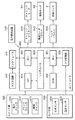
図2は図1に示した記録装置の制御構成を示すブロック図である。
Claims (8)
- 商用電源から生成されるDC電源に基づいて装置各部に電力を供給する電力供給装置であって、
前記DC電源の入力電圧を監視する監視手段と、
前記監視手段により監視される入力電圧が予め定められた閾値を下回ったときに前記電力を供給する集積回路に対してリセット信号を出力するリセット回路と、
前記リセット信号の出力に同期して前記集積回路に対する電力の供給を停止するように構成された電源回路と、
前記電源回路の出力に接続され、前記リセット信号の出力と同時に動作して、前記電源回路からの出力電圧の変動を緩和する緩和手段とを有し、
前記電源回路は、出力電圧の異なる第1の電源回路及び第2の電源回路を含み、
前記緩和手段は、前記第1の電源回路及び第2の電源回路の内の1つに接続され、
前記第1の電源回路からの出力電圧は、前記第2の電源回路からの出力電圧より高く、
前記第1の電源回路を前記集積回路の外部I/O用電源とし、
前記第2の電源回路を前記集積回路の内部コア用電源とし、
前記緩和手段は、前記第2の電源回路からの電力の一部が供給されるダミー負荷であり、
前記リセット信号の出力と同時に前記第1の電源回路からの電力供給を停止するとともに、前記ダミー負荷に対して前記第2の電源回路から電力の一部が供給され始め、予め定められた遅延時間の経過後に前記第2の電源回路からの出力を停止することを特徴とする電力供給装置。 - 前記第1の電源回路及び前記第2の電源回路はそれぞれ、バック型DC−DCコンバータであることを特徴とする請求項1に記載の電力供給装置。
- 前記電源回路はコイルを有することを特徴とする請求項1に記載の電力供給装置。
- 請求項1乃至3のいずれか1項に記載の電力供給装置を備えた記録装置。
- 電力供給装置であって、
第1の電圧に基づいて、前記電力供給装置の外部の装置へ供給するための第2の電圧を生成する電圧生成手段と、
前記第1の電圧を監視する監視手段と、
前記監視手段により監視される第1の電圧が予め定められた閾値を下回ったときに、前記外部の装置を低消費電力状態に移行させるための信号を生成する信号の生成手段と、
前記電圧生成手段の出力に接続され、前記信号の生成手段によって生成された信号に基づいて、前記第2の電圧の変動を緩和する緩和手段とを有し、
前記電圧生成手段は、前記信号の生成手段が前記信号を生成してから予め定められた時間が経過した後に、前記第2の電圧の生成を停止することを特徴とする電力供給装置。 - 前記電圧生成手段は、コイルを有することを特徴とする請求項5に記載の電力供給装置。
- 前記緩和手段は、予め定められた電力を消費することを特徴とする請求項5に記載の電力供給装置。
- 請求項5乃至7のいずれか1項に記載の電力供給装置を備えた記録装置。
Priority Applications (1)
| Application Number | Priority Date | Filing Date | Title |
|---|---|---|---|
| JP2013002840A JP6087632B2 (ja) | 2012-01-30 | 2013-01-10 | 電力供給装置及び記録装置 |
Applications Claiming Priority (3)
| Application Number | Priority Date | Filing Date | Title |
|---|---|---|---|
| JP2012017267 | 2012-01-30 | ||
| JP2012017267 | 2012-01-30 | ||
| JP2013002840A JP6087632B2 (ja) | 2012-01-30 | 2013-01-10 | 電力供給装置及び記録装置 |
Publications (2)
| Publication Number | Publication Date |
|---|---|
| JP2013179823A JP2013179823A (ja) | 2013-09-09 |
| JP6087632B2 true JP6087632B2 (ja) | 2017-03-01 |
Family
ID=48870071
Family Applications (1)
| Application Number | Title | Priority Date | Filing Date |
|---|---|---|---|
| JP2013002840A Expired - Fee Related JP6087632B2 (ja) | 2012-01-30 | 2013-01-10 | 電力供給装置及び記録装置 |
Country Status (2)
| Country | Link |
|---|---|
| US (1) | US9195287B2 (ja) |
| JP (1) | JP6087632B2 (ja) |
Families Citing this family (5)
| Publication number | Priority date | Publication date | Assignee | Title |
|---|---|---|---|---|
| JP6455079B2 (ja) * | 2014-10-31 | 2019-01-23 | 株式会社リコー | 電源装置、画像形成装置および制御方法 |
| US10073486B2 (en) * | 2016-08-29 | 2018-09-11 | Infineon Technologies Ag | System and method for supply current shaping |
| EP3410591B1 (en) * | 2017-06-01 | 2020-03-25 | Vestel Elektronik Sanayi ve Ticaret A.S. | Energy supply system and energy supply method |
| JP7102212B2 (ja) | 2018-04-27 | 2022-07-19 | キヤノン株式会社 | 電子機器、電子機器の制御方法、及びプログラム |
| JP2020014357A (ja) | 2018-07-20 | 2020-01-23 | キヤノン株式会社 | モータ駆動回路、その制御方法、プログラム、及び記録装置 |
Family Cites Families (12)
| Publication number | Priority date | Publication date | Assignee | Title |
|---|---|---|---|---|
| JP3389524B2 (ja) * | 1999-02-23 | 2003-03-24 | 松下電器産業株式会社 | スイッチングレギュレータ、dc/dc変換器、およびスイッチングレギュレータを備えたlsiシステム |
| JP4647747B2 (ja) * | 2000-06-08 | 2011-03-09 | 富士通セミコンダクター株式会社 | Dc−dcコンバータ及びdc−dcコンバータ用半導体集積回路装置 |
| JP2004129333A (ja) * | 2002-09-30 | 2004-04-22 | Seiko Epson Corp | 電源回路及び電圧生成回路 |
| JP2005020927A (ja) | 2003-06-27 | 2005-01-20 | Shindengen Electric Mfg Co Ltd | Dc−dcコンバータ |
| JP3848311B2 (ja) | 2003-09-16 | 2006-11-22 | キヤノン株式会社 | 電子機器及び電力供給方法 |
| JP2005130616A (ja) | 2003-10-23 | 2005-05-19 | Matsushita Electric Ind Co Ltd | 電源システム |
| US7693611B2 (en) * | 2003-12-31 | 2010-04-06 | Silicon Laboratories, Inc. | Power supply control using supply power transition control and dynamic controller parameter(s) |
| JP4762134B2 (ja) * | 2004-05-07 | 2011-08-31 | パナソニック株式会社 | 共振型スイッチング電源装置 |
| US7492560B2 (en) * | 2004-12-13 | 2009-02-17 | Seagate Technology Llc | ASIC latch-up recovery circuit |
| JP2008067454A (ja) * | 2006-09-06 | 2008-03-21 | Rohm Co Ltd | Dc/dcコンバータ |
| JP5080898B2 (ja) * | 2007-08-08 | 2012-11-21 | キヤノン株式会社 | 電子機器及び電子機器の制御方法 |
| JP2010004622A (ja) * | 2008-06-18 | 2010-01-07 | Fujitsu Ten Ltd | 電源装置 |
-
2013
- 2013-01-10 JP JP2013002840A patent/JP6087632B2/ja not_active Expired - Fee Related
- 2013-01-16 US US13/742,883 patent/US9195287B2/en not_active Expired - Fee Related
Also Published As
| Publication number | Publication date |
|---|---|
| US20130194841A1 (en) | 2013-08-01 |
| US9195287B2 (en) | 2015-11-24 |
| JP2013179823A (ja) | 2013-09-09 |
Similar Documents
| Publication | Publication Date | Title |
|---|---|---|
| JP4944654B2 (ja) | 電源装置、および記録装置 | |
| US7315159B2 (en) | Power supply for switching operation, electronic apparatus including the same, and method of controlling the same | |
| JP4356977B2 (ja) | 電源装置及び該電源装置を備える記録装置 | |
| JP6087632B2 (ja) | 電力供給装置及び記録装置 | |
| US10350920B2 (en) | Printing apparatus and power supply unit for printing apparatus | |
| JP3631163B2 (ja) | インクジェット記録装置 | |
| JP5451201B2 (ja) | 電力供給回路を備えた機器 | |
| JP5776237B2 (ja) | 容量性負荷駆動回路および流体噴射装置 | |
| US7898231B2 (en) | Integrated circuit and electronic apparatus | |
| US6761424B2 (en) | Image print apparatus and control method thereof | |
| JP2014000743A (ja) | 記録装置 | |
| US8664799B2 (en) | Apparatus including power supply circuit | |
| JP2010157477A (ja) | Led点灯制御装置、その装置を用いた記録装置、及びled点灯制御方法 | |
| JP5476933B2 (ja) | 液体吐出装置 | |
| US8757759B2 (en) | Temperature detecting apparatus | |
| US10250148B2 (en) | Printing apparatus, control method thereof, and power supply circuit therefor | |
| JP2009119714A (ja) | 記録ヘッド及び記録装置 | |
| JP4471350B2 (ja) | 電源装置、及びその装置を用いた記録装置 | |
| US8876234B2 (en) | Power supply device, power supply device control method, and image forming apparatus | |
| JP7374617B2 (ja) | 電源装置および画像記録装置 | |
| US20240362446A1 (en) | Image recording apparatus and method of controlling image recording apparatus | |
| JP2008289285A (ja) | 直流電圧変換回路、記録装置及び直流電圧変換回路の制御方法 | |
| JP2015217534A (ja) | 制御システム、画像形成装置、制御方法およびプログラム | |
| JP2016107446A (ja) | 記録装置及び記録ヘッドの故障検出方法 | |
| JP2009208253A (ja) | 電力供給制御装置、記録装置、及び電力供給制御方法 |
Legal Events
| Date | Code | Title | Description |
|---|---|---|---|
| A871 | Explanation of circumstances concerning accelerated examination |
Free format text: JAPANESE INTERMEDIATE CODE: A871 Effective date: 20140515 |
|
| A621 | Written request for application examination |
Free format text: JAPANESE INTERMEDIATE CODE: A621 Effective date: 20140515 |
|
| A621 | Written request for application examination |
Free format text: JAPANESE INTERMEDIATE CODE: A621 Effective date: 20160105 |
|
| A977 | Report on retrieval |
Free format text: JAPANESE INTERMEDIATE CODE: A971007 Effective date: 20161012 |
|
| A131 | Notification of reasons for refusal |
Free format text: JAPANESE INTERMEDIATE CODE: A131 Effective date: 20161014 |
|
| A521 | Request for written amendment filed |
Free format text: JAPANESE INTERMEDIATE CODE: A523 Effective date: 20161208 |
|
| TRDD | Decision of grant or rejection written | ||
| A01 | Written decision to grant a patent or to grant a registration (utility model) |
Free format text: JAPANESE INTERMEDIATE CODE: A01 Effective date: 20170105 |
|
| A61 | First payment of annual fees (during grant procedure) |
Free format text: JAPANESE INTERMEDIATE CODE: A61 Effective date: 20170202 |
|
| R151 | Written notification of patent or utility model registration |
Ref document number: 6087632 Country of ref document: JP Free format text: JAPANESE INTERMEDIATE CODE: R151 |
|
| LAPS | Cancellation because of no payment of annual fees |