JP6091925B2 - Vacuum pump - Google Patents
Vacuum pump Download PDFInfo
- Publication number
- JP6091925B2 JP6091925B2 JP2013036784A JP2013036784A JP6091925B2 JP 6091925 B2 JP6091925 B2 JP 6091925B2 JP 2013036784 A JP2013036784 A JP 2013036784A JP 2013036784 A JP2013036784 A JP 2013036784A JP 6091925 B2 JP6091925 B2 JP 6091925B2
- Authority
- JP
- Japan
- Prior art keywords
- casing
- bearing
- vacuum pump
- rotors
- rotor
- Prior art date
- Legal status (The legal status is an assumption and is not a legal conclusion. Google has not performed a legal analysis and makes no representation as to the accuracy of the status listed.)
- Active
Links
Images


Landscapes
- Applications Or Details Of Rotary Compressors (AREA)
Description
本発明は、気体を中真空から大気圧まで圧縮する取付姿勢の自由な真空ポンプに係り、特に軽量で簡易な構造の真空ポンプに関するものである。 The present invention relates to a vacuum pump having a free mounting posture for compressing gas from medium vacuum to atmospheric pressure, and more particularly to a vacuum pump having a light weight and a simple structure.
スパッタリング装置、ヘリウムリークディテクター、SEM等の分析装置等の用途に、気体を中真空から大気圧まで圧縮できる排気能力を持つ真空ポンプが用いられている。また、ターボ分子ポンプ等の高真空ポンプの粗引き用の真空ポンプとして、さらに、真空乾燥・真空張り合わせ装置等のように水蒸気等のガスを吸引する真空ポンプとしても、上記排気能力を持つ真空ポンプが用いられている。 A vacuum pump having an exhaust capability capable of compressing a gas from a medium vacuum to an atmospheric pressure is used for applications such as a sputtering apparatus, a helium leak detector, and an analysis apparatus such as an SEM. Moreover, as a vacuum pump for roughing a high vacuum pump such as a turbo molecular pump, and also as a vacuum pump for sucking a gas such as water vapor such as a vacuum drying / vacuum laminating apparatus, a vacuum pump having the above-mentioned exhaust capability Is used.
小容量で小型軽量の真空ポンプとしては、油回転ポンプが主流である。しかしながら、真空チャンバーへの油蒸気の逆拡散(真空チャンバーやワークの油汚染)、排気ラインの油汚染(火災の危険)、環境汚染、油飛散による油の減少、水分混入等による油の劣化、定期的に必要な油補充・油交換等の種々の問題がある。特に、真空ポンプ用のフッ素系の油は高価であり、交換作業も面倒である。 Oil rotary pumps are the mainstream as small-capacity, light-weight vacuum pumps. However, the reverse diffusion of oil vapor into the vacuum chamber (contamination of oil in the vacuum chamber and workpiece), oil contamination in the exhaust line (fire hazard), environmental contamination, oil reduction due to oil splashing, oil deterioration due to moisture mixing, There are various problems such as oil replenishment and oil change required regularly. In particular, fluorinated oil for vacuum pumps is expensive and troublesome to replace.
そのため、近年、油回転ポンプに代替する真空ポンプとして、スクロール型ドライ真空ポンプが登場してきた。スクロール型ドライ真空ポンプは、オイルフリーであり、スクロールの揺動運動により真空から大気圧まで連続的に圧縮するので、真空運転時の動力が小さく、比較的真空到達性能がよい等の特徴を有する。しかしながら、スクロールの端部にチップシール(接触シール)を使用するので、チップシールが摩耗してパーティクルが発生し、真空チャンバー内部を汚染するという問題がある。また、チップシールが摩耗するので、経年的に真空性能が低下し、1年程度の連続運転でチップシールを交換しなくてはならない。さらに、チップシールの交換作業の際は真空ポンプを分解しなくてはならず、交換費用が高価になる。また、同容量の油回転ポンプと比較して、大型でコストが高い等の問題がある。 Therefore, in recent years, scroll-type dry vacuum pumps have appeared as vacuum pumps that replace oil rotary pumps. The scroll-type dry vacuum pump is oil-free and compresses continuously from the vacuum to the atmospheric pressure by the rocking motion of the scroll. Therefore, it has features such as low power during vacuum operation and relatively good vacuum performance. . However, since a tip seal (contact seal) is used at the end of the scroll, there is a problem that the tip seal is worn and particles are generated, and the inside of the vacuum chamber is contaminated. In addition, since the tip seal is worn, the vacuum performance deteriorates over time, and the tip seal must be replaced in a continuous operation for about one year. Furthermore, when exchanging the tip seal, the vacuum pump must be disassembled, resulting in high replacement costs. In addition, there are problems such as large size and high cost compared to an oil rotary pump of the same capacity.
上記問題に対応可能な真空ポンプとして、特許文献1等に記載された真空ポンプがある。特許文献1には、鋼材からなる軸の外周にアルミニウム又はアルミニウム合金製のスクリュー部を嵌合固定することにより構成したロータが開示されている。この特許文献1の構成は、スクリューねじ部を加工のし易いアルミニウム又はアルミニウム合金製にし、軸は剛性の高い材質を用い、ロータ全体の固有振動数を高くし、回転速度の範囲を広くして高速回転できるようにしたものである。
As a vacuum pump that can cope with the above problem, there is a vacuum pump described in
特許文献1に開示されているように、鋼材からなる軸の外周にアルミニウム又はアルミニウム合金製のスクリュー部を固定する場合には、鋼材の軸にアルミニウム又はアルミニウム合金製のスクリュー部を嵌合する工程が必要である。この場合、高温運転を考えると、線膨張係数の大きいアルミニウム又はアルミニウム合金を軸の外周に嵌合するため、熱変形による嵌合強度の低下を見込み、初期嵌合条件を決定しなければならない。熱変形によりスクリュー部と軸部に隙間が発生することは、高速回転するロータの機能上許されない。
As disclosed in
真空ポンプを運転すると、気体の圧縮仕事に伴うスクリューロータ部の発熱、モータ部からの発熱によりポンプ温度が上昇する。ケーシングは、ロータと微小な隙間を形成している。つまり若干ケーシング内径の方がロータ外径より大きく、この差が微小隙間となっている。この隙間の大きさがポンプの圧縮性能に大きく影響し、隙間が小さいほうが性能は向上するが、小さくし過ぎるとロータのスクリュー部とケーシングの接触の可能性が高まる。ポンプが運転により温度上昇するとポンプ各部が熱膨張するが、熱膨張によってロータのスクリュー部とケーシングの接触の可能性が更に高まることになる。 When the vacuum pump is operated, the pump temperature rises due to the heat generated in the screw rotor portion and the heat generated from the motor portion due to the compression work of the gas. The casing forms a minute gap with the rotor. That is, the casing inner diameter is slightly larger than the rotor outer diameter, and this difference is a minute gap. The size of the gap greatly affects the compression performance of the pump. The smaller the gap, the better the performance. However, if the gap is too small, the possibility of contact between the rotor screw portion and the casing increases. When the temperature of the pump rises due to operation, each part of the pump thermally expands, but the thermal expansion further increases the possibility of contact between the screw portion of the rotor and the casing.
本発明は、上述の事情に鑑みなされたもので、運転中にロータのスクリュー部とケーシングの微小隙間を維持してロータのスクリュー部とケーシングの接触を防止することができ、運転中の温度上昇によりポンプ各部が熱膨張してもロータのスクリュー部とケーシングの微小隙間の変化量を非常に小さくすることができる真空ポンプを提供することを目的とする。 The present invention has been made in view of the above-described circumstances, and can maintain a minute gap between the screw portion of the rotor and the casing during operation to prevent contact between the screw portion of the rotor and the casing, thereby increasing the temperature during operation. Thus, an object of the present invention is to provide a vacuum pump that can make the amount of change in the minute gap between the screw portion of the rotor and the casing very small even if each part of the pump is thermally expanded.
上述の目的を達成するため、本発明の真空ポンプは、対向して配置された一対のロータと、吸排気口を有し前記一対のロータの軸間距離を規定する第一の軸受を収めるケーシングと、前記ロータを回転駆動するモータ部を備えた真空ポンプであって、前記ケーシングと、前記ロータのスクリュー部と、前記一対のロータの軸間距離を規定する第二の軸受を収める軸受プレートの材質が同一であり、前記一対のロータの軸間距離を規定する第二の軸受に対し同心に前記軸受プレートに締結されている軸受押さえを設け、前記ケーシングと前記軸受押さえとを焼嵌めもしくは圧入にて嵌合し、前記ケーシングと前記軸受押さえの線膨張係数に差を持たせるようにしたことを特徴とする。
本発明によれば、運転中にロータのスクリュー部とケーシングの微小隙間を維持してロータのスクリュー部とケーシングの接触を防止することができ、運転中の温度上昇によりポンプ各部が熱膨張してもロータのスクリュー部とケーシングの微小隙間の変化量を非常に小さくすることができる。したがって、運転中の温度上昇によってもスクリューロータとケーシングの接触を防止することができる。
本発明によれば、軸受プレート側のポンプケーシングとの位置決めを、軸受に対し同心で配置された別部品である軸受押さえに対し行う構成になっている。すなわち、ポンプケーシングの内径と軸受押さえの外径とを焼嵌めもしくは圧入にて嵌合することにより、ポンプケーシングの位置決めを行っている。この場合、ポンプケーシングの着脱を考えると、ポンプケーシングと軸受押さえの線膨張係数に差を持たせておくと、すなわち、ポンプケーシング>軸受押さえにしておけば、温度調整により着脱が安易に行える。例えば、軸受押さえの材質を、アルミニウムもしくはアルミニウム合金よりも線膨張係数の小さいステンレス合金(線膨張係数:10〜17×10 −6 /℃)などにすれば、ポンプケーシングの嵌合位置の内径よりも軸受押さえの嵌合位置の外径を若干大きく製作し、焼嵌めにより締結しても、分解の際、温度を上昇させ、嵌合部に隙間を形成することで容易に分解することができる。
In order to achieve the above-mentioned object, a vacuum pump according to the present invention includes a pair of rotors arranged opposite to each other, and a casing that houses a first bearing that has an intake / exhaust port and defines an inter-axis distance between the pair of rotors. And a vacuum pump having a motor part for rotationally driving the rotor, wherein the casing, the screw part of the rotor, and a bearing plate that houses a second bearing that defines an interaxial distance between the pair of rotors. material is Ri identical der, wherein the bearing retainer which is fastened to the bearing plate concentrically disposed relative to the pair of second bearing defining the axial distance of the rotor, shrink fitting and the bearing retainer and the casing or The fitting is made by press-fitting so that the linear expansion coefficient of the casing and the bearing retainer is different .
According to the present invention, it is possible to prevent a contact between the rotor screw portion and the casing by maintaining a minute gap between the rotor screw portion and the casing during operation. In addition, the amount of change in the minute gap between the rotor screw portion and the casing can be made extremely small. Therefore, the contact between the screw rotor and the casing can be prevented even when the temperature rises during operation.
According to the present invention, the positioning with the pump casing on the bearing plate side is performed with respect to the bearing holder which is a separate part arranged concentrically with the bearing. That is, the pump casing is positioned by fitting the inner diameter of the pump casing and the outer diameter of the bearing retainer by shrink fitting or press fitting. In this case, considering the attachment / detachment of the pump casing, if the difference between the linear expansion coefficients of the pump casing and the bearing retainer is set, that is, the pump casing> the bearing retainer, the attachment / detachment can be easily performed by adjusting the temperature. For example, if the material of the bearing holder is a stainless alloy (linear expansion coefficient: 10 to 17 × 10 −6 / ° C.) having a smaller linear expansion coefficient than aluminum or aluminum alloy , the inner diameter of the pump casing fitting position Even if the outer diameter of the fitting position of the bearing retainer is made slightly larger and fastened by shrink fitting, it can be easily disassembled by raising the temperature during disassembly and forming a gap in the fitting part. .
本発明の好ましい態様によれば、前記材質は、アルミニウム合金であることを特徴とする。
本発明によれば、ケーシング、ロータのスクリュー部、軸受を収める軸受プレートの材料をアルミニウム合金とすることにより、比重が小さく、ポンプの軽量化を図ることができ、また熱伝導率が大きくポンプの温度分布の均一化を図ることができる。
According to a preferred aspect of the present invention, the material is an aluminum alloy.
According to the present invention, the material of the casing, the screw portion of the rotor, and the bearing plate for housing the bearing is an aluminum alloy, so that the specific gravity is small, the weight of the pump can be reduced, and the heat conductivity is large. The temperature distribution can be made uniform.
本発明の好ましい態様によれば、前記ケーシングの線膨張係数を前記軸受押さえの線膨張係数より大きくしたことを特徴とする。
本発明の好ましい態様によれば、前記ケーシングの材質は、アルミニウム合金であり、前記軸受押さえの材質は、ステンレス合金であることを特徴とする。
According to a preferred aspect of the present invention, the linear expansion coefficient of the casing is made larger than the linear expansion coefficient of the bearing retainer .
According to a preferred aspect of the present invention, the material of the casing is an aluminum alloy, and the material of the bearing retainer is a stainless alloy.
本発明の好ましい態様によれば、前記ケーシングにビッカース硬度200から3000までの表面処理が施されていることを特徴とする。
本発明によれば、ケーシング内径部は特にスクリューロータと微小隙間を形成しているので、傷などが付き難くしておくことが好ましく、したがって、本発明においては、ケーシング内径部への表面処理の施工は重要である。表面処理の候補とそのビッカース硬度を以下にあげる。
・硬質アルマイト:Hv200から400
・Niメッキ:Hv500から1000
・セラミックスメッキ:Hv1000から1500
・DLC(ダイヤモンドライクカーボン):Hv1000〜3000
According to a preferred aspect of the present invention, the casing is subjected to a surface treatment having a Vickers hardness of 200 to 3000.
According to the present invention, since the casing inner diameter portion forms a minute gap with the screw rotor in particular, it is preferable that the casing inner diameter portion is not easily damaged. Accordingly, in the present invention, surface treatment on the casing inner diameter portion is preferably performed. Construction is important. The surface treatment candidates and their Vickers hardness are listed below.
Hard anodized: Hv200 to 400
・ Ni plating: Hv500 to 1000
・ Ceramics plating: Hv1000 to 1500
DLC (Diamond Like Carbon): Hv1000-3000
本発明の好ましい態様によれば、前記モータ部は、前記一対のロータをタイミングギヤを用いず互いに同期させて逆方向に回転させるマグネットカップリング型DCブラシレスモータであることを特徴とする。
本発明によれば、一対のポンプロータを同期させて逆方向に回転させるためのタイミングギヤ及び該タイミングギヤを潤滑するための潤滑油や潤滑系を省略できるから、ドライ真空ポンプ全体を更に軽量化することが可能となる。また、真空ポンプとして回転運転を行っている最中に発生する駆動力ロスをポンプロータの回転軸を支えるベアリングの回転摩擦ロスに限定し、モータ部の消費電力ロスを最小限にすることが可能となる。
本発明の実施形態によれば、前記ケーシングは、前記一対のロータの軸間距離を規定する第二の軸受を収める軸受プレートに対し、焼嵌めもしくは圧入にて嵌合されている。
ポンプケーシングの位置決めは、一対のロータの軸間距離を決めるもう一つの要素である第二の軸受を配置した軸受プレートに対し行われるのが最適である。上記実施形態によれば、ポンプケーシングの位置決めを、第二の軸受を収納する軸受プレートに対して直接に焼嵌めもしくは圧入にて行なうことにより、ケーシング内に2軸分ある第一の軸受の同心及び軸間を安定させ易くなる。例えば、ケーシング側で説明すると、軸受を収めるケーシングの内径加工(ここに軸受の外径が収まる)と、軸受プレートと焼嵌めもしくは圧入するケーシングの内径加工は同時加工でき、非常に高い精度の芯出しが可能である。
According to a preferred aspect of the present invention, the motor section is a magnet coupling type DC brushless motor that rotates the pair of rotors in a reverse direction in synchronization with each other without using a timing gear.
According to the present invention, the timing gear for synchronizing and rotating the pair of pump rotors in the opposite direction and the lubricating oil and the lubrication system for lubricating the timing gear can be omitted. It becomes possible to do. In addition, it is possible to limit the loss of power consumption of the motor unit by limiting the driving force loss that occurs during rotary operation as a vacuum pump to the rotational friction loss of the bearing that supports the rotary shaft of the pump rotor. It becomes.
According to the embodiment of the present invention, the casing is fitted by shrink fitting or press-fitting to a bearing plate that houses a second bearing that defines a distance between the axes of the pair of rotors.
The positioning of the pump casing is optimally performed with respect to a bearing plate on which a second bearing, which is another factor that determines the distance between the axes of the pair of rotors, is arranged. According to the above-described embodiment, the pump casing is positioned by direct shrink fitting or press-fitting to the bearing plate that houses the second bearing, whereby the first bearing having two axes in the casing is concentric. And it becomes easy to stabilize between shafts. For example, on the casing side, the inner diameter processing of the casing that houses the bearing (the outer diameter of the bearing fits here) and the inner diameter processing of the bearing plate and the casing that is shrink-fitted or press-fitted can be processed at the same time. It can be taken out.
本発明は、以下に列挙する効果を奏する。
(1)運転中にロータのスクリュー部とケーシングの微小隙間を維持してロータのスクリュー部とケーシングの接触を防止することができ、運転中の温度上昇によりポンプ各部が熱膨張してもロータのスクリュー部とケーシングの微小隙間の変化量を非常に小さくすることができる。したがって、運転中の温度上昇によってもスクリューロータとケーシングの接触を防止することができる。
(2)ケーシング、ロータのスクリュー部、軸受を収める軸受プレートの材料をアルミニウム合金とすることにより、比重が小さく、ポンプの軽量化を図ることができ、また熱伝導率が大きくポンプの温度分布の均一化を図ることができる。
The present invention has the following effects.
(1) A minute gap between the rotor screw portion and the casing can be maintained during operation to prevent contact between the rotor screw portion and the casing, and even if each part of the pump is thermally expanded due to a temperature rise during operation, The amount of change in the minute gap between the screw portion and the casing can be made very small. Therefore, the contact between the screw rotor and the casing can be prevented even when the temperature rises during operation.
(2) By using an aluminum alloy as the material for the casing, the screw portion of the rotor, and the bearing plate for housing the bearing, the specific gravity is small, the weight of the pump can be reduced, the thermal conductivity is large, and the temperature distribution of the pump Uniformity can be achieved.
以下、本発明に係る真空ポンプの実施形態を図1乃至図3を参照して説明する。図1乃至図3において、同一または相当する構成要素には、同一の符号を付して重複した説明を省略する。
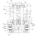
図1は、本発明に係る真空ポンプの第1の実施形態を示す縦断面図である。図1に示すように、真空ポンプは、ポンプケーシング1と、ポンプケーシング1内に対向して配置された一対のロータ2,2と、一対のロータ2,2を回転駆動するモータ部10とを備えている。前記一対のロータ2,2は、ポンプケーシング1に固定された第一の軸受3,3と、ポンプケーシング1の開口端に設けられた軸受プレート4に支持された第二の軸受5,5とにより回転自在に支承されている。一対のロータ2,2の軸間距離Lは、第一の軸受3,3の位置と第二の軸受5,5の位置を規定することにより所定の寸法に設定されている。第一の軸受3,3の位置は、ポンプケーシング1に形成された円形孔からなる軸受支持部1a,1aにより規定され、第二の軸受5,5の位置は、軸受プレート4に形成された円形孔からなる軸受支持部4a,4aにより規定される。第二の軸受5,5は軸受プレート4に固定された軸受押さえ6により押さえられている。
Embodiments of a vacuum pump according to the present invention will be described below with reference to FIGS. 1 to 3, the same or corresponding components are denoted by the same reference numerals, and redundant description is omitted.
FIG. 1 is a longitudinal sectional view showing a first embodiment of a vacuum pump according to the present invention. As shown in FIG. 1, the vacuum pump includes a
図1に示すように、一対のロータ2,2は、軸部2A,2Aとスクリューネジ部2S,2Sとを一体化したスクリューロータから構成されている。すなわち、各ロータ2は、軸部2Aとスクリューネジ部2Sとを嵌合して一体化している。以下の説明においては、ロータ2をスクリューロータ2とも適宜称する。スクリューロータ2,2とポンプケーシング1の内面との間には流体流路1fpが形成され、この流体流路1fpの上流側端部に吸気口1spが設けられ、流体流路1fpの下流側端部に排気口1dpが設けられている。スクリューロータ2,2は、僅かなクリアランスを保って非接触で相互に反転し、吸気口1spから吸込まれた気体を排気口1dpに移送するようになっている。
As shown in FIG. 1, the pair of
モータ部10はマグネットカップリング型DCブラシレスモータから構成されている。一対のロータ2,2の軸部2A,2Aの吸気側の軸端には、それぞれ同一の構成を有する一対のマグネットロータ11,11が配置されており、DCブラシレスモータとしてスクリューロータ2,2を反転駆動すると共に、マグネットカップリングによりスクリューロータ2,2を互いに同期させて逆方向に回転させるようになっている。各マグネットロータ11は、磁性材のヨークの外周にリング形状のマグネットを周設している。本実施形態では、マグネットロータ11の外周上には着磁したマグネットが周設され、互いのマグネットロータ11,11の異磁極が引き合うように対向し、且つクリアランスを保って配置されている。なお、マグネットロータ11の極数は4,6,8・・・などの偶数である。
The
各マグネットロータ11の外周面の一部に近接して、鉄心12aと巻線12bからなる三相(U,V,W)のモータステータ12が配置されている。対をなす三相のモータステータ12,12は一対のマグネットロータ11,11どうしがマグネットカップリングする側とは回転軸に関して反対側に配置されている。これにより、マグネットロータ11,11が互いに吸引するマグネットカップリング力をマグネットロータ11とモータステータ鉄心12aに作用する吸引力でキャンセルすることができる。また、三相のモータステータ磁極は、マグネットロータ11の磁極数に対応し、マグネットロータ11の各極に磁界をかけるようにしている。三相の巻線12bに所要の直流電流を供給することで、任意の回転数で一対のロータ2,2を同期反転駆動することができる。
A three-phase (U, V, W)
本発明においては、ポンプケーシング1と、ロータ2のスクリューネジ部2Sと、軸受プレート4の材質を同一にしている。すなわち、一対のロータ2,2の軸間距離Lを規定する第一の軸受3,3を収めるポンプケーシング1と、一対のロータ2,2の軸間距離Lを規定する第二の軸受5,5を収める軸受プレート4と、一対のロータ2,2のスクリューネジ部2S,2Sとを同一の材質で、すなわちアルミニウム合金で形成している。
In the present invention, the
真空ポンプが運転により温度上昇するとポンプ各部が熱膨張するが、ロータ2のスクリューネジ部2Sとポンプケーシング1の材料を同一にしておくことで、スクリューネジ部2Sとポンプケーシング1はほぼ同量の熱膨張となり、真空ポンプの性能に非常に重要であるロータ2のスクリューネジ部2Sとポンプケーシング1の微小隙間の変化量を非常に小さくすることができる。
また、一対のスクリューロータ2,2の軸間距離Lを決める第一の軸受3,3と第二の軸受5,5とを収めたポンプケーシング1と軸受プレート4の材質を同一にしてあるため、ポンプケーシング1と軸受プレート4におけるそれぞれの軸間距離の熱膨張量がほぼ同じになり、スクリューロータ2とポンプケーシング1の接触を防止することができる。
When the temperature of the vacuum pump rises due to operation, each part of the pump thermally expands. However, by making the
Further, the material of the
次に、各部クリアランスおよび各部位の線膨張係数と、接触の可能性および真空ポンプの性能との関係について、図2を参照して説明する。
図2(a),(b),(c)は、図1に示す真空ポンプの各部クリアランスおよび各部位の線膨張係数の関係を示す図であり、図2(a)は真空ポンプの全体を示す縦断面図であり、図2(b)はポンプケーシング1と一対のロータ2のスクリューネジ部2Sとの関係を示す模式的な横断面図であり、図2(c)は図2(a)のII部の拡大図である。
Next, the relationship between the clearance of each part and the linear expansion coefficient of each part, the possibility of contact, and the performance of the vacuum pump will be described with reference to FIG.
2 (a), (b) and (c) are diagrams showing the relationship between the clearance of each part of the vacuum pump shown in FIG. 1 and the linear expansion coefficient of each part. FIG. 2 (a) shows the entire vacuum pump. 2 (b) is a schematic cross-sectional view showing the relationship between the
図2(a)〜(c)に示すように、各部クリアランスと各部位の線膨張係数は以下のとおりである。
<各部クリアランス>
・ポンプケーシングとスクリューロータの隙間:δ1
・スクリューロータ内外径間の隙間:δ2
・スクリューロータ軸方向間の隙間:δ3
<各部位の線膨張係数>
・ロータのスクリューネジ部:λr
・ポンプケーシング:λc
・軸受プレート:λbc
各部クリアランスおよび各部位の線膨張係数と、接触の可能性および真空ポンプの性能との関係は以下のとおりである。
・λc>λrのとき、δ1及びδ2が大きくなり、真空ポンプの性能低下となる。
・λr>λcのとき、δ1及びδ2が小さくなり、接触の可能性が高まる。
・λbc>λrのとき、δ2が大きくなり、真空ポンプの性能低下となる。
・λr>λbcのとき、δ2が小さくなり、接触の可能性が高まる。
・λbc>λcのとき、A部の隙間狭くなり、接触の可能性が高まる。
・λc>λbcのとき、A部の隙間広くなり、真空ポンプの性能低下となる。
As shown in FIGS. 2A to 2C, the clearance of each part and the linear expansion coefficient of each part are as follows.
<Each part clearance>
・ Gap between pump casing and screw rotor: δ1
・ Gap between screw rotor inner and outer diameter: δ2
・ Gap between screw rotor shafts: δ3
<Linear expansion coefficient of each part>
-Rotor screw thread: λr
・ Pump casing: λc
・ Bearing plate: λbc
The relationship between the clearance of each part and the linear expansion coefficient of each part, the possibility of contact and the performance of the vacuum pump is as follows.
When λc> λr, δ1 and δ2 increase and the performance of the vacuum pump decreases.
When λr> λc, δ1 and δ2 become smaller and the possibility of contact increases.
When λbc> λr, δ2 increases and the performance of the vacuum pump decreases.
When λr> λbc, δ2 decreases and the possibility of contact increases.
・ When λbc> λc, the gap in the A portion becomes narrower and the possibility of contact increases.
・ When λc> λbc, the gap in the A portion becomes wider and the performance of the vacuum pump decreases.
上記各部位の材質としてはアルミニウムもしくはアルミニウム合金が好適である。これらは、線膨張係数が23×10−6/℃と大きいものの、比重が2.8と小さく、軽量化が図れること、熱伝導率が約150W/m・Kと大きく、ポンプの温度分布の均一化が図れるなどのメリットがある。
上記各部位の材質は樹脂でもよい。例えばPPS樹脂(比重:1.3〜1.8、線膨張係数:26〜69×10−6/℃)、PEEK樹脂(比重:1.3〜1.8、線膨張係数:47×10−6/℃)など。
Aluminum or aluminum alloy is suitable as the material for each of the above parts. These have a large linear expansion coefficient of 23 × 10 −6 / ° C., but the specific gravity is as small as 2.8, the weight can be reduced, the thermal conductivity is as large as about 150 W / m · K, and the temperature distribution of the pump There are merits such as uniformity.
The material of each of the above parts may be a resin. For example, PPS resin (specific gravity: 1.3 to 1.8, linear expansion coefficient: 26 to 69 × 10 −6 / ° C.), PEEK resin (specific gravity: 1.3 to 1.8, linear expansion coefficient: 47 × 10 − 6 / ° C).
次に、一対のロータ2,2の軸間距離Lを規定する第一の軸受3,3を収めるポンプケーシング1と、一対のロータ2,2の軸間距離Lを規定する第二の軸受5,5を収める軸受プレート4の構成について図1を参照して説明する。
図1に示すように、ポンプケーシング1は、その内部の最深部に一対のロータ2,2の軸間距離を決める要素の一つである第一の軸受3,3を配置している。ポンプケーシング1の位置決めは、一対のロータ2,2の軸間距離を決めるもう一つの要素である第二の軸受5,5を配置した軸受プレート4に対し行われるのが最適である。その方法として、平行ピンもしくはテーパーピンを2個用いる方法がある。ポンプケーシング1と軸受プレート4のそれぞれに同一のX、Y座標位置にピンを挿入する穴を設け、2部品を位置決めする方法である。また、ポンプケーシング1の内径とロータ2の外径の隙間も考える必要がある。2軸分あるケーシング内径とロータ外径は、回転周方向の隙間のばらつきを小さくするため、両軸ともできるだけ同心が得られていることが望ましい。そのため、ピンの座標は、ポンプケーシング1の内径の芯、また軸受プレート4の芯に対しての厳しい寸法公差が要求される。
Next, the
As shown in FIG. 1, the
それに対し、ポンプケーシング1の位置決めを、第二の軸受5,5を収納する軸受プレート4に対して直接に焼嵌めもしくは圧入にて行なうことは、ケーシング内に2軸分ある第一の軸受3,3の同心及び軸間を安定させ易くなる。例えば、ケーシング側で説明すると、軸受を収めるケーシングの内径加工(ここに軸受の外径が収まる)と、軸受プレートと焼嵌めもしくは圧入するケーシングの内径加工は同時加工でき、ピンでの位置決めに対し非常に高い精度の芯出しが可能である。これは軸受プレート側も同様である。
On the other hand, the positioning of the
すなわち、図1において太い点線で示すように第一の軸受3を収めるポンプケーシング1の軸受支持部1aの内径加工と、図1において太い実線で示すように軸受プレート4と焼嵌めもしくは圧入する部分であるポンプケーシング1の内径加工とは、同時加工することにより、ピンでの位置決めに対し非常に高い精度の芯出しが可能である。また、図1において太い点線で示すように第二の軸受5を収める軸受プレート4の軸受支持部4aの内径加工と、図1において太い実線で示すようにポンプケーシング1と焼嵌めもしくは圧入する部分である軸受プレート4の外径加工とは、同時加工することにより、ピンでの位置決めに対し非常に高い精度の芯出しが可能である。
That is, the inner diameter processing of the
図3は、図1の変形例を示す図である。図3に示す例においては、軸受プレート側のポンプケーシングとの位置決めを、軸受に対し同心で配置された別部品である軸受押さえ6に対し行う構造になっている。すなわち、図3において太い実線で示すように、ポンプケーシング1の内径と軸受押さえ6の外径とを嵌合することにより、ポンプケーシング1の位置決めを行っている。この場合、ポンプケーシング1の着脱を考えると、ポンプケーシング1と軸受押さえ6の線膨張係数に差を持たせておくと、すなわち、ポンプケーシング1>軸受押さえ6にしておけば、温度調整により着脱が安易に行える。例えば、軸受押さえの材質を、アルミニウムもしくはアルミニウム合金よりも線膨張係数の小さいステンレス合金(線膨張係数:10〜17×10−6/℃)などにすれば、ポンプケーシング1の嵌合位置の内径よりも軸受押さえ6の嵌合位置の外径を若干大きく製作し、焼嵌めにより締結しても、分解の際、温度を上昇させ、嵌合部に隙間を形成することで容易に分解することができる。
FIG. 3 is a diagram showing a modification of FIG. In the example shown in FIG. 3, the bearing
ポンプケーシング1と軸受プレート4の嵌合部は、両部品を同一材料で製作した場合、その分解の際に嵌合部での摺動が発生する。このとき、ケーシング内径及び軸受プレート外径の表面硬度が小さいと表面が削られてしまい、何度かの分解にて、嵌合隙間が変化してしまう。表面の削れが進行すると嵌合代がなくなり緩んでしまう。そのため、それぞれの部品には硬度を上げる表面処理を施しておくことが望ましい。以下に表面処理の候補とそのビッカース硬度を示す。
・硬質アルマイト:Hv200から400
・Niメッキ:Hv500から1000
・セラミックスメッキ:Hv1000から1500
・DLC(ダイヤモンドライクカーボン):Hv1500〜3000
ポンプケーシング1を別材質の軸受押さえ6に嵌合する場合は、軸受プレート4の表面処理の実施は任意である。また、ケーシング内径部は特にスクリューロータと微小隙間を形成しているので、傷などが付き難くしておくことが好ましく、したがって、ケーシング内径部への上記表面処理の施工は重要である。
When the parts of the
Hard anodized: Hv200 to 400
・ Ni plating: Hv500 to 1000
・ Ceramics plating: Hv1000 to 1500
DLC (Diamond Like Carbon): Hv 1500-3000
When the
これまで本発明の実施形態について説明したが、本発明は上述の実施形態に限定されず、その技術思想の範囲内において、種々の異なる形態で実施されてよいことは勿論である。 Although the embodiment of the present invention has been described so far, the present invention is not limited to the above-described embodiment, and it is needless to say that the present invention may be implemented in various different forms within the scope of the technical idea.
1 ポンプケーシング
1a 軸受支持部
2 ロータ,スクリューロータ
2A 軸部
2S スクリューネジ部
3 第一の軸受
4 軸受プレート
4a 軸受支持部
5 第二の軸受
6 軸受押さえ
10 モータ部
11 モータロータ
12 モータステータ
DESCRIPTION OF
Claims (6)
前記ケーシングと、前記ロータのスクリュー部と、前記一対のロータの軸間距離を規定する第二の軸受を収める軸受プレートの材質が同一であり、
前記一対のロータの軸間距離を規定する第二の軸受に対し同心に前記軸受プレートに締結されている軸受押さえを設け、前記ケーシングと前記軸受押さえとを焼嵌めもしくは圧入にて嵌合し、
前記ケーシングと前記軸受押さえの線膨張係数に差を持たせるようにしたことを特徴とする真空ポンプ。 A vacuum pump provided with a pair of rotors arranged opposite to each other, a casing for storing a first bearing that has an intake / exhaust port and defines an inter-axis distance between the pair of rotors, and a motor unit that rotationally drives the rotor Because
And the casing, and the screw portion of the rotor, Ri material identical der second bearing plate accommodating the bearing defining a distance between the axes of the pair of rotors,
A bearing retainer fastened to the bearing plate concentrically with respect to a second bearing that defines the inter-axis distance of the pair of rotors, and the casing and the bearing retainer are fitted by shrink fitting or press fitting,
A vacuum pump characterized by having a difference in linear expansion coefficient between the casing and the bearing retainer .
Priority Applications (1)
| Application Number | Priority Date | Filing Date | Title |
|---|---|---|---|
| JP2013036784A JP6091925B2 (en) | 2013-02-27 | 2013-02-27 | Vacuum pump |
Applications Claiming Priority (1)
| Application Number | Priority Date | Filing Date | Title |
|---|---|---|---|
| JP2013036784A JP6091925B2 (en) | 2013-02-27 | 2013-02-27 | Vacuum pump |
Publications (2)
| Publication Number | Publication Date |
|---|---|
| JP2014163340A JP2014163340A (en) | 2014-09-08 |
| JP6091925B2 true JP6091925B2 (en) | 2017-03-08 |
Family
ID=51614169
Family Applications (1)
| Application Number | Title | Priority Date | Filing Date |
|---|---|---|---|
| JP2013036784A Active JP6091925B2 (en) | 2013-02-27 | 2013-02-27 | Vacuum pump |
Country Status (1)
| Country | Link |
|---|---|
| JP (1) | JP6091925B2 (en) |
Families Citing this family (1)
| Publication number | Priority date | Publication date | Assignee | Title |
|---|---|---|---|---|
| JP7000914B2 (en) | 2018-02-26 | 2022-01-19 | トヨタ自動車株式会社 | Hydrogen pump |
Family Cites Families (5)
| Publication number | Priority date | Publication date | Assignee | Title |
|---|---|---|---|---|
| JPH02153290A (en) * | 1988-08-08 | 1990-06-12 | Nippon Piston Ring Co Ltd | Vacuum pump for priming |
| JP2006112389A (en) * | 2004-10-18 | 2006-04-27 | Denso Corp | Gas compressor |
| JP2009092042A (en) * | 2007-10-11 | 2009-04-30 | Nabtesco Corp | Bearing protection mechanism for rotary rotor pump |
| JP2009243280A (en) * | 2008-03-28 | 2009-10-22 | Hokuetsu Kogyo Co Ltd | Surface treatment method for casing for screw fluid machine, and casing for screw fluid machine |
| JP2010127119A (en) * | 2008-11-25 | 2010-06-10 | Ebara Corp | Dry vacuum pump unit |
-
2013
- 2013-02-27 JP JP2013036784A patent/JP6091925B2/en active Active
Also Published As
| Publication number | Publication date |
|---|---|
| JP2014163340A (en) | 2014-09-08 |
Similar Documents
| Publication | Publication Date | Title |
|---|---|---|
| AU2013348004B2 (en) | Air bearing for use as seal | |
| JP6079052B2 (en) | Vacuum pump | |
| JP2003042078A (en) | Scroll type compressor | |
| JP6694895B2 (en) | Machines with air compressors or liquid pumps | |
| JP7108377B2 (en) | Vacuum pumps, rotating parts of vacuum pumps, and unbalance correction methods | |
| JP6091925B2 (en) | Vacuum pump | |
| US7388308B2 (en) | Spindle device | |
| JP6225762B2 (en) | Turbo compressor | |
| JP2019110645A (en) | Rotary machine | |
| WO2018142964A1 (en) | Scroll compressor | |
| JP2014169663A (en) | Vacuum pump | |
| JP2007291878A (en) | Scroll type fluid machine | |
| TW201837321A (en) | Rotating machine and rotors for use therein | |
| CN107061315B (en) | Molecular pump | |
| JP2015113787A (en) | Scroll type fluid machine | |
| JP7142025B2 (en) | Electric motor assembly including pressure dam bearings | |
| JP6734296B2 (en) | Air compressor or liquid pump | |
| CN113286947A (en) | Pump with bearing lubrication system | |
| JP2017137845A (en) | Screw compressor and assembling method thereof | |
| JP4732833B2 (en) | Screw rotor and vacuum pump | |
| TW202225563A (en) | Dry vacuum pump | |
| JP2000220640A (en) | Motor and turbo-molecular pump | |
| JP2014134168A (en) | Vacuum pump | |
| JP2009236063A (en) | Pump device | |
| JP2017203438A (en) | Pump device and liner ring |
Legal Events
| Date | Code | Title | Description |
|---|---|---|---|
| A621 | Written request for application examination |
Free format text: JAPANESE INTERMEDIATE CODE: A621 Effective date: 20151209 |
|
| A131 | Notification of reasons for refusal |
Free format text: JAPANESE INTERMEDIATE CODE: A131 Effective date: 20160823 |
|
| A977 | Report on retrieval |
Free format text: JAPANESE INTERMEDIATE CODE: A971007 Effective date: 20160825 |
|
| A521 | Request for written amendment filed |
Free format text: JAPANESE INTERMEDIATE CODE: A523 Effective date: 20161019 |
|
| TRDD | Decision of grant or rejection written | ||
| A01 | Written decision to grant a patent or to grant a registration (utility model) |
Free format text: JAPANESE INTERMEDIATE CODE: A01 Effective date: 20170131 |
|
| A61 | First payment of annual fees (during grant procedure) |
Free format text: JAPANESE INTERMEDIATE CODE: A61 Effective date: 20170208 |
|
| R150 | Certificate of patent or registration of utility model |
Ref document number: 6091925 Country of ref document: JP Free format text: JAPANESE INTERMEDIATE CODE: R150 |
|
| R250 | Receipt of annual fees |
Free format text: JAPANESE INTERMEDIATE CODE: R250 |
|
| R250 | Receipt of annual fees |
Free format text: JAPANESE INTERMEDIATE CODE: R250 |
|
| R250 | Receipt of annual fees |
Free format text: JAPANESE INTERMEDIATE CODE: R250 |
|
| R250 | Receipt of annual fees |
Free format text: JAPANESE INTERMEDIATE CODE: R250 |
|
| R250 | Receipt of annual fees |
Free format text: JAPANESE INTERMEDIATE CODE: R250 |
|
| R250 | Receipt of annual fees |
Free format text: JAPANESE INTERMEDIATE CODE: R250 |
|
| R250 | Receipt of annual fees |
Free format text: JAPANESE INTERMEDIATE CODE: R250 |