JP6107639B2 - 電線排出装置 - Google Patents
電線排出装置 Download PDFInfo
- Publication number
- JP6107639B2 JP6107639B2 JP2013261221A JP2013261221A JP6107639B2 JP 6107639 B2 JP6107639 B2 JP 6107639B2 JP 2013261221 A JP2013261221 A JP 2013261221A JP 2013261221 A JP2013261221 A JP 2013261221A JP 6107639 B2 JP6107639 B2 JP 6107639B2
- Authority
- JP
- Japan
- Prior art keywords
- electric wire
- bar
- wire holding
- holding
- wire
- Prior art date
- Legal status (The legal status is an assumption and is not a legal conclusion. Google has not performed a legal analysis and makes no representation as to the accuracy of the status listed.)
- Active
Links
- 230000007246 mechanism Effects 0.000 claims description 91
- 238000007599 discharging Methods 0.000 claims description 22
- 230000001105 regulatory effect Effects 0.000 claims description 2
- 238000005520 cutting process Methods 0.000 description 40
- 238000002788 crimping Methods 0.000 description 20
- 210000000078 claw Anatomy 0.000 description 17
- 238000000034 method Methods 0.000 description 10
- 230000002265 prevention Effects 0.000 description 9
- 238000011143 downstream manufacturing Methods 0.000 description 8
- 238000004519 manufacturing process Methods 0.000 description 8
- 238000003825 pressing Methods 0.000 description 7
- 238000000605 extraction Methods 0.000 description 6
- 238000012423 maintenance Methods 0.000 description 5
- 230000007423 decrease Effects 0.000 description 2
- 239000002390 adhesive tape Substances 0.000 description 1
- 238000013459 approach Methods 0.000 description 1
- 238000005452 bending Methods 0.000 description 1
- 239000011248 coating agent Substances 0.000 description 1
- 238000000576 coating method Methods 0.000 description 1
- 238000003795 desorption Methods 0.000 description 1
- 238000010586 diagram Methods 0.000 description 1
- 230000000694 effects Effects 0.000 description 1
- 230000003028 elevating effect Effects 0.000 description 1
- 238000003780 insertion Methods 0.000 description 1
- 230000037431 insertion Effects 0.000 description 1
- 238000005259 measurement Methods 0.000 description 1
- 239000002184 metal Substances 0.000 description 1
- 230000002093 peripheral effect Effects 0.000 description 1
- 238000012545 processing Methods 0.000 description 1
- 238000000926 separation method Methods 0.000 description 1
- 230000007723 transport mechanism Effects 0.000 description 1
Images


Classifications
-
- H—ELECTRICITY
- H01—ELECTRIC ELEMENTS
- H01R—ELECTRICALLY-CONDUCTIVE CONNECTIONS; STRUCTURAL ASSOCIATIONS OF A PLURALITY OF MUTUALLY-INSULATED ELECTRICAL CONNECTING ELEMENTS; COUPLING DEVICES; CURRENT COLLECTORS
- H01R43/00—Apparatus or processes specially adapted for manufacturing, assembling, maintaining, or repairing of line connectors or current collectors or for joining electric conductors
- H01R43/28—Apparatus or processes specially adapted for manufacturing, assembling, maintaining, or repairing of line connectors or current collectors or for joining electric conductors for wire processing before connecting to contact members, not provided for in groups H01R43/02 - H01R43/26
-
- H—ELECTRICITY
- H01—ELECTRIC ELEMENTS
- H01R—ELECTRICALLY-CONDUCTIVE CONNECTIONS; STRUCTURAL ASSOCIATIONS OF A PLURALITY OF MUTUALLY-INSULATED ELECTRICAL CONNECTING ELEMENTS; COUPLING DEVICES; CURRENT COLLECTORS
- H01R43/00—Apparatus or processes specially adapted for manufacturing, assembling, maintaining, or repairing of line connectors or current collectors or for joining electric conductors
- H01R43/04—Apparatus or processes specially adapted for manufacturing, assembling, maintaining, or repairing of line connectors or current collectors or for joining electric conductors for forming connections by deformation, e.g. crimping tool
- H01R43/048—Crimping apparatus or processes
- H01R43/052—Crimping apparatus or processes with wire-feeding mechanism
Landscapes
- Engineering & Computer Science (AREA)
- Manufacturing & Machinery (AREA)
- Processing Of Terminals (AREA)
- Manufacturing Of Electrical Connectors (AREA)
Description
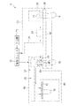
まず、切圧セット装置1の全体構成について説明する。図1は、切圧セット装置1の全体構成を示す説明図である。この切圧セット装置1は、切圧機構部22で処理された端子付電線18を電線排出装置30で処理するものであり、上記切圧機構部22で電線の長尺切断及び端子圧着を行い、電線排出装置30でその端子付電線18の端部を電線保持バー10に順次セットするとともに電線保持バー10ごと外部に取り出せるように構成されている。
次に、電線排出装置30について説明する。図2は、実施形態に係る電線排出装置30を示す説明図である。
このように構成された切圧セット装置1及び電線排出装置30の全体動作について説明する。
以上のように構成された電線排出装置30によると、切断及び端子圧着された端子付電線18の端部が、電線保持バー10の各電線保持部14に並列状にセットしたものを得ることができる。このため、下流工程での作業利便性を向上させることができると共に、電線や端子への傷付き、破損等を防止することができる。
14 電線保持部
18 端子付電線
22 切圧機構部
30 電線排出装置
32 電線端部保持セット部
33 電線端部回転部
36 電線端部搬送セット部
40 バー供給機構部
42 ガイド部
44 バー端部支持機構部
46 絡み防止シート部
50,52,55 バー支持部
60 移動機構部
70 制御ユニット
RP 電線受取位置
TP 取出位置
Claims (5)
- 複数の電線保持部が並列状に設けられた電線保持バーを支持可能なバー支持部2つと、
前記バー支持部に支持された前記電線保持バーの前記複数の電線保持部に電線を順次セットする電線端部保持セット部と、
前記電線端部保持セット部からの電線受取位置と前記電線保持バーの取出位置との間で2つの前記バー支持部をそれぞれ往復移動させる移動機構部と、
を備え、
2つの前記バー支持部に対する前記取出位置が、前記電線保持バーの延在方向に直交する方向に沿って、前記電線受取位置を挟んで異なっている、電線排出装置。 - 請求項1に記載の電線排出装置であって、
前記移動機構部は、2つの前記バー支持部が一定の間隔を有した状態で往復移動可能となるように、2つの前記バー支持部を同じ駆動源で一体的に移動させる、電線排出装置。 - 請求項1又は請求項2に記載の電線排出装置であって、
前記バー支持部に支持された前記電線保持バーの下方に位置する部分に絡み防止シート部が設けられている、電線排出装置。 - 請求項1〜請求項3のいずれか1項に記載の電線排出装置であって、
前記バー支持部は前記電線保持バーの延在方向における一方側端部を支持し、
前記バー支持部に支持された前記電線保持バーが前記電線受取位置に位置する状態で水平となるように、前記バー支持部の移動の際に前記バー支持部に支持された前記電線保持バーの延在方向における他方側端部の高さを規制可能なガイド部をさらに備える、電線排出装置。 - 請求項4に記載の電線排出装置であって、
前記バー支持部に支持された前記電線保持バーが前記電線受取位置に位置する状態で、前記電線保持バーの延在方向における前記他方側端部を前記一方側端部に向けて押さえつけることができるバー端部支持機構部をさらに備える、電線排出装置。
Priority Applications (7)
| Application Number | Priority Date | Filing Date | Title |
|---|---|---|---|
| JP2013261221A JP6107639B2 (ja) | 2013-12-18 | 2013-12-18 | 電線排出装置 |
| CN201480070029.5A CN105849824A (zh) | 2013-12-18 | 2014-12-03 | 电线排出装置 |
| KR1020167015482A KR20160085852A (ko) | 2013-12-18 | 2014-12-03 | 전선 배출 장치 |
| US15/100,485 US20160301178A1 (en) | 2013-12-18 | 2014-12-03 | Wire discharge device |
| EP14872453.7A EP3086329A4 (en) | 2013-12-18 | 2014-12-03 | Wire ejection device |
| PCT/JP2014/081978 WO2015093292A1 (ja) | 2013-12-18 | 2014-12-03 | 電線排出装置 |
| TW103142374A TWI559337B (zh) | 2013-12-18 | 2014-12-05 | Wire discharge device |
Applications Claiming Priority (1)
| Application Number | Priority Date | Filing Date | Title |
|---|---|---|---|
| JP2013261221A JP6107639B2 (ja) | 2013-12-18 | 2013-12-18 | 電線排出装置 |
Publications (2)
| Publication Number | Publication Date |
|---|---|
| JP2015118793A JP2015118793A (ja) | 2015-06-25 |
| JP6107639B2 true JP6107639B2 (ja) | 2017-04-05 |
Family
ID=53402641
Family Applications (1)
| Application Number | Title | Priority Date | Filing Date |
|---|---|---|---|
| JP2013261221A Active JP6107639B2 (ja) | 2013-12-18 | 2013-12-18 | 電線排出装置 |
Country Status (7)
| Country | Link |
|---|---|
| US (1) | US20160301178A1 (ja) |
| EP (1) | EP3086329A4 (ja) |
| JP (1) | JP6107639B2 (ja) |
| KR (1) | KR20160085852A (ja) |
| CN (1) | CN105849824A (ja) |
| TW (1) | TWI559337B (ja) |
| WO (1) | WO2015093292A1 (ja) |
Families Citing this family (4)
| Publication number | Priority date | Publication date | Assignee | Title |
|---|---|---|---|---|
| JP2017117609A (ja) * | 2015-12-24 | 2017-06-29 | 住友電装株式会社 | 電線排出装置 |
| CN107492425B (zh) * | 2017-08-13 | 2019-04-19 | 新昌县管富机械有限公司 | 一种废旧电缆剥皮回收装置 |
| CN109449721B (zh) * | 2018-11-05 | 2019-11-05 | 大庆市华禹石油机械制造有限公司 | 一种伺服电动机导线排布装置 |
| KR102105268B1 (ko) * | 2019-09-20 | 2020-04-27 | 이준열 | 케이블 라벨 부착 장치 |
Family Cites Families (18)
| Publication number | Priority date | Publication date | Assignee | Title |
|---|---|---|---|---|
| US5412933A (en) * | 1992-09-17 | 1995-05-09 | Joel D. Mallett | Automatic link forming apparatus |
| JP3632937B2 (ja) | 1996-05-20 | 2005-03-30 | 矢崎総業株式会社 | ハーネス製造方法と圧接機及びコネクタ保持竿並びに圧接装置 |
| JP3892919B2 (ja) * | 1996-10-03 | 2007-03-14 | 矢崎総業株式会社 | ワイヤハーネスの製造方法及び製造装置 |
| JP4327335B2 (ja) * | 2000-06-23 | 2009-09-09 | 株式会社アドバンテスト | コンタクトアームおよびこれを用いた電子部品試験装置 |
| US6961996B2 (en) * | 2001-04-10 | 2005-11-08 | Komax Holding Ag | Method for installing cable ends in plug housings |
| DE50214847D1 (de) * | 2001-10-31 | 2011-02-17 | Komax Holding Ag | Handhabungsvorrichtung für Drahtleitung, Einführungsmaschine und Einführungsverfahren mit einer solchen Handhabungsvorrichtung |
| JP4063127B2 (ja) * | 2003-04-10 | 2008-03-19 | 住友電装株式会社 | ワイヤーハーネスの自動生産システム |
| JP3982480B2 (ja) | 2003-10-31 | 2007-09-26 | 住友電装株式会社 | マルチ圧着装置及び端子供給モジュール |
| EP1653576B1 (de) * | 2004-11-02 | 2008-08-06 | komax Holding AG | Kabelspeicher |
| JP5194772B2 (ja) * | 2007-12-21 | 2013-05-08 | 住友電装株式会社 | 切圧セット装置及びワイヤーハーネスの製造方法 |
| JP2009152105A (ja) * | 2007-12-21 | 2009-07-09 | Sumitomo Wiring Syst Ltd | 電線セット揃え装置及びサブアッシーの製造方法 |
| JP5287108B2 (ja) * | 2008-10-01 | 2013-09-11 | 住友電装株式会社 | 電線接続集合体製造支援装置及び電線接続集合体の製造方法 |
| US8113557B2 (en) * | 2009-05-19 | 2012-02-14 | Artos Engineering Company | Wire gripper jaw drive |
| JP4985713B2 (ja) * | 2009-06-10 | 2012-07-25 | 住友電装株式会社 | 電線保持バー搬送装置及び電線セット製造方法 |
| WO2012120631A1 (ja) * | 2011-03-08 | 2012-09-13 | 日本オートマチックマシン株式会社 | ワイヤーハーネスの製造装置及び製造方法 |
| JP5842631B2 (ja) * | 2012-01-25 | 2016-01-13 | 住友電装株式会社 | 電線保持バー搬送装置 |
| JP5817576B2 (ja) * | 2012-02-09 | 2015-11-18 | 住友電装株式会社 | 電線移載装置 |
| CN202805184U (zh) * | 2012-09-06 | 2013-03-20 | 东莞市五株电子科技有限公司 | 机械手取放设备 |
-
2013
- 2013-12-18 JP JP2013261221A patent/JP6107639B2/ja active Active
-
2014
- 2014-12-03 WO PCT/JP2014/081978 patent/WO2015093292A1/ja not_active Ceased
- 2014-12-03 KR KR1020167015482A patent/KR20160085852A/ko not_active Abandoned
- 2014-12-03 CN CN201480070029.5A patent/CN105849824A/zh active Pending
- 2014-12-03 EP EP14872453.7A patent/EP3086329A4/en not_active Withdrawn
- 2014-12-03 US US15/100,485 patent/US20160301178A1/en not_active Abandoned
- 2014-12-05 TW TW103142374A patent/TWI559337B/zh not_active IP Right Cessation
Also Published As
| Publication number | Publication date |
|---|---|
| TW201535422A (zh) | 2015-09-16 |
| CN105849824A (zh) | 2016-08-10 |
| KR20160085852A (ko) | 2016-07-18 |
| TWI559337B (zh) | 2016-11-21 |
| JP2015118793A (ja) | 2015-06-25 |
| WO2015093292A1 (ja) | 2015-06-25 |
| EP3086329A1 (en) | 2016-10-26 |
| US20160301178A1 (en) | 2016-10-13 |
| EP3086329A4 (en) | 2017-01-04 |
Similar Documents
| Publication | Publication Date | Title |
|---|---|---|
| JP5194772B2 (ja) | 切圧セット装置及びワイヤーハーネスの製造方法 | |
| JP6107639B2 (ja) | 電線排出装置 | |
| JP5817576B2 (ja) | 電線移載装置 | |
| US20200245471A1 (en) | Lead component mounting machine and lead component mounting method | |
| JP4985713B2 (ja) | 電線保持バー搬送装置及び電線セット製造方法 | |
| KR20180098295A (ko) | 파권 장치 | |
| CN106605274B (zh) | 线束制造装置和线束制造方法 | |
| JP2009152105A (ja) | 電線セット揃え装置及びサブアッシーの製造方法 | |
| CN108233148B (zh) | 多种端子供给装置、方法及复式压接装置 | |
| JP5317106B2 (ja) | コイル成形装置及びコイル成形方法 | |
| CN105405640A (zh) | 一种粗线绕线机 | |
| CN111362051A (zh) | 智能线束机的线缆移送装置 | |
| JP6457804B2 (ja) | 端子圧着治具セット補助装置および端子圧着システム | |
| KR101509182B1 (ko) | 철근의 나사선 가공 장치 | |
| JP2015122246A (ja) | 端子送り装置 | |
| JP2003223822A (ja) | ワイヤーハーネスの製造装置 | |
| JP5776582B2 (ja) | 端子成形金型装置の交換装置 | |
| JP5548802B2 (ja) | コイル成形装置 | |
| JP4649449B2 (ja) | 電線加工機における電線測長装置 | |
| JP5768749B2 (ja) | 電線処理装置 | |
| CN107257708B (zh) | 用于操纵卷绕的线束的装置和方法 | |
| WO2017110489A1 (ja) | 電線排出装置 | |
| JPH0910835A (ja) | スリッタの巻取機への鋼板誘導装置 |
Legal Events
| Date | Code | Title | Description |
|---|---|---|---|
| A621 | Written request for application examination |
Free format text: JAPANESE INTERMEDIATE CODE: A621 Effective date: 20160127 |
|
| A131 | Notification of reasons for refusal |
Free format text: JAPANESE INTERMEDIATE CODE: A131 Effective date: 20170117 |
|
| A521 | Request for written amendment filed |
Free format text: JAPANESE INTERMEDIATE CODE: A523 Effective date: 20170124 |
|
| TRDD | Decision of grant or rejection written | ||
| A01 | Written decision to grant a patent or to grant a registration (utility model) |
Free format text: JAPANESE INTERMEDIATE CODE: A01 Effective date: 20170207 |
|
| A61 | First payment of annual fees (during grant procedure) |
Free format text: JAPANESE INTERMEDIATE CODE: A61 Effective date: 20170220 |
|
| R150 | Certificate of patent or registration of utility model |
Ref document number: 6107639 Country of ref document: JP Free format text: JAPANESE INTERMEDIATE CODE: R150 |
|
| R250 | Receipt of annual fees |
Free format text: JAPANESE INTERMEDIATE CODE: R250 |