JP6165100B2 - タイロッド連結具 - Google Patents
タイロッド連結具 Download PDFInfo
- Publication number
- JP6165100B2 JP6165100B2 JP2014102933A JP2014102933A JP6165100B2 JP 6165100 B2 JP6165100 B2 JP 6165100B2 JP 2014102933 A JP2014102933 A JP 2014102933A JP 2014102933 A JP2014102933 A JP 2014102933A JP 6165100 B2 JP6165100 B2 JP 6165100B2
- Authority
- JP
- Japan
- Prior art keywords
- tie rod
- tie
- piston
- check valve
- orifice
- Prior art date
- Legal status (The legal status is an assumption and is not a legal conclusion. Google has not performed a legal analysis and makes no representation as to the accuracy of the status listed.)
- Expired - Fee Related
Links
- 238000003780 insertion Methods 0.000 claims description 24
- 230000037431 insertion Effects 0.000 claims description 24
- 230000008878 coupling Effects 0.000 claims description 8
- 238000010168 coupling process Methods 0.000 claims description 8
- 238000005859 coupling reaction Methods 0.000 claims description 8
- 239000004615 ingredient Substances 0.000 claims description 2
- 239000000463 material Substances 0.000 description 12
- 230000035939 shock Effects 0.000 description 6
- 238000004891 communication Methods 0.000 description 5
- 238000010276 construction Methods 0.000 description 5
- 230000008602 contraction Effects 0.000 description 5
- 230000006835 compression Effects 0.000 description 3
- 238000007906 compression Methods 0.000 description 3
- 238000009423 ventilation Methods 0.000 description 3
- 229910000975 Carbon steel Inorganic materials 0.000 description 2
- 239000010962 carbon steel Substances 0.000 description 2
- 230000002093 peripheral effect Effects 0.000 description 2
- 229910000831 Steel Inorganic materials 0.000 description 1
- 239000006096 absorbing agent Substances 0.000 description 1
- 230000000903 blocking effect Effects 0.000 description 1
- 239000004566 building material Substances 0.000 description 1
- 238000010586 diagram Methods 0.000 description 1
- 238000005516 engineering process Methods 0.000 description 1
- 238000009434 installation Methods 0.000 description 1
- 238000005259 measurement Methods 0.000 description 1
- 239000000203 mixture Substances 0.000 description 1
- 230000000149 penetrating effect Effects 0.000 description 1
- 229920000642 polymer Polymers 0.000 description 1
- 239000002861 polymer material Substances 0.000 description 1
- 239000010935 stainless steel Substances 0.000 description 1
- 229910001220 stainless steel Inorganic materials 0.000 description 1
- 239000010959 steel Substances 0.000 description 1
Images




Landscapes
- Joining Of Building Structures In Genera (AREA)
Description
タイロッドの一端側を挿入する挿入孔が設けられるタイロッド挿入壁を備え、内部に挿通されたタイロッドの先端側を受け入れる受入空間を有するシリンダケーシングと、
前記タイロッドの先端に設けられ、前記シリンダケーシングの内壁に沿って摺動可能なタイロッドピストンと、
前記タイロッドピストンに設けられ、前記受入空間内における前記タイロッドピストンの摺動によって生じる内圧差によって、前記タイロッドピストンの前記シリンダケーシングの内壁への押圧力を調整するチェックバルブユニットを有することを特徴とするタイロッド連結具を提供する。
一端が前記タイロッドピストンに連結され、他端が前記タイロッド挿入壁の内面に当接するように前記タイロッドを挿通するように設けられたコイルバネと、を有することを特徴とする、第1態様のタイロッド連結具を提供する。
前記摺動方向に交差する方向に移動可能前記バルブ収納空間に収納される制御バルブと、を備えることを特徴とする、第1から第3態様のいずれか1つのタイロッド連結具を提供する。
前記第2のバルブ収納空間に、内部で偏在して前記オリフィスの開通と遮断を切り替える制御ボールが収納されていることを特徴とする、第4態様のタイロッド連結具を提供する。
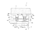
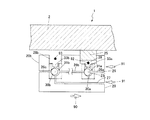
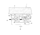
図1は、本発明のタイロッド用連結具の第1実施形態にかかる使用状態のタイロッド用ターンバックルの構成を示す一部断面図である。図2は、図1のタイロッド用ターンバックルの部分拡大分解斜視図である。図1及び図2では、タイロッド用ターンバックル1に加えて、タイロッド用ターンバックル1に接続されるタイロッド50も示している。
2 ケーシング本体
2a 受入空間
3 調整ボルト
4 コイルバネ
5 衝撃緩衝部材
6 順ネジ
7 逆ネジ
8 頭部
8a タイロッド挿入壁
8b スパナ掛け
9a 雄ネジ部
10 タイロッド挿入孔
11 貫通孔
20 タイロッドピストン
21 雌ネジ
22 チェックバルブユニット
23 第1のチェックバルブ
24 第2のチェックバルブ
25 ピストンリング
26 第1のオリフィス
27 第2のオリフィス
28a,28b ネジ孔
29a,29b流量調整ネジ
30a,30b 制御ボール
31a,31b バルブ収容空間
32a,32b バルブ蓋
50 タイロッド
51 先端
52 ネジ
53 ストッパー
54 雌ネジ
55 目盛り
60 ガセットプレート
61 ピン挿通孔
Claims (5)
- タイロッドを連結するためのタイロッド連結具であって、
タイロッドの一端側を挿入する挿入孔が設けられるタイロッド挿入壁を備え、内部に挿通されたタイロッドの先端側を受け入れる受入空間を有するシリンダケーシングと、
前記タイロッドの先端に設けられ、前記シリンダケーシングの内壁に沿って摺動可能なタイロッドピストンと、
前記タイロッドピストンに設けられ、前記受入空間内における前記タイロッドピストンの摺動によって生じる内圧差によって、前記タイロッドピストンの前記シリンダケーシングの内壁への押圧力を調整するチェックバルブユニットを有することを特徴とするタイロッド連結具。 - 前記シリンダケーシングは、前記タイロッドの一端側を挿入する挿入孔が設けられるタイロッド挿入壁を備え、
一端が前記タイロッドピストンに連結され、他端が前記タイロッド挿入壁の内面に当接するように前記タイロッドを挿通するように設けられたコイルバネと、を有することを特徴とする、請求項1に記載のタイロッド連結具。 - 前記シリンダケーシングは、前記受入空間が形成され、開口部分にネジ部が形成されたケーシング本体と、前記ケーシング本体のネジ部に螺合するネジ部と前記タイロッド挿入壁を形成する頭部を有する調整ボルトを有することを特徴とする、請求項2に記載のタイロッド連結具。
- 前記チェックバルブユニットは、前記タイロッドピストンの摺動方向に伸び、中間位置に設けられるバルブ収納空間を有するオリフィスと、
前記摺動方向に交差する方向に移動可能前記バルブ収納空間に収納される制御バルブと、を備えることを特徴とする、請求項1から3のいずれか1つに記載のタイロッド連結具。 - 前記チェックバルブユニットは、前記オリフィスに第2のバルブ収納空間を有し、
前記第2のバルブ収納空間に、内部で偏在して前記オリフィスの開通と遮断を切り替える制御ボールが収納されている第2のチェックバルブを有することを特徴とする、請求項4に記載のタイロッド連結具。
Priority Applications (1)
| Application Number | Priority Date | Filing Date | Title |
|---|---|---|---|
| JP2014102933A JP6165100B2 (ja) | 2014-05-19 | 2014-05-19 | タイロッド連結具 |
Applications Claiming Priority (1)
| Application Number | Priority Date | Filing Date | Title |
|---|---|---|---|
| JP2014102933A JP6165100B2 (ja) | 2014-05-19 | 2014-05-19 | タイロッド連結具 |
Publications (2)
| Publication Number | Publication Date |
|---|---|
| JP2015218490A JP2015218490A (ja) | 2015-12-07 |
| JP6165100B2 true JP6165100B2 (ja) | 2017-07-19 |
Family
ID=54778107
Family Applications (1)
| Application Number | Title | Priority Date | Filing Date |
|---|---|---|---|
| JP2014102933A Expired - Fee Related JP6165100B2 (ja) | 2014-05-19 | 2014-05-19 | タイロッド連結具 |
Country Status (1)
| Country | Link |
|---|---|
| JP (1) | JP6165100B2 (ja) |
Families Citing this family (1)
| Publication number | Priority date | Publication date | Assignee | Title |
|---|---|---|---|---|
| KR102135337B1 (ko) * | 2018-10-04 | 2020-07-21 | 주식회사 비엠이앤씨 | 내진 보강용 이력 댐퍼 |
Family Cites Families (8)
| Publication number | Priority date | Publication date | Assignee | Title |
|---|---|---|---|---|
| JPH0579524A (ja) * | 1991-09-24 | 1993-03-30 | Nissan Motor Co Ltd | シヨツクアブソーバ |
| JP3931289B2 (ja) * | 1999-08-25 | 2007-06-13 | カヤバ工業株式会社 | 制振装置 |
| JP3069686U (ja) * | 1999-12-16 | 2000-06-23 | 大栄工業株式会社 | 建物の免振装置 |
| JP2002070913A (ja) * | 2000-08-24 | 2002-03-08 | Showa Corp | 油圧緩衝器 |
| JP2003148545A (ja) * | 2001-11-07 | 2003-05-21 | Kozo Keikaku Engineering Inc | 油圧制振装置 |
| JP4050103B2 (ja) * | 2002-07-01 | 2008-02-20 | 日立機材株式会社 | 油圧式ダンパ |
| JP4182200B2 (ja) * | 2002-07-22 | 2008-11-19 | 日立機材株式会社 | 油圧式ダンパ |
| JP4565526B1 (ja) * | 2010-03-29 | 2010-10-20 | 竹四 竹内 | 制震筋交 |
-
2014
- 2014-05-19 JP JP2014102933A patent/JP6165100B2/ja not_active Expired - Fee Related
Also Published As
| Publication number | Publication date |
|---|---|
| JP2015218490A (ja) | 2015-12-07 |
Similar Documents
| Publication | Publication Date | Title |
|---|---|---|
| DE102009032897B4 (de) | Kolben-Zylinderaggregat | |
| EP2992158B1 (en) | Improvements in damper assemblies | |
| US10557513B2 (en) | Dampers | |
| US20140230645A1 (en) | Gas cylinder, in particular high-pressure gas cylinder | |
| EP2981796B1 (de) | Kraft-messvorrichtung | |
| US9677640B2 (en) | Damper assemblies | |
| RU2014136525A (ru) | Соединительный элемент | |
| JP2002031182A (ja) | ショックアブソーバ | |
| JP2013072469A (ja) | 油圧ダンパ及びその油量監視方法 | |
| JP6165100B2 (ja) | タイロッド連結具 | |
| JP7508687B2 (ja) | 家具ダンパ | |
| JP2017009485A (ja) | ストローク検出装置 | |
| CN107165967B (zh) | 缓冲装置 | |
| US10746251B2 (en) | Load damping assembly with gapping feature | |
| CN116249845B (zh) | 锁定系统 | |
| BR112019002717A2 (pt) | método para a produção de um conjunto de pistão e dispositivo de fluido hidráulico | |
| JP6192555B2 (ja) | タイロッド用連結具 | |
| EP2721307A1 (en) | Device for damping of a piston inside a cylinder housing | |
| JP2015148045A (ja) | タイロッド連結具及びタイロッドの張力測定方法 | |
| JP6770458B2 (ja) | 横置き型ダンパ | |
| US20100212488A1 (en) | Hydro-Pneumatic Cylinder with Controlled Stop Position | |
| ITBS20090193A1 (it) | Deceleratore idraulico | |
| JP2011133007A (ja) | 流体圧シリンダ | |
| JP5504416B2 (ja) | 油圧ダンパ | |
| JP7112852B2 (ja) | 調圧弁および油圧ダンパ |
Legal Events
| Date | Code | Title | Description |
|---|---|---|---|
| A621 | Written request for application examination |
Free format text: JAPANESE INTERMEDIATE CODE: A621 Effective date: 20170517 |
|
| A871 | Explanation of circumstances concerning accelerated examination |
Free format text: JAPANESE INTERMEDIATE CODE: A871 Effective date: 20170517 |
|
| A975 | Report on accelerated examination |
Free format text: JAPANESE INTERMEDIATE CODE: A971005 Effective date: 20170612 |
|
| TRDD | Decision of grant or rejection written | ||
| A01 | Written decision to grant a patent or to grant a registration (utility model) |
Free format text: JAPANESE INTERMEDIATE CODE: A01 Effective date: 20170620 |
|
| A61 | First payment of annual fees (during grant procedure) |
Free format text: JAPANESE INTERMEDIATE CODE: A61 Effective date: 20170620 |
|
| R150 | Certificate of patent or registration of utility model |
Ref document number: 6165100 Country of ref document: JP Free format text: JAPANESE INTERMEDIATE CODE: R150 |
|
| R250 | Receipt of annual fees |
Free format text: JAPANESE INTERMEDIATE CODE: R250 |
|
| LAPS | Cancellation because of no payment of annual fees |