JP6180748B2 - Sedimentation separation apparatus and sedimentation separation method for radioactive liquid waste - Google Patents
Sedimentation separation apparatus and sedimentation separation method for radioactive liquid waste Download PDFInfo
- Publication number
- JP6180748B2 JP6180748B2 JP2013021479A JP2013021479A JP6180748B2 JP 6180748 B2 JP6180748 B2 JP 6180748B2 JP 2013021479 A JP2013021479 A JP 2013021479A JP 2013021479 A JP2013021479 A JP 2013021479A JP 6180748 B2 JP6180748 B2 JP 6180748B2
- Authority
- JP
- Japan
- Prior art keywords
- waste liquid
- radioactive waste
- sedimentation
- separation tank
- radioactive
- Prior art date
- Legal status (The legal status is an assumption and is not a legal conclusion. Google has not performed a legal analysis and makes no representation as to the accuracy of the status listed.)
- Active
Links
Images



Classifications
-
- Y—GENERAL TAGGING OF NEW TECHNOLOGICAL DEVELOPMENTS; GENERAL TAGGING OF CROSS-SECTIONAL TECHNOLOGIES SPANNING OVER SEVERAL SECTIONS OF THE IPC; TECHNICAL SUBJECTS COVERED BY FORMER USPC CROSS-REFERENCE ART COLLECTIONS [XRACs] AND DIGESTS
- Y02—TECHNOLOGIES OR APPLICATIONS FOR MITIGATION OR ADAPTATION AGAINST CLIMATE CHANGE
- Y02E—REDUCTION OF GREENHOUSE GAS [GHG] EMISSIONS, RELATED TO ENERGY GENERATION, TRANSMISSION OR DISTRIBUTION
- Y02E30/00—Energy generation of nuclear origin
- Y02E30/30—Nuclear fission reactors
Landscapes
- Solid-Sorbent Or Filter-Aiding Compositions (AREA)
- Treatment Of Sludge (AREA)
Description
本発明は、例えば核燃料物質等の固体粒子を含む放射性廃液の沈降分離装置及び沈降分離方法に関する。 The present invention relates to a sedimentation separation apparatus and sedimentation separation method for radioactive liquid waste containing solid particles such as nuclear fuel materials.
大災害時に原子力プラントで炉心溶融事故が発生した場合、現状では溶融炉心は注水によって冷却されるが、その際、燃料棒から溶出したウラン(U)やプルトニウム(Pu)等の核燃料物質の一部は固体粒子となって冷却水中に沈殿する。このような炉心溶融事故が発生した原子炉を廃炉にする場合、建屋や格納容器内に貯溜した放射性廃液中の核燃料物質を含む固体粒子の処理が必要となる。これらの固体粒子は放射性廃液中に存在するため、減容および安全管理の観点から、例えば、沈降分離手段によって固液分離処理を行い、保管容器等に移され長期保管される。この沈殿分離法は、固体粒子と液体との密度差による固体粒子の重力沈降を利用する簡便な固液分離システムであるため、様々な分野で広く使われている(特許文献1)。 In the event of a core melting accident at a nuclear power plant during a major disaster, the molten core is currently cooled by water injection. At that time, some of the nuclear fuel materials such as uranium (U) and plutonium (Pu) eluted from the fuel rods. Becomes solid particles and precipitates in the cooling water. When a nuclear reactor in which such a core melting accident has occurred is to be decommissioned, it is necessary to treat solid particles containing nuclear fuel material in the radioactive liquid waste stored in the building or containment vessel. Since these solid particles are present in the radioactive liquid waste, from the viewpoint of volume reduction and safety management, for example, solid-liquid separation processing is performed by sedimentation separation means, and then transferred to a storage container or the like and stored for a long time. Since this precipitation separation method is a simple solid-liquid separation system that uses gravity sedimentation of solid particles due to the density difference between the solid particles and the liquid, it is widely used in various fields (Patent Document 1).
しかしながら、放射性廃液中に固体粒子状の核燃料物質が含まれる場合、固体粒子濃度によっては、処理時に臨界状態になる危険性がある。したがって、使用済核燃料物質を処理対象とする核燃料再処理施設では、処理工程で処理対象物が臨界状態になることを防止するために、厳重な臨界防止管理が必要となる。そのため、核燃料を析出回収する回収槽を臨界にならない間隔を有する平板状で形成することや多段階の沈降槽を設ける等の対策が講じられている(特許文献2、3)。
However, when the nuclear waste material in the form of solid particles is contained in the radioactive liquid waste, there is a risk of becoming a critical state during processing depending on the solid particle concentration. Accordingly, in a nuclear fuel reprocessing facility that uses spent nuclear fuel material as a processing target, strict criticality prevention management is required to prevent the processing target from becoming a critical state in the processing step. Therefore, measures such as forming a recovery tank for depositing and recovering nuclear fuel in a flat plate shape having a non-critical interval and providing a multi-stage sedimentation tank have been taken (
上述したように、特許文献2及び3に示された核燃料再処理施設では、核燃料を析出回収する回収槽を臨界にならない間隔を有する平板状で複数形成することや多段の沈降槽を設ける等の対策が講じられているが、放射性廃液中に固体粒子状の核燃料物質が含まれる場合は、放射性廃液の処理工程においても厳格な臨界防止対策が必要となる。
As described above, in the nuclear fuel reprocessing facilities shown in
したがって、これらの核燃料再処理施設における臨界防止手段を廃炉の際の放射性廃液の処理に用いることが考えられるが、これらの回収槽(沈殿槽)は容積が小さいため、大量の放射性廃液を短時間で処理することが困難であり、また、回収槽(沈殿槽)を多段に配置するために処理施設が大型化するとともに処理時間が長期化するという課題があった。 Therefore, it is conceivable to use the criticality prevention means in these nuclear fuel reprocessing facilities for the treatment of radioactive liquid waste at the time of decommissioning, but these collection tanks (sedimentation tanks) are small in volume, so that a large amount of radioactive liquid waste can be shortened. It is difficult to process in time, and there is a problem that the processing facility is enlarged and the processing time is prolonged because the collection tanks (sedimentation tanks) are arranged in multiple stages.
さらに、これらの回収槽(沈殿槽)を沈殿分離槽として用いる場合、その底面が平坦なため、放射性廃液中の固体粒子が回収槽(沈殿槽)の底部に不均一に沈殿堆積する可能性があり、臨界管理が困難になるという課題があった。 Furthermore, when these recovery tanks (precipitation tanks) are used as precipitation separation tanks, the bottom surface is flat, so there is a possibility that solid particles in the radioactive waste liquid will deposit and deposit unevenly at the bottom of the recovery tank (precipitation tank). There was a problem that criticality management became difficult.
本発明は上記課題を解決するためになされたもので、大容量の放射性廃液を短時間で処理可能するとともに、処理工程において臨界発生を確実に防止することができる放射性廃液の沈降分離装置及び沈降分離方法を提供することを目的とする。 The present invention has been made to solve the above-mentioned problems, and is capable of processing a large volume of radioactive waste liquid in a short time and can reliably prevent the occurrence of criticality in the processing step, and a sedimentation apparatus and sedimentation apparatus for radioactive waste liquid. An object is to provide a separation method.
上記目的を達成するために、本発明に係る放射性廃液の沈降分離装置は、下方が逆錐状に傾斜し内部に放射性廃液が注入される沈殿分離槽と、前記沈殿分離槽の上部に配置され複数の粒状の臨界抑止部材を前記沈殿分離槽内に投入する投入部と、を有し、前記粒状の臨界抑止部材の沈降速度は、前記放射性廃液中に含まれる核燃料物質の沈降速度と同等であることを特徴とする。
また、本発明に係る放射性廃液の沈降分離方法は、本発明に係る放射性廃液の沈殿分離装置を用いて放射性廃液を沈殿分離することを特徴とする。
In order to achieve the above object, a radioactive waste liquid sedimentation separation apparatus according to the present invention is disposed at a top of the precipitation separation tank, a precipitation separation tank in which the lower part is inclined in an inverted conical shape and into which radioactive waste liquid is injected. A plurality of granular critical deterrent members into the sedimentation tank, and the sedimentation rate of the granular critical deterrent members is equivalent to the sedimentation rate of the nuclear fuel material contained in the radioactive liquid waste It is characterized by being.
Moreover, the sedimentation method for radioactive liquid waste according to the present invention is characterized in that the radioactive liquid waste is separated by precipitation using the radioactive liquid waste sedimentation apparatus according to the present invention.
本発明によれば、ウランやプルトニウム等の臨界管理が必要な核燃料物質を含有する大容量の放射性廃液を短時間で処理することが可能となるとともに、処理工程における臨界発生を確実に防止することができる。 According to the present invention, it becomes possible to process a large volume of radioactive liquid waste containing nuclear fuel materials that require critical control such as uranium and plutonium in a short time, and reliably prevent the occurrence of criticality in the processing process. Can do.
以下、本発明に係る放射性廃液の沈降分離装置及び沈降分離方法の実施形態について、図面を参照して説明する。 DESCRIPTION OF EMBODIMENTS Hereinafter, embodiments of a radioactive waste liquid sedimentation separation apparatus and sedimentation separation method according to the present invention will be described with reference to the drawings.
[第1の実施形態]
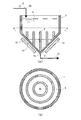
第1の実施形態に係る沈降分離装置について図1を参照して説明する。
(構成)
本実施形態に係る沈降分離装置は、基本的に逆錐状の沈降分離槽と、その底部に設けられた中性子吸収材からなる臨界抑止部材とから構成される。
[First Embodiment]
The sedimentation separator according to the first embodiment will be described with reference to FIG.
(Constitution)
The sedimentation separation apparatus according to this embodiment is basically composed of an inverted conical sedimentation separation tank and a critical suppression member made of a neutron absorber provided at the bottom thereof.
沈降分離槽1は、底部が下端部1bに向けて傾斜した例えば逆円錐形等からなる逆錐形状であり、傾斜面1aの傾斜角は注入される放射性廃液2中のスラッジ3が沈殿分離槽1の底部に偏在することなく安定した堆積部を形成するように安息角以上の角度に設定される。
The
臨界抑止部材5は、図1(a)、(b)に示すように、沈殿分離槽1の底部の中心位置とその同心状の位置に複数設けられている。この棒状及び円筒状の臨界抑止部材5の数、設置間隔、高さは、沈殿分離槽1の容量、放射性廃液2の処理量、核燃料物質の含有量等に応じて、臨界防止の観点から適宜に設定変更可能である。
As shown in FIGS. 1A and 1B, a plurality of
臨界抑止部材5は、熱中性子吸収断面積が大きい元素であるリチウム(Li)、ホウ素(B)、ロジウム(Rh)、カドミウム(Cd)、インジウム(In)、サマリウム(Sm)、ユーロピウム(Eu)、ガドリニウム(Gd)、ジスプロシウム(Dy)、エルビウム(Er)、ツリウム(Tm)、ハフニウム(Hf)、水銀(Hg)などの元素およびこれら元素の化合物、またはこれら元素およびその化合物を少なくとも1種類以上含む材料が用いられる。
The
この沈殿分離槽1には、ウランやプルトニウムなどの臨界管理が必要な核種を含む金属酸化物、水酸化物又は炭酸塩等の固形分(スラッジ)を含む放射性廃液2が供給配管20から注入されるが、この放射性廃液2には液媒として水やアルコール、TBP(リン酸トリブチル)等が適宜添加される。供給配管20を通して沈殿分離槽1に注入された放射性廃液2は沈降分離により底部にスラッジ3が堆積し、上部に上澄液4が貯溜される。
A
また、放射性廃液2から発生する中性子および放射線量を計測するために、沈殿分離槽1の下方外側に臨界管理用の臨界モニタ12及び放射線線量計13が設置される。
なお、沈降分離槽1を構成する構造材に上述した熱中性子吸収断面積の大きな中性子吸収材を含有させてもよい。
In addition, in order to measure neutrons and radiation dose generated from the radioactive
In addition, you may make the structural material which comprises the sedimentation-
(作用)
このように構成された沈降分離装置において、供給配管20を通して沈殿分離槽1に注入された放射性廃液2は、時間が経過するにつれて放射性廃液2中のスラッジが沈降分離して沈殿分離槽1の底部にスラッジ3として堆積する。その際、沈降分離槽1の下方の傾斜角は安息角よりも大きいため、スラッジ3は偏在することなく略均一に沈降分離槽1の底部に速やかに堆積する。これらのスラッジ3に含まれるウランやプルトニウムから中性子が放出されるが、同心状に配置された臨界抑止部材5によって中性子が吸収されるため臨界が抑制される。
(Function)
In the sedimentation separator configured as described above, the
また、沈降分離槽1の下方外側に臨界モニタ12及び放射線量率計13を設置し、被処理液2及びスラッジ3から発生する中性子量及び放射線量をモニタ監視することで、臨界の発生を確実に防止することができる。さらに、何らかのトラブルによって、スラッジ3の堆積工程や排出作業に異常が生じた場合、この臨界モニタ12及び放射線量率計13の測定結果からこれらの異常を速やかに検知することができるため、より安全に放射性廃液2の処理を行うことができる。
In addition, a
沈降分離したスラッジ3は排出配管21から保管容器等に移され臨界が生じないように安全に管理される。
なお、この臨海モニタ12及び放射線量率計13は必要に応じて一方を削除することも可能である。
The
One of the
(変形例)
図2乃至図4は臨界抑止部材の変形例である。
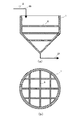
図2(a)、(b)は格子状の臨界抑止部材6を沈殿分離槽1の底部に上下複数に配置した例である。
(Modification)
2 to 4 show modified examples of the criticality restraining member.
FIGS. 2A and 2B are examples in which lattice-like critical deterring
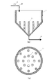
図3(a)、(b)は棒状の臨界抑止部材7を沈殿分離槽1の底部に複数配置した例である。なお、棒状の臨界抑止部材7は、その断面が円形、多角形等、種々の形状のものを用いることができる。
FIGS. 3A and 3B are examples in which a plurality of rod-like criticality restraining members 7 are arranged at the bottom of the
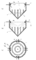
図4(a)、(b)は沈降分離槽1の底部に複数の円筒状の案内管10を設置し、その内部に中性子吸収材からなる棒状の臨界抑止部材8を挿入する例である。複数の棒状の臨界抑止部材8は、駆動機構11に取り付けられ、放射性廃液2の処理時に沈殿分離槽1の下部から駆動機構11(図示せず)によって案内管10の内部に挿入される。この臨界抑止部材8は可動式であるため、臨界抑止部材8の損傷検査、交換、形状変更等を適宜行うことができる。
また、案内管10を格子状、同心状に形成し、その形状に合わせて格子状又は同心状の臨界抑止部材を用いてもよい。
FIGS. 4A and 4B show an example in which a plurality of
Further, the
図2乃至図4のいずれの変形例でも、第1の実施形態と同様に、臨界抑止部材の個数、配置、高さ等は、沈殿分離槽1の容量、放射性廃液2の成分等に応じて適宜設計変更可能である。
In any of the modifications shown in FIGS. 2 to 4, the number, arrangement, height, etc. of the criticality restraining members depend on the capacity of the
(効果)
本発明の第1の実施形態によれば、沈降分離槽1を逆錘形状とし、沈降分離槽1の底部の傾斜角を放射性廃液2中のスラッジ3の安息角よりも大きな角度にすることによって、放射性廃液2中のスラッジ3を底部に向けて速やかに下降させスラッジ3を偏在させることなく略均一に堆積させることができる。沈降分離槽1の底部に堆積したスラッジ3は、沈降分離槽1の底部に配置した臨界抑制部材5〜8によって臨界に達するのを確実に防止することができる。これにより、大容量の放射性廃液2を安全、確実に処理できるため、放射性廃液の処理能力及び処理期間を大幅に向上させることができる。
(effect)
According to the first embodiment of the present invention, the sedimentation /
[第2の実施形態]
第2の実施形態に係る放射性廃液の沈降分離装置及び沈降分離方法について図5(a)〜(c)を参照して説明する。なお、第1の実施形態に係る装置の各部と同一部分には同一符号を付し、同一の構成については重複説明を省略する。
[Second Embodiment]
A radioactive waste liquid sedimentation separation apparatus and sedimentation separation method according to a second embodiment will be described with reference to FIGS. In addition, the same code | symbol is attached | subjected to the same part as each part of the apparatus which concerns on 1st Embodiment, and duplication description is abbreviate | omitted about the same structure.
(構成)
第2の実施形態は、沈降分離槽1の内壁面並びに臨界抑止部材5〜8及び案内管10の外周面にスラッジ3等の付着物が付着することを抑制するとともに、付着した付着物を除去するためのスラッジ洗浄部15を具備したことを特徴としている。
(Constitution)
In the second embodiment, deposits such as
スラッジ洗浄部15は、放射性廃液2の処理中に沈降分離槽1の上部に溜まった上澄液4を循環させる小型の循環ポンプ15aと、スラッジ3の排出後に沈降分離槽1の内壁面並びに臨界抑止部材5〜8及び案内管10の外周面をスプレー洗浄する噴射ノズル15bから構成され、図5(c)に示すように、沈降分離槽1の内周面に複数設置される。循環ポンプ15aには電源ケーブル17を介して外部から電源が供給され、噴射ノズル15bには外部に貯留された上澄液4又は水が配管18を通して供給される。
The
なお、循環ポンプ15a及び噴射ノズル15bの数及び配置は、沈降分離槽1の容量又は形状、臨界抑止部材5〜8の配置等に応じて、適宜変更可能である。例えば、循環ポンプ15a及び噴射ノズル15bを沈降分離槽1の内周面だけではなく、沈降分離槽1の内部空間に支持部材によって配置するようにしてもよい(図示せず)。また、スラッジ洗浄部15を循環ポンプ15a又は噴射ノズル15bのみから構成してもよい。
In addition, the number and arrangement | positioning of the
(作用)
このように構成された本第2の実施形態において、放射性廃液2の処理中に循環ポンプ15aを作動させ、沈降分離槽1の上部に貯溜した上澄液4を循環させる。これにより、沈降分離槽1内に上澄液4の循環流が生じ、沈降分離槽1の内周面並びに臨界抑止部材5〜8及び案内管10の外周にスラッジ3等が付着するのを抑制する。なお、循環ポンプ15aによって生起される水流は沈殿分離槽1の底部に堆積したスラッジ3を攪乱させたり舞い上げたりしない程度の水流に調節される。
(Function)
In the second embodiment configured as described above, the
次に、放射性廃液2の沈殿分離処理が終了し、スラッジ3が沈殿分離槽1から排出された後、ノズル15bから別途貯溜された上澄液4や水が沈殿分離槽1内に噴射され、沈降分離槽1の内周面並びに臨界抑止部材5〜8及び案内管10の外周面に付着した付着物を除去する。
Next, after the precipitation separation process of the radioactive
(効果)
本第2の実施形態によれば、沈降分離槽1の内周面に循環ポンプ15a及び噴射ノズル15bからなるスラッジ洗浄部15を設けたことにより、沈降分離槽1の内周面並びに臨界抑止部材5〜8及び案内管10の外周面へのスラッジ等の付着抑制及び付着物除去を効率的に行うことができるので、沈降分離装置の沈降分離能力を良好に保つことができる。
(effect)
According to the second embodiment, by providing the
[第3の実施形態]
第3の実施形態に係る放射性廃液の沈降分離装置及び沈降分離方法について図6乃至図9を参照して説明する。なお、第1及び第2の実施形態に係る装置の各部と同一部分には同一符号を付し、同一の構成については重複説明を省略する。
[Third Embodiment]
A radioactive waste liquid sedimentation separation apparatus and sedimentation separation method according to a third embodiment will be described with reference to FIGS. In addition, the same code | symbol is attached | subjected to the same part as each part of the apparatus which concerns on 1st and 2nd embodiment, and duplication description is abbreviate | omitted about the same structure.
(構成)
本第3の実施形態は臨界抑止部材として粒状の中性子吸収材(ホウケイ酸ガラス又はボロンカーバイド)を用いることを特徴とする。
(Constitution)
The third embodiment is characterized in that a granular neutron absorbing material (borosilicate glass or boron carbide) is used as a critical suppression member.
まず、図9を用いて本実施形態の原理について説明する。
図9は核燃料物質の代表的な元素であるウランとプルトニウムの金属酸化物と中性子吸収材として一般的に使用されるホウケイ酸ガラスとボロンカーバイドの30分後の水中での沈降距離(m;v×0.5h)に対する粒径dとの関係を示す図である。水中での沈降距離に対する粒径dは式(1)によって求められる。
First, the principle of this embodiment will be described with reference to FIG.
FIG. 9 shows the sedimentation distance in water (m; v) after 30 minutes of metal oxides of uranium and plutonium, which are typical elements of nuclear fuel materials, and borosilicate glass and boron carbide, which are generally used as neutron absorbers. It is a figure which shows the relationship with the particle size d with respect to x0.5h) . Particle size for sedimentation distance in water d is calculated by equation (1).

ここで、dは粒子の直径(m)、ηは水の20℃における粘性計数(Pa・s)、vは沈降速度(m/s)、ρSは粒子の密度(kg/m3)、ρwは水の密度(kg/m3)、gは重力加速度(m/s2)である。 Here, d is the particle diameter (m), η is the viscosity count of water at 20 ° C. (Pa · s), v is the sedimentation velocity (m / s), ρ S is the particle density (kg / m 3 ), ρ w is the density of water (kg / m 3 ), and g is the acceleration of gravity (m / s 2 ).
図9から放射性廃液2中に投入される粒状の臨界抑止部材9の粒径が核燃料物質(ウラン及びプルトニウムの金属酸化物:酸化ウラン及び酸化プルトニウム)の粒径の約3倍の場合に、沈降距離がほぼ同じになることがわかる。すなわち、図9において、沈降距離が約0.01m〜10mの範囲にわたって臨界抑止部材9(ホウケイ酸ガラス、ボロンカーバイド)の粒径は金属酸化物(酸化ウラン及び酸化プルトニウム)の粒径の約3倍となっていることが示されている。これは、核燃料物質の金属酸化物(酸化ウラン及び酸化プルトニウム)の密度が臨界抑止部材9の密度よりも大きいことによるものである。
From FIG. 9, when the particle size of the granular critical restraining
したがって、粒状の臨界抑止部材9(ホウケイ酸ガラス、ボロンカーバイド)の粒径を金属酸化物(酸化ウラン及び酸化プルトニウム)からなるスラッジの約3倍とすることで、堆積したスラッジ3中に粒状の臨界抑止部材9を略均一に混在させることが可能となる。
Therefore, the particle size of the granular critical restraining member 9 (borosilicate glass, boron carbide) is about three times that of the sludge made of metal oxide (uranium oxide and plutonium oxide). It becomes possible to mix the
図6は本第3の実施形態に係る沈降分離槽1の概略図で、粒状の臨界抑止部材9の投入部16を沈殿分離槽1の上部に設けている。
この投入部16には、放射性廃液2中に含まれる酸化ウラン及び酸化プルトニウムの最も頻度の高い粒径の約3倍の粒径の臨界抑止部材9が充填されており、放射性廃液2とともに沈降分離槽1内に順次投入される。
なお、放射性廃液2中に含まれる酸化ウラン及び酸化プルトニウムの粒径分布、粒径頻度はサンプリング等によって予め把握しておくことが望ましい。
FIG. 6 is a schematic view of the
The charging
In addition, it is desirable to grasp in advance the particle size distribution and particle size frequency of uranium oxide and plutonium oxide contained in the radioactive
(作用)
このように構成された本実施形態において、放射性廃液2が沈殿分離槽1内に充填されるときに粒状の臨界抑止部材9が投入部16から順次投入されるが、粒状の臨界抑止部材9の粒径を酸化ウラン及び/又は酸化プルトニウムの約3倍とすることで、臨界抑止部材9は放射性廃液2中の酸化ウラン及び酸化プルトニウムと略同速度の沈殿速度で沈殿分離槽1の底部にスラッジ3とともに堆積する。その際、粒状の臨界抑止部材9は、スラッジ3の上方又は下方に偏在することはなく、スラッジ3内に略均等に分散されて堆積する。これにより、沈殿分離処理中に臨界が発生するのを確実に防止することができる。
(Function)
In the present embodiment configured as described above, when the radioactive
また、沈殿処理後のスラッジ3は、図8に示すように、保管容器22に適宜排出されるが、その際も粒状の臨界抑止部材9が保管容器22内に略均等に混在しているため、保管容器22においても臨界が発生することはない。
Further, as shown in FIG. 8, the
(変形例)
上記実施形態では略臨界抑止部材9として一定の粒径を有する粒状の臨界抑止部材9が用いられるが、酸化ウラン及び酸化プルトニウムの粒径分布や粒径頻度に応じて2又は3以上の粒径の異なる臨界抑止部材を用いてもよい。例えば、放射性廃液2中の酸化ウラン及び酸化プルトニウムからなるスラッジの粒径が2つのピークを有するものであれば、図7に示すように、粒径の異なる2種類の臨界抑止部材9a、9bが用いられ、その粒径は対応する酸化ウラン及び酸化プルトニウムの粒径の略3倍に設定される。
(Modification)
In the above embodiment, the granular
ここで粒径の小さいスラッジを3a、粒径の大きいスラッジを3bとすれば、図7に示すように、粒径の大きいスラッジ3bはスラッジ3aの下方に堆積する。そして、スラッジ3aにはスラッジ3aの粒径の約3倍の小粒径の臨界抑止部材9aが略均一に混在し、スラッジ3bにはスラッジ3bの粒径の約3倍の大粒径の臨界抑止部材9bが略均一に混在することになる。
If the sludge having a small particle diameter is 3a and the sludge having a large particle diameter is 3b, the
(効果)
本第3の実施形態によれば、核燃料物質を含む放射性廃液2を沈降分離槽1に充填する際に、投入部16から所定の粒径を有する粒状の臨界抑止部材9を投入することで、沈殿分離槽1内の底部に堆積するスラッジ3中に臨界抑止部材9を略均等に混在させることができる。これにより、放射性廃液2の処理中に臨界が発生するのを確実に防止することができるため、放射性廃液2の沈降分離処理を安全に実施することができる。
(effect)
According to the third embodiment, when the radioactive
また、放射性廃液2中の酸化ウラン及び酸化プルトニウムの粒径が複数のピークを有するものであれば、それぞれの粒径の約3倍の粒径を有する複数種類の臨界抑止部材9a、9b・・・を用いることで、放射性廃液2の処理中に臨界が発生するのをさらに確実に防止することができる。
If the particle sizes of uranium oxide and plutonium oxide in the radioactive
さらに、沈殿分離後のスラッジ3を保管容器22に移管する場合でも、スラッジ3内には粒状の臨界抑止部材8が略均等に混在しているため、保管先でも臨界が発生するのを確実に防止することができる。
Further, even when the
以上、本発明のいくつかの実施形態を説明したが、これらの実施形態は、例として提示したものであり、発明の範囲を限定することは意図していない。例えば、沈降分離槽1の形状や大きさ、棒状等又は粒状の臨界抑止部材の大きさ、形状及び材質等は被処理液3の容積、成分や液媒の種類に応じて適宜変更され得るものである。また、棒状等及び粒状の臨界抑止部材を併用してもよい。
As mentioned above, although some embodiment of this invention was described, these embodiment is shown as an example and is not intending limiting the range of invention. For example, the shape and size of the
これら新規な実施形態は、その他の様々な形態で実施されることが可能であり、発明の要旨を逸脱しない範囲で、種々の省略、組み合わせ、置き換え、変更を行うことができる。これら実施形態やその変形は、発明の範囲や要旨に含まれるとともに、特許請求の範囲に記載された発明とその均等の範囲に含まれる。 These novel embodiments can be implemented in various other forms, and various omissions, combinations, replacements, and changes can be made without departing from the scope of the invention. These embodiments and modifications thereof are included in the scope and gist of the invention, and are included in the invention described in the claims and the equivalents thereof.
1…沈降分離槽、2…放射性廃液、3…スラッジ、4…上澄液、5〜8…臨界抑止部材、9…臨界抑止部材(粒状)、10…案内管、11…駆動機構、12…臨界モニタ、13…放射線量率計、13…スラッジ洗浄部、15a…循環ポンプ、15b…噴射ノズル、16…投入部、17…電源ケーブル、18…配管、20…供給配管、21…排出配管、22…保管容器。
DESCRIPTION OF
Claims (12)
前記粒状の臨界抑止部材の沈降速度は、前記放射性廃液中に含まれる核燃料物質の沈降速度と同等であることを特徴とする放射性廃液の沈殿分離装置。 A precipitation separation tank whose lower part is inclined in an inverted conical shape and into which radioactive waste liquid is injected; and a charging unit disposed in the upper part of the precipitation separation tank and charged with a plurality of granular critical suppression members into the precipitation separation tank; Have
The radioactive waste liquid sedimentation apparatus according to claim 1, wherein a sedimentation speed of the granular critical restraining member is equal to a sedimentation speed of a nuclear fuel material contained in the radioactive waste liquid.
Priority Applications (1)
| Application Number | Priority Date | Filing Date | Title |
|---|---|---|---|
| JP2013021479A JP6180748B2 (en) | 2013-02-06 | 2013-02-06 | Sedimentation separation apparatus and sedimentation separation method for radioactive liquid waste |
Applications Claiming Priority (1)
| Application Number | Priority Date | Filing Date | Title |
|---|---|---|---|
| JP2013021479A JP6180748B2 (en) | 2013-02-06 | 2013-02-06 | Sedimentation separation apparatus and sedimentation separation method for radioactive liquid waste |
Publications (2)
| Publication Number | Publication Date |
|---|---|
| JP2014153121A JP2014153121A (en) | 2014-08-25 |
| JP6180748B2 true JP6180748B2 (en) | 2017-08-16 |
Family
ID=51575134
Family Applications (1)
| Application Number | Title | Priority Date | Filing Date |
|---|---|---|---|
| JP2013021479A Active JP6180748B2 (en) | 2013-02-06 | 2013-02-06 | Sedimentation separation apparatus and sedimentation separation method for radioactive liquid waste |
Country Status (1)
| Country | Link |
|---|---|
| JP (1) | JP6180748B2 (en) |
Family Cites Families (11)
| Publication number | Priority date | Publication date | Assignee | Title |
|---|---|---|---|---|
| JPS5786094A (en) * | 1980-11-18 | 1982-05-28 | Tokyo Shibaura Electric Co | Operation method of purification process |
| JPS5950393A (en) * | 1982-08-26 | 1984-03-23 | ヌケム・ゲゼルシヤフト・ミツト・ベシユレンクテル・ハフツング | Container for storing safely nuclear fissile material solution in critical |
| JPS5940896U (en) * | 1982-09-08 | 1984-03-15 | 三井造船株式会社 | nuclear fuel solution storage tank |
| JPH0785116B2 (en) * | 1987-06-11 | 1995-09-13 | 日本原子力研究所 | Foaming device for criticality accident prevention |
| JP2637218B2 (en) * | 1989-01-30 | 1997-08-06 | 株式会社東芝 | Operation method of centrifugal clarifier |
| JPH0719033Y2 (en) * | 1989-04-14 | 1995-05-01 | 三菱マテリアル株式会社 | Drip tray |
| JPH0829596A (en) * | 1994-07-19 | 1996-02-02 | Toshiba Eng Co Ltd | Drip tray |
| JP3480878B2 (en) * | 1995-10-02 | 2003-12-22 | 株式会社東芝 | Radioactive waste liquid treatment equipment |
| JPH10132989A (en) * | 1996-10-31 | 1998-05-22 | Mitsubishi Heavy Ind Ltd | Solution tank |
| FR2927725B1 (en) * | 2008-02-18 | 2014-09-05 | Commissariat Energie Atomique | PROCESS FOR DECONTAMINATING A LIQUID EFFLUENT IN ONE OR MORE CHEMICAL ELEMENTS BY SOLID-LIQUID EXTRACTION UTILIZING A RECYCLING LOOP |
| FR2937634B1 (en) * | 2008-10-27 | 2011-09-30 | Commissariat Energie Atomique | METHOD FOR DECONTAMINATING A LIQUID EFFLUENT COMPRISING ONE OR MORE RADIOACTIVE CHEMICAL ELEMENTS BY FLUIDIZED BED TREATMENT |
-
2013
- 2013-02-06 JP JP2013021479A patent/JP6180748B2/en active Active
Also Published As
| Publication number | Publication date |
|---|---|
| JP2014153121A (en) | 2014-08-25 |
Similar Documents
| Publication | Publication Date | Title |
|---|---|---|
| US20130161260A1 (en) | Fluid Treatment System | |
| US10636532B2 (en) | Sodium cesium vapor trap system and method | |
| JP5779208B2 (en) | System and method for processing and storing coolant after an accident | |
| CN102859608B (en) | Isotope-specific separation and vitrification using ion-specific media | |
| US9406407B2 (en) | Radioactive capture system for severe accident containment of light water reactors (LWRS), and method thereof | |
| WO2016108727A1 (en) | Method for processing liquid radioactive waste and for the recovery thereof | |
| CN105070337A (en) | Spent fuel storage system with interpolating type neutron absorption device | |
| JP6180748B2 (en) | Sedimentation separation apparatus and sedimentation separation method for radioactive liquid waste | |
| KR101726974B1 (en) | A after applying the Passive cooling storage facility of light water reactor spent nuclear fuel container | |
| KR101556509B1 (en) | Pyro process equipment of spent nuclear fuel | |
| EP2788292B1 (en) | Fluid treatment system | |
| KR101740607B1 (en) | Processing method of reducing bulk of used nuclear fuel for heavy water reactor | |
| KR100962277B1 (en) | An apparatus for neutron counting with reducing the gamma-ray effects in spent fuel measurement | |
| KR101756267B1 (en) | A heat treatment furnace for producing mossbauer source | |
| KR101887782B1 (en) | Loading pattern of Cobalt Bundle | |
| JP6511358B2 (en) | Solidification treatment method of radioactive waste | |
| Bra¨ hler et al. | The PBMR Fuel Plant: Proven Technology in Advanced Safety Environment | |
| Aebi | Overview of Treatment and Conditioning Practices in Goesgen NPP | |
| Mazokin | Transport-Technological Scheme of High-Level SRW Management from the Reactor Facilities in the Northwest Russia | |
| Larrick et al. | Waste management implications of irradiated nuclear fuel storage | |
| Denton et al. | SOGIN Enriched Uranium Extraction (EUREX) Plant Spent Fuel Pool Cleaning and Decontamination Utilizing the SMART™ SAFE™ Solution-9317 | |
| Quinn et al. | Greater-than-Class C low-level radioactive waste characterization. Appendix H: Packaging factors for greater-than-Class C low-level radioactive waste | |
| Tuomisto | State of the Art for Severe Accident Source Term Estimation | |
| Barnabás et al. | Spent Fuel Storage Operational Experience With Increased Crud Activities | |
| Haigh et al. | Recent developments in power station waste management procedures |
Legal Events
| Date | Code | Title | Description |
|---|---|---|---|
| A621 | Written request for application examination |
Free format text: JAPANESE INTERMEDIATE CODE: A621 Effective date: 20150721 |
|
| A131 | Notification of reasons for refusal |
Free format text: JAPANESE INTERMEDIATE CODE: A131 Effective date: 20160426 |
|
| A977 | Report on retrieval |
Free format text: JAPANESE INTERMEDIATE CODE: A971007 Effective date: 20160427 |
|
| A521 | Written amendment |
Free format text: JAPANESE INTERMEDIATE CODE: A523 Effective date: 20160620 |
|
| A131 | Notification of reasons for refusal |
Free format text: JAPANESE INTERMEDIATE CODE: A131 Effective date: 20161115 |
|
| RD04 | Notification of resignation of power of attorney |
Free format text: JAPANESE INTERMEDIATE CODE: A7424 Effective date: 20170106 |
|
| A521 | Written amendment |
Free format text: JAPANESE INTERMEDIATE CODE: A523 Effective date: 20170111 |
|
| TRDD | Decision of grant or rejection written | ||
| A01 | Written decision to grant a patent or to grant a registration (utility model) |
Free format text: JAPANESE INTERMEDIATE CODE: A01 Effective date: 20170620 |
|
| A61 | First payment of annual fees (during grant procedure) |
Free format text: JAPANESE INTERMEDIATE CODE: A61 Effective date: 20170719 |
|
| R151 | Written notification of patent or utility model registration |
Ref document number: 6180748 Country of ref document: JP Free format text: JAPANESE INTERMEDIATE CODE: R151 |