JP6187323B2 - Image processing apparatus and image processing program - Google Patents
Image processing apparatus and image processing program Download PDFInfo
- Publication number
- JP6187323B2 JP6187323B2 JP2014042304A JP2014042304A JP6187323B2 JP 6187323 B2 JP6187323 B2 JP 6187323B2 JP 2014042304 A JP2014042304 A JP 2014042304A JP 2014042304 A JP2014042304 A JP 2014042304A JP 6187323 B2 JP6187323 B2 JP 6187323B2
- Authority
- JP
- Japan
- Prior art keywords
- image
- line segment
- module
- affine transformation
- transformation amount
- Prior art date
- Legal status (The legal status is an assumption and is not a legal conclusion. Google has not performed a legal analysis and makes no representation as to the accuracy of the status listed.)
- Expired - Fee Related
Links
Images






Classifications
-
- G—PHYSICS
- G06—COMPUTING OR CALCULATING; COUNTING
- G06T—IMAGE DATA PROCESSING OR GENERATION, IN GENERAL
- G06T3/00—Geometric image transformations in the plane of the image
- G06T3/02—Affine transformations
-
- G—PHYSICS
- G06—COMPUTING OR CALCULATING; COUNTING
- G06V—IMAGE OR VIDEO RECOGNITION OR UNDERSTANDING
- G06V10/00—Arrangements for image or video recognition or understanding
- G06V10/20—Image preprocessing
- G06V10/24—Aligning, centring, orientation detection or correction of the image
- G06V10/243—Aligning, centring, orientation detection or correction of the image by compensating for image skew or non-uniform image deformations
-
- G—PHYSICS
- G06—COMPUTING OR CALCULATING; COUNTING
- G06V—IMAGE OR VIDEO RECOGNITION OR UNDERSTANDING
- G06V30/00—Character recognition; Recognising digital ink; Document-oriented image-based pattern recognition
- G06V30/40—Document-oriented image-based pattern recognition
- G06V30/41—Analysis of document content
- G06V30/412—Layout analysis of documents structured with printed lines or input boxes, e.g. business forms or tables
Landscapes
- Engineering & Computer Science (AREA)
- Physics & Mathematics (AREA)
- General Physics & Mathematics (AREA)
- Theoretical Computer Science (AREA)
- Multimedia (AREA)
- Computer Vision & Pattern Recognition (AREA)
- Artificial Intelligence (AREA)
- Image Analysis (AREA)
- Editing Of Facsimile Originals (AREA)
- Character Input (AREA)
Description
本発明は、画像処理装置及び画像処理プログラムに関する。 The present invention relates to an image processing apparatus and an image processing program.
特許文献1には、フィールドの抽出に必要不可欠な十字点が存在しない帳票や、逆に膨大な数の十字点が存在する場合は、フィールドの抽出ができなかったり、フィールド抽出に誤差が生じて正確な文字認識を行えないことを課題とし、帳票の画像から文字認識の対象とする領域を特定する特徴点を抽出し、文字を記入した帳票の画像である文字記入画像と、この文字記入画像と同一の帳票の画像であって文字を記入していない文字未記入画像とから抽出した各特徴点を対応付けて、文字未記入画像に対する文字記入画像の位置関係を補正し、位置関係の補正の結果に基づいて文字記入画像上の文字認識の対象とする領域を抽出しこの文字認識の対象とする領域内の画像に対して文字認識処理を行うことが開示されている。
In
特許文献2には、入力帳票にずれがあっても精度の高い文字認識が可能な文字読取装置を実現することを課題とし、基準帳票のイメージを入力手段を介して取込み、線分抽出部を用いて該イメージから線分を抽出し、その座標を予め「線分フォーマット」として線分フォーマットメモリに格納しておき、線分抽出部は、入力帳票のイメージから線分を抽出し、その「線分情報」として比較部に与え、比較部により、「線分フォーマット」と「線分情報」とが比較され、入力帳票のずれに対応する誤差が求められ、切り出し部がイメージから切り出しして認識部で文字認識される文字記入位置の座標が、補正部によって誤差分だけ補正されることが開示されている。 In Patent Document 2, an object is to realize a character reader capable of highly accurate character recognition even if there is a deviation in the input form. The image of the reference form is taken in via the input means, and a line segment extraction unit is provided. The line segment is extracted from the image and stored in the line segment format memory as a “line segment format” in advance, and the line segment extraction unit extracts the line segment from the image of the input form. Line segment information "is given to the comparison unit. The comparison unit compares the" line segment format "with the" line segment information "to obtain an error corresponding to the deviation of the input form. It is disclosed that the coordinates of the character entry position recognized by the recognition unit are corrected by an error by the correction unit.
特許文献3には、帳票画像の位置ずれ、変倍の補正処理が不要で、帳票の物理レイアウトの違いに柔軟に対応できることを課題とし、帳票の項目名枠、記入枠の論理レイアウト情報を定義し、処理しようとする帳票の画像より抽出した枠領域の相対的位置関係を物理レイアウト情報と照らし合わせることによって、帳票画像の項目名枠及び記入枠に相当する枠領域を同定し、少なくとも記入枠と同定された枠領域の文字認識を行うことが開示されている。
本発明は、第2の画像に対する第1の画像の歪みを算出する場合において、本構成を有していない場合に比較して、処理時間を短くするようにした画像処理装置及び画像処理プログラムを提供することを目的としている。 The present invention provides an image processing apparatus and an image processing program in which the processing time is shortened when calculating the distortion of the first image with respect to the second image, compared to the case where the present configuration is not provided. It is intended to provide.
かかる目的を達成するための本発明の要旨とするところは、次の各項の発明に存する。
請求項1の発明は、第1の画像から線分を検出する検出手段と、前記線分のうち、長さ順で上位から予め定められた数の線分と、前記第1の画像の雛型となる第2の画像における線分との組を選択する選択手段と、前記線分の組を用いて、前記第2の画像に対する前記第1の画像の歪みを算出する算出手段を具備することを特徴とする画像処理装置である。
The gist of the present invention for achieving the object lies in the inventions of the following items.
The invention according to
請求項2の発明は、前記算出手段は、前記線分の組の2つからアフィン変換量を算出し、該アフィン変換量を用いた前記第1の画像と前記第2の画像の一致度に基づいて、前記歪みを示すアフィン変換量を選択することを特徴とする請求項1に記載の画像処理装置である。
According to a second aspect of the present invention, the calculation means calculates an affine transformation amount from two of the set of line segments, and determines the degree of coincidence between the first image and the second image using the affine transformation amount. The image processing apparatus according to
請求項3の発明は、前記一致度とは、前記第1の画像から検出される特徴点と前記第2の画像における特徴点について、前記アフィン変換量による変換後に、最近傍の関係にある組が、予め定められた距離内に収まっている個数であり、前記特徴点とは、前記線分の端点又は前記線分どうしがなす交点であることを特徴とする請求項2に記載の画像処理装置である。 According to a third aspect of the present invention, the degree of coincidence is a set in which a feature point detected from the first image and a feature point in the second image are in a closest relationship after conversion by the affine transformation amount. 3. The image processing according to claim 2, wherein the number is within a predetermined distance, and the feature point is an end point of the line segment or an intersection formed by the line segments. Device.
請求項4の発明は、前記第1の画像の特徴点と前記第2の画像の特徴点について、前記算出手段による算出処理後に、予め定められた距離内に収まっている最近傍の関係にある組から、最小2乗法によりアフィン変換量を算出する第2の算出手段をさらに具備することを特徴とする請求項1から3のいずれか一項に記載の画像処理装置である。
According to a fourth aspect of the present invention, the feature point of the first image and the feature point of the second image are in the nearest relationship within a predetermined distance after the calculation processing by the calculation unit. 4. The image processing apparatus according to
請求項5の発明は、前記第2の画像から線分を検出する第2の検出手段をさらに具備しており、前記第2の画像は、レイアウト情報を指示する枠が描かれており、該枠内は未記入の画像であることを特徴とする請求項1から4のいずれか一項に記載の画像処理装置である。
The invention of
請求項6の発明は、前記選択手段は、前記第2の画像の線分として、長さ順で上位から予め定められた数の線分を利用することを特徴とする請求項1から5のいずれか一項に記載の画像処理装置である。
The invention according to
請求項7の発明は、前記算出手段は、前記線分の組から算出されるアフィン変換量が異常値である場合、前記一致度の評価における特徴点の組の探索を行わないことを特徴とする請求項2から6のいずれか一項に記載の画像処理装置である。 The invention according to claim 7 is characterized in that, when the affine transformation amount calculated from the set of line segments is an abnormal value, the calculation means does not search for a set of feature points in the evaluation of coincidence. An image processing apparatus according to any one of claims 2 to 6.
請求項8の発明は、前記アフィン変換量によって、レイアウト情報の補正を行う補正手段をさらに具備することを特徴とする請求項1から7のいずれか一項に記載の画像処理装置である。
The invention according to claim 8 is the image processing apparatus according to any one of
請求項9の発明は、前記補正されたレイアウト情報に基づいて文字認識を行う文字認識手段をさらに具備することを特徴とする請求項8に記載の画像処理装置である。 The invention according to claim 9 is the image processing apparatus according to claim 8, further comprising character recognition means for performing character recognition based on the corrected layout information.
請求項10の発明は、コンピュータを、第1の画像から線分を検出する検出手段と、前記線分のうち、長さ順で上位から予め定められた数の線分と、前記第1の画像の雛型となる第2の画像における線分との組を選択する選択手段と、前記線分の組を用いて、前記第2の画像に対する前記第1の画像の歪みを算出する算出手段として機能させるための画像処理プログラムである。 According to a tenth aspect of the present invention, there is provided a computer for detecting a line segment from the first image, a predetermined number of line segments in the length order among the line segments, and the first segment. Selection means for selecting a pair with a line segment in the second image as a template of the image, and calculation means for calculating distortion of the first image with respect to the second image using the line segment set Is an image processing program for functioning as
請求項1の画像処理装置によれば、第2の画像に対する第1の画像の歪みを算出する場合において、本構成を有していない場合に比較して、処理時間を短くすることができる。 According to the image processing apparatus of the first aspect, when calculating the distortion of the first image with respect to the second image, the processing time can be shortened as compared with the case where the present configuration is not provided.
請求項2の画像処理装置によれば、第1の画像と第2の画像の一致度に基づいて、歪みを示すアフィン変換量を選択することができる。 According to the image processing apparatus of the second aspect, it is possible to select an affine transformation amount indicating distortion based on the degree of coincidence between the first image and the second image.
請求項3の画像処理装置によれば、一致度として、第1の画像から検出される特徴点と第2の画像における特徴点について、アフィン変換量による変換後に、最近傍の関係にある組が、予め定められた距離内に収まっている個数を用いることができる。
According to the image processing device of
請求項4の画像処理装置によれば、最小2乗法によりアフィン変換量を算出することができる。 According to the image processing apparatus of the fourth aspect, the affine transformation amount can be calculated by the least square method.
請求項5の画像処理装置によれば、第2の画像から線分を検出して用いることができる。 According to the image processing apparatus of the fifth aspect, a line segment can be detected from the second image and used.
請求項6の画像処理装置によれば、第2の画像の線分として、長さ順で上位から予め定められた数の線分を利用することができる。 According to the image processing apparatus of the sixth aspect, as the line segment of the second image, a predetermined number of line segments from the top in the order of length can be used.
請求項7の画像処理装置によれば、線分の組から算出されるアフィン変換量が異常値である場合、一致度の評価における特徴点の組の探索を行わないようにすることができる。 According to the image processing apparatus of the seventh aspect, when the affine transformation amount calculated from the pair of line segments is an abnormal value, it is possible not to search for a pair of feature points in the evaluation of coincidence.
請求項8の画像処理装置によれば、アフィン変換量によって、レイアウト情報の補正を行うことができる。 According to the image processing apparatus of the eighth aspect, the layout information can be corrected by the affine transformation amount.
請求項9の画像処理装置によれば、補正されたレイアウト情報に基づいて文字認識を行うことができる。 According to the image processing apparatus of the ninth aspect, character recognition can be performed based on the corrected layout information.
請求項10の画像処理プログラムによれば、第2の画像に対する第1の画像の歪みを算出する場合において、本構成を有していない場合に比較して、処理時間を短くすることができる。 According to the image processing program of the tenth aspect, when calculating the distortion of the first image with respect to the second image, the processing time can be shortened as compared with the case where the present configuration is not provided.
まず、本実施の形態を説明する前に、その前提又は本実施の形態を利用する画像処理装置について説明する。
文字等が記入された文書とその文書の雛型(以下、テンプレートともいう。文字が記入される前の状態の文書)とのマッチング処理に関する技術がある。例えば、文書として、主に帳票がある。特に、スキャンされた記入済みの帳票と、予め定められたレイアウト情報との位置ずれや回転、歪みの補正量を算出する技術に属する。
以下では、スキャン(撮影を含む概念である。以下、同様)された帳票の画像を受付画像と呼ぶ。
また、帳票の文字(レ点などのマークを含む概念である。以下、同様)認識の対象である領域の情報をレイアウト情報と呼ぶ。また、レイアウト情報を指示する枠線等が描かれた画像をテンプレート画像とする。テンプレート画像は、例えば、未記入の帳票の画像である。なお、レイアウト情報とテンプレート画像との歪み量はゼロ又は既知とする。また、受付画像に対応するテンプレート画像は既知とする。
受付画像は、テンプレート画像をプリントする場面や記入済みの情報をスキャンする場面において、レイアウト情報に対して位置ずれや回転、歪みが生じる。以下ではこれらを総称して歪み量と呼ぶ。本実施の形態における歪み量は、画像のアフィン変換量で表されるものとする。
画像のアフィン変換は数式1で表される。数式1において(x’,y’)Tは変換前の座標、(x,y)Tは変換後の座標を表す。画像のアフィン変換は平行移動・回転・拡大縮小を含み、6つのパラメータ(a,b,c,d,e,f)から成る。

There is a technique related to a matching process between a document in which characters or the like are entered and a template of the document (hereinafter also referred to as a template; a document in a state before characters are entered). For example, there are mainly forms as documents. In particular, the present invention belongs to a technique for calculating a correction amount for positional deviation, rotation, and distortion between a scanned completed form and predetermined layout information.
In the following, a scanned form image (which is a concept including photographing, hereinafter the same) is referred to as a received image.
In addition, information of a region that is a recognition target of a form character (a concept including marks such as check marks, etc .; hereinafter the same) is referred to as layout information. In addition, an image on which a frame line for instructing layout information is drawn is used as a template image. The template image is, for example, an image of a blank form. Note that the amount of distortion between the layout information and the template image is zero or known. Further, the template image corresponding to the reception image is assumed to be known.
The received image is misaligned, rotated, or distorted with respect to the layout information in a scene where a template image is printed or a case where scanned information is scanned. Hereinafter, these are collectively referred to as a distortion amount. It is assumed that the distortion amount in the present embodiment is represented by an affine transformation amount of an image.
The affine transformation of the image is expressed by
帳票の運用では、予め文字の記入領域やその情報の属性のレイアウトを設計し、これを枠線などで指示したテンプレート画像を作成する。続いてテンプレート画像をプリントした紙媒体等を記入者に提示し、記入者はレイアウトに従って情報を記入し、記入済みの画像をスキャンする。さらに、これを受付画像としてレイアウト情報に従って記入内容を認識し、情報を収集しようとする。テンプレート画像200の例を図2に示す。また、記入済みの受付画像300の例を図3に示す。
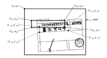
この過程において、特にプリント、スキャンの機械的な処理(紙送り等の処理)のために、図3の例に示すように受付画像とレイアウト情報の間に位置ずれや回転等の歪みが生じる。正しい情報を収集するためには歪み量を算出し、補正を行う必要がある。この様子を図4、図5の例に示す。図4に示す例は、図2の例に示したテンプレート画像200に対応付けられたレイアウト情報400である。分かりやすさのため1領域(対象領域410)のみの指定を図示しているが、複数領域あってもよい。原点を左上角の(x0,y0)として、対象領域410である四角形領域(xnw,ynw),(xne,yne),(xsw,ysw),(xse,yse)で囲まれた位置の情報を取得しようとしているが、歪みのために、図5の例に示す記入済みの受付画像とレイアウト情報の重ね合わせ画像500のように、受付画像300において前記の位置は(x’nw,y’nw),(x’ne,y’ne),(x’sw,y’sw),(x’se,y’se)となり、レイアウト情報と一致していない。そこで、歪みのアフィン変換量を推定し、数式1によってレイアウト情報又は受付画像を補正し、所望の位置の情報を取得しようとする。既存の技術では、枠線やその端点・交点など、テンプレート画像と受付画像で共通の特徴的な図形に基づいて上記の歪み量を算出する。例えば、対応する線分の組から平行移動量を算出する。また、対応する特徴点の組からアフィン変換量を算出する。特徴点は線分の交点や端点、矩形の角などである。
In the operation of a form, a character entry area and its attribute attribute layout are designed in advance, and a template image in which this is indicated by a frame line or the like is created. Subsequently, a paper medium or the like on which the template image is printed is presented to the writer, and the writer enters information according to the layout, and scans the completed image. Further, the user tries to collect information by recognizing the entry contents according to the layout information using the received image as an acceptance image. An example of the
In this process, particularly due to mechanical processing of printing and scanning (processing such as paper feeding), distortion such as displacement and rotation occurs between the received image and layout information as shown in the example of FIG. In order to collect correct information, it is necessary to calculate and correct the distortion amount. This is shown in the examples of FIGS. The example shown in FIG. 4 is
アフィン変換量を算出するには、テンプレート画像と受付画像の特徴点の組が(最低でも3組)必要である。しかし、一般に、テンプレート画像と受付画像の特徴点の組は未知である。アフィン変換の範囲においてその候補数は非常に多く、全ての組み合わせを検証する場合、莫大な処理時間を要する。
この問題に対して、レイアウト情報と受付画像の論理構造を利用する、特許文献3に示されるような既存の技術がある。しかし実環境においては、受付画像から検出される線分や特徴点には誤抽出や見逃しがあるため、これらの論理構造は必ずしも一致しない。線分の検出に誤検出がある例を図6に示す。この例では、受付画像600内に線分610のように、大きなレ点があるため、誤検出のレイアウトにおける線分として検出してしまう。
In order to calculate the affine transformation amount, a set of feature points of the template image and the reception image is required (at least three sets). However, in general, a set of feature points of the template image and the reception image is unknown. The number of candidates is very large in the range of affine transformation, and enormous processing time is required to verify all combinations.
In order to solve this problem, there is an existing technique as shown in
以下、図面に基づき本発明を実現するにあたっての好適な各種の実施の形態の例を説明する。
図1は、本実施の形態(以下に示す第1の実施の形態〜第6の実施の形態)を実現するための構成例についての概念的なモジュール構成図を示している。
なお、モジュールとは、一般的に論理的に分離可能なソフトウェア(コンピュータ・プログラム)、ハードウェア等の部品を指す。したがって、本実施の形態におけるモジュールはコンピュータ・プログラムにおけるモジュールのことだけでなく、ハードウェア構成におけるモジュールも指す。それゆえ、本実施の形態は、それらのモジュールとして機能させるためのコンピュータ・プログラム(コンピュータにそれぞれの手順を実行させるためのプログラム、コンピュータをそれぞれの手段として機能させるためのプログラム、コンピュータにそれぞれの機能を実現させるためのプログラム)、システム及び方法の説明をも兼ねている。ただし、説明の都合上、「記憶する」、「記憶させる」、これらと同等の文言を用いるが、これらの文言は、実施の形態がコンピュータ・プログラムの場合は、記憶装置に記憶させる、又は記憶装置に記憶させるように制御するの意である。また、モジュールは機能に一対一に対応していてもよいが、実装においては、1モジュールを1プログラムで構成してもよいし、複数モジュールを1プログラムで構成してもよく、逆に1モジュールを複数プログラムで構成してもよい。また、複数モジュールは1コンピュータによって実行されてもよいし、分散又は並列環境におけるコンピュータによって1モジュールが複数コンピュータで実行されてもよい。なお、1つのモジュールに他のモジュールが含まれていてもよい。また、以下、「接続」とは物理的な接続の他、論理的な接続(データの授受、指示、データ間の参照関係等)の場合にも用いる。「予め定められた」とは、対象としている処理の前に定まっていることをいい、本実施の形態による処理が始まる前はもちろんのこと、本実施の形態による処理が始まった後であっても、対象としている処理の前であれば、そのときの状況・状態に応じて、又はそれまでの状況・状態に応じて定まることの意を含めて用いる。「予め定められた値」が複数ある場合は、それぞれ異なった値であってもよいし、2以上の値(もちろんのことながら、全ての値も含む)が同じであってもよい。また、「Aである場合、Bをする」という意味を有する記載は、「Aであるか否かを判断し、Aであると判断した場合はBをする」の意味で用いる。ただし、Aであるか否かの判断が不要である場合を除く。
また、システム又は装置とは、複数のコンピュータ、ハードウェア、装置等がネットワーク(一対一対応の通信接続を含む)等の通信手段で接続されて構成されるほか、1つのコンピュータ、ハードウェア、装置等によって実現される場合も含まれる。「装置」と「システム」とは、互いに同義の用語として用いる。もちろんのことながら、「システム」には、人為的な取り決めである社会的な「仕組み」(社会システム)にすぎないものは含まない。
また、各モジュールによる処理毎に又はモジュール内で複数の処理を行う場合はその処理毎に、対象となる情報を記憶装置から読み込み、その処理を行った後に、処理結果を記憶装置に書き出すものである。したがって、処理前の記憶装置からの読み込み、処理後の記憶装置への書き出しについては、説明を省略する場合がある。なお、ここでの記憶装置としては、ハードディスク、RAM(Random Access Memory)、外部記憶媒体、通信回線を介した記憶装置、CPU(Central Processing Unit)内のレジスタ等を含んでいてもよい。
Hereinafter, examples of various preferred embodiments for realizing the present invention will be described with reference to the drawings.
FIG. 1 is a conceptual module configuration diagram of a configuration example for realizing the present embodiment (first to sixth embodiments described below).
The module generally refers to components such as software (computer program) and hardware that can be logically separated. Therefore, the module in the present embodiment indicates not only a module in a computer program but also a module in a hardware configuration. Therefore, the present embodiment is a computer program for causing these modules to function (a program for causing a computer to execute each procedure, a program for causing a computer to function as each means, and a function for each computer. This also serves as an explanation of the program and system and method for realizing the above. However, for the sake of explanation, the words “store”, “store”, and equivalents thereof are used. However, when the embodiment is a computer program, these words are stored in a storage device or stored in memory. It is the control to be stored in the device. Modules may correspond to functions one-to-one, but in mounting, one module may be configured by one program, or a plurality of modules may be configured by one program, and conversely, one module May be composed of a plurality of programs. The plurality of modules may be executed by one computer, or one module may be executed by a plurality of computers in a distributed or parallel environment. Note that one module may include other modules. Hereinafter, “connection” is used not only for physical connection but also for logical connection (data exchange, instruction, reference relationship between data, etc.). “Predetermined” means that the process is determined before the target process, and not only before the process according to this embodiment starts but also after the process according to this embodiment starts. In addition, if it is before the target processing, it is used in accordance with the situation / state at that time or with the intention to be decided according to the situation / state up to that point. When there are a plurality of “predetermined values”, they may be different values, or two or more values (of course, including all values) may be the same. In addition, the description having the meaning of “do B when it is A” is used in the meaning of “determine whether or not it is A and do B when it is judged as A”. However, the case where it is not necessary to determine whether or not A is excluded.
In addition, the system or device is configured by connecting a plurality of computers, hardware, devices, and the like by communication means such as a network (including one-to-one correspondence communication connection), etc., and one computer, hardware, device. The case where it implement | achieves by etc. is included. “Apparatus” and “system” are used as synonymous terms. Of course, the “system” does not include a social “mechanism” (social system) that is an artificial arrangement.
In addition, when performing a plurality of processes in each module or in each module, the target information is read from the storage device for each process, and the processing result is written to the storage device after performing the processing. is there. Therefore, description of reading from the storage device before processing and writing to the storage device after processing may be omitted. Here, the storage device may include a hard disk, a RAM (Random Access Memory), an external storage medium, a storage device via a communication line, a register in a CPU (Central Processing Unit), and the like.
本実施の形態である画像処理装置100は、第2の画像に対する第1の画像の歪みを算出するものであって、図1の例に示すように、画像読取装置110、テンプレート情報120、出力装置130と接続されている。
画像読取装置110は、画像処理装置100と接続されている。画像読取装置110は、テンプレートに文字等が記入された画像を読み取る機能を有している。例えば、スキャナ、カメラ等で画像を読み込むこと、ファックス等で通信回線を介して外部機器から画像を受信すること、ハードディスク(コンピュータに内蔵されているものの他に、ネットワークを介して接続されているもの等を含む)等に記憶されている画像を読み出すこと等が含まれる。画像は、2値画像、多値画像(カラー画像を含む)であってもよい。受け付ける画像は、1枚であってもよいし、複数枚であってもよい。また、画像の内容として、ビジネスに用いられる帳票等の文書等であって、テンプレートがあるものである。例えば、表、枠線、下線、トンボ等が含まれている文書であって、それら表等に関する情報がテンプレート情報になる。以下、表が含まれている文書を例示して説明する。
テンプレート情報120は、画像処理装置100と接続されている。テンプレート情報120は、テンプレートに関する情報(例えば、テンプレート線分727、テンプレート特徴点777、テンプレート画像905等)を画像処理装置100に渡す。
The
The
The
画像処理装置100は、後述する第1の実施の形態〜第6の実施の形態が含まれている。画像処理装置100の処理の概要を説明する。検出した枠線について、長さに基づいた候補の絞り込みを行うものである。例えば、現実的な処理時間で大きな歪み量に対応する。本実施の形態の処理フロー例を以下に示す。
−−−−− −−−−− −−−−−
step1.テンプレート画像の枠線を検出する。
step2.受付画像の枠線を検出する。
step3.受付画像の枠線を長い順にN個選択する。
step4.上記のように選択したN個の線分それぞれについて、テンプレート画像の枠線をM個選択し、テンプレート画像の線分と受付画像の線分の組を作成する。
step5.上記のように作成されたNM個のテンプレート画像とテンプレート画像の線分の組からさらに2つの組を選択し、アフィン変換量を算出する。
step6.上記のように作成されたN(N−1)M(M−1)個のアフィン変換量のうち、最適なものを選択する。
step7.上記のように選択されたアフィン変換量でテンプレート画像と受付画像の特徴点を対応付ける。
step8.上記のように対応付けられた対応点群からアフィン変換量を求め、これを歪み量とする。
−−−−− −−−−− −−−−−
なお、step4においてMとは、テンプレート画像から検出された線分の数である。また、step7において特徴点とは、線分の端点や交点である。また、step6において最適とは、テンプレート画像又は受付画像の特徴点を候補アフィン変換量で変換したとき、特徴点の配置の一致度が高いことを表す。
The
----- ------ ------
step1. Detect the border line of the template image.
step2. A frame line of the received image is detected.
step3. N frames of the received image are selected in the longest order.
step4. For each of the N line segments selected as described above, M frame lines of the template image are selected, and a pair of the template image line segment and the reception image line segment is created.
step5. Two more pairs are selected from the NM template images created as described above and the line segments of the template images, and the affine transformation amount is calculated.
step6. Of the N (N-1) M (M-1) affine transformation amounts created as described above, the optimum one is selected.
step7. The feature points of the template image and the received image are associated with the affine transformation amount selected as described above.
step8. The affine transformation amount is obtained from the corresponding point group associated as described above, and this is used as the distortion amount.
----- ------ ------
In
本実施の形態は、まず、テンプレート画像と受付画像から検出される線分の組により荒いアフィン変換量を算出する。荒いアフィン変換量は特徴点の組を作成できればよく、より正確なアフィン変換量は、全ての特徴点の組から算出する。
本実施の形態は、歪み量の範囲を仮定しない。その代わりに、テンプレート画像と受付画像の線分の組を限定することにより、処理時間の短縮を達成している。
一般に“線らしさ”とは長く細く湾曲が少ないほど高いと考えることができる。ゆえに、線らしさに基づいて線分を検出する技術は、一般に長細い線分ほど正確に検出する。受付画像から検出される線分は、誤抽出と見逃しの可能性があるが、長い線分であるほど正確に検出されていると期待できる。よって、歪み量を限定することなく高速化を達成するために、本実施の形態は、線分の長さに基づいて絞り込みを行う。
また、より遠い特徴点どうしからアフィン変換量を算出する方がよい。なぜならば、検出の微小な誤差の影響を線分の長さによって低減することができるためである。より長い線分の端点はより離れており、より正確なアフィン変換量が算出されると期待できる。
In this embodiment, first, a rough affine transformation amount is calculated based on a pair of line segments detected from the template image and the received image. The rough affine transformation amount only needs to create a set of feature points, and a more accurate affine transformation amount is calculated from all the feature point pairs.
In the present embodiment, the range of the distortion amount is not assumed. Instead, the processing time is shortened by limiting the combination of the line segment of the template image and the reception image.
In general, the “line-likeness” can be considered to be higher as it is longer and thinner and less curved. Therefore, a technique for detecting a line segment based on the likelihood of a line generally detects a thin line segment more accurately. Although the line segment detected from the received image may be erroneously extracted and missed, it can be expected that the longer the line segment, the more accurately it is detected. Therefore, in order to achieve high speed without limiting the amount of distortion, the present embodiment performs narrowing down based on the length of the line segment.
Also, it is better to calculate the affine transformation amount from farther feature points. This is because the influence of a minute detection error can be reduced by the length of the line segment. The end points of longer line segments are further away, and it can be expected that a more accurate affine transformation amount is calculated.
なお、step1、step2の線分の検出は、既存の技術を利用すればよい。
また、step5におけるアフィン変換量は、2つの線分の組から算出する。アフィン変換量を求めるには、最低3つの点の組が必要である。2つの線分の組には、最小で3つ、最大で5つの点の組があり、ここから任意の3組を選択すればよい。
また、step6における最適の評価は、以下に示すような例がある。まず、候補アフィン変換量でテンプレート画像の特徴点座標を変換する。続いて、受付画像の特徴点と変換後のテンプレート画像の特徴点について、互いに最近傍である特徴点の組を作成する。続いて、予め定められた値以上の距離を持つ組を棄却する。最後に組の総数を評価値とする。又は、組の距離の和の逆数を評価値とする。
Note that existing technology may be used to detect the line segments of step1 and step2.
Further, the affine transformation amount at
Moreover, there are examples as shown below for the optimum evaluation in
また、step8におけるアフィン変換量は、前述のように作成された特徴点の組から算出する。特徴点検出のノイズの影響を低減するために、例えば、最小2乗法を利用してアフィン変換量を求める。
なお、step3、step4において受付画像とテンプレート画像を入れ替えても同様の効用が得られる。また、step3において、短すぎる、傾きすぎる、距離が遠すぎるといった異常値を棄却してもよい。また、step4において、テンプレート画像の線分についてもまた長い順に絞り込みを行ってもよい。step5において、アフィン変換量が異常値となるような組み合わせは棄却して、step6以降の処理を軽減させてもよい。ここで、異常値とは、反転などの実環境では物理的に想定しえない拡縮や平行移動を示すアフィン変換量を指す。
また、前述の選択するN、Mは、文書毎(帳票毎)に設定可能としてもよい。また、Nは、Mに予め定められた1以上の計数を乗算した値としてもよい。Nは、Mと同数であることが理想的ではあるが、受付画像の線分数はテンプレート画像の線分数よりも多くなることが一般的であるからである。
Further, the affine transformation amount at step 8 is calculated from the set of feature points created as described above. In order to reduce the influence of noise in feature point detection, for example, an affine transformation amount is obtained using a least square method.
It should be noted that the same effect can be obtained by replacing the received image and the template image at
Further, the above-described N and M to be selected may be set for each document (for each form). N may be a value obtained by multiplying M by one or more predetermined counts. N is ideally the same as M, but the number of line segments in the received image is generally larger than the number of line segments in the template image.
出力装置130は、画像処理装置100と接続されている。出力装置130は、画像処理装置100による処理結果(アフィン変換量775、領域画像1295、文字認識結果1395)を出力する。例えば、ディスプレイ等の表示装置に表示すること、ハードディスク等の記憶装置に記憶すること、その処理結果を用いる他の情報処理装置へ渡すこと等が含まれる。
The
図7は、第1の実施の形態の構成例についての概念的なモジュール構成図である。図1の例に示した画像処理装置100の内容を示したものであり、線分検出モジュール710、線分選択モジュール720、線分ペア選択モジュール730、特徴点検出モジュール740、アフィン変換量算出Aモジュール750、特徴点ペア探索モジュール760、アフィン変換量算出Bモジュール770を有している。
処理の概要は、前述した画像処理装置100の処理と同様である。ただし、テンプレート画像から線分と特徴点を検出するのではなく、予めテンプレートの線分と特徴量の情報を抽出したものを使用している。
FIG. 7 is a conceptual module configuration diagram of a configuration example according to the first embodiment. The contents of the
The outline of the processing is the same as the processing of the
線分検出モジュール710は、線分選択モジュール720と接続されており、受付画像705を受け付け、線分選択モジュール720に受付画像線分715を渡す。つまり、線分検出モジュール710は、受付画像705から受付画像線分715を検出する。
線分選択モジュール720は、線分検出モジュール710、線分ペア選択モジュール730と接続されており、線分ペア選択モジュール730に受付画像線分725を渡す。線分選択モジュール720は、受付画像線分715のうち、長さ順で上位から予め定められた数の線分を選択し、その選択した線分を受付画像線分725として、線分ペア選択モジュール730に渡す。ここで、「長さ順」とは、長さの長い線分を上位とすることであり、いわゆる降順にソートすることに該当する。つまり、全ての検出された線分(受付画像線分720)からN個の線分(受付画像線分725)を選択する。
The line
The line
線分ペア選択モジュール730は、線分選択モジュール720、アフィン変換量算出Aモジュール750と接続されており、テンプレート線分727を受け付け、アフィン変換量算出Aモジュール750に線分ペア735を渡す。線分ペア選択モジュール730は、受付画像線分725とテンプレート線分727との組(ペア)を選択する。テンプレート線分727は、受付画像705の雛型となるテンプレート画像における線分である。つまり、線分ペア選択モジュール730は、受付画像線分725に対してテンプレート線分727を対応付けた線分の組(線分ペア735)を作成する。
特徴点検出モジュール740は、アフィン変換量算出Aモジュール750、特徴点ペア探索モジュール760と接続されており、受付画像705を受け付け、アフィン変換量算出Aモジュール750、特徴点ペア探索モジュール760に受付画像特徴点745を渡す。特徴点検出モジュール740は、既存の技術を用いて受付画像705内の特徴点を抽出し、その特徴点を受付画像特徴点745として出力する。ここで、特徴量とは、線分の端点又は線分どうしがなす交点である。
The line segment
The feature
アフィン変換量算出Aモジュール750は、線分ペア選択モジュール730、特徴点検出モジュール740、特徴点ペア探索モジュール760と接続されており、テンプレート特徴点777を受け付け、特徴点ペア探索モジュール760にアフィン変換量755を渡す。アフィン変換量算出Aモジュール750は線分ペア735を用いて、テンプレート画像に対する受付画像705の歪みを算出する。つまり、アフィン変換量算出Aモジュール750は、2つの線分の組(線分ペア735)からアフィン変換量755を算出し、最も受付画像特徴点745とテンプレート特徴点777の一致度が高いアフィン変換量755を出力する。ここで、線分のペアの2つからアフィン変換量を算出し、そのアフィン変換量を用いた受付画像705とテンプレート画像の一致度に基づいて、歪みを示すアフィン変換量を選択するようにしてもよい。ここで、一致度とは、受付画像705から検出される受付画像特徴点745とテンプレート画像におけるテンプレート特徴点777について、アフィン変換量による変換後に、最近傍の関係にある組が、予め定められた距離内に収まっている個数である。
The affine transformation amount
特徴点ペア探索モジュール760は、特徴点検出モジュール740、アフィン変換量算出Aモジュール750、アフィン変換量算出Bモジュール770と接続されており、テンプレート特徴点777を受け付け、アフィン変換量算出Bモジュール770に特徴点ペア765を渡す。特徴点ペア探索モジュール760は、アフィン変換量755に基づいて、特徴点の対応付けを行い特徴点の組(特徴点ペア765)を作成する。
アフィン変換量算出Bモジュール770は、特徴点ペア探索モジュール760と接続されており、アフィン変換量775を出力する。アフィン変換量算出Bモジュール770は、特徴点の組(特徴点ペア765)からアフィン変換量775を算出する。受付画像705の受付画像特徴点745とテンプレート画像のテンプレート特徴点777について、アフィン変換量算出Aモジュール750による算出処理後に、予め定められた距離内に収まっている最近傍の関係にある組から、最小2乗法によりアフィン変換量を算出する。
The feature point
The affine transformation amount
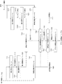
図8は、第1の実施の形態による処理例を示すフローチャートである。線分ペア選択モジュール730とアフィン変換量算出Aモジュール750における処理フローの例を示している。
受付画像の線分は、長さ順にソートされ、高々上位N個までしか参照されない。なお、n1,n2は、受付画像の線分のインデックスである。また、m1,m2はテンプレートの線分のインデックスである。また、アフィン変換量Aは、前述の数式1における6つのパラメータ(a,b,c,d,e,f)である。
歪み量であるアフィン変換量が分かることで、例えば、大量のスキャン投入の際に異常な姿勢の設置があれば、これを自動で検知・警告するようにしてもよい。
FIG. 8 is a flowchart illustrating a processing example according to the first exemplary embodiment. The example of the processing flow in the line segment
The line segments of the received image are sorted in order of length, and only up to the top N are referenced. Note that n 1 and n 2 are the line segment indexes of the received image. Also, m 1 and m 2 are template line segment indexes. Further, the affine transformation amount A is the six parameters (a, b, c, d, e, f) in the above-described
By knowing the amount of affine transformation, which is the amount of distortion, for example, if an abnormal posture is set when a large number of scans are input, this may be automatically detected and warned.
ステップS802では、受付画像の線分を長さ順にソートする。
ステップS804では、アフィン変換量Aに(0,0,0,0,0,0)を代入する。
ステップS806では、変数Sに0を代入する。
ステップS808では、変数n1に0を代入する。
ステップS810では、n1<Nであるか否かを判断し、n1<Nである場合はステップS812へ進み、それ以外の場合は処理を終了する(ステップS899)。
ステップS812では、変数n2にn1+1を代入する。
ステップS814では、n2<Nであるか否かを判断し、n2<Nである場合はステップS816へ進み、それ以外の場合はステップS844へ進む。
In step S802, the line segments of the received image are sorted in length order.
In step S804, (0, 0, 0, 0, 0, 0) is substituted into the affine transformation amount A.
In step S806, 0 is substituted into the variable S.
In step S808, 0 is substituted into a variable n 1.
In step S810, it is determined whether the n 1 <N, if it is n 1 <N proceeds to step S812, otherwise the process ends (step S899).
In step S812, n 1 +1 is assigned to the variable n 2 .
In step S814, it is determined whether the n 2 <N, if it is n 2 <N proceeds to step S 816, otherwise, the process goes to step S844.
ステップS816では、変数m1に0を代入する。
ステップS818では、m1<Mであるか否かを判断し、m1<Mである場合はステップS820へ進み、それ以外の場合はステップS842へ進む。
ステップS820では、変数m2に0を代入する。
ステップS822では、m2<Mであるか否かを判断し、m2<Mである場合はステップS824へ進み、それ以外の場合はステップS840へ進む。
ステップS824では、m2≠m1であるか否かを判断し、m2≠m1である場合はステップS826へ進み、それ以外の場合はステップS838へ進む。
ステップS826では、アフィン変換量算出を行う。(n1,m1)、(n2,m2)の線分ペアからアフィン変換量Aを算出する。
In
In step S818, it is determined whether the m 1 <M, if it is m 1 <M proceeds to step S820, otherwise, the process goes to step S842.
In step S820, 0 is substituted into the variable m 2.
In step S822, it is determined whether the m 2 <M, if it is m 2 <M proceeds to step S824, otherwise, the process goes to step S840.
In step S824, it is determined whether m 2 ≠ m 1 or not. If m 2 ≠ m 1 , the process proceeds to step S826; otherwise, the process proceeds to step S838.
In step S826, an affine transformation amount is calculated. The affine transformation amount A is calculated from the line segment pair of (n 1 , m 1 ) and (n 2 , m 2 ).
ステップS828では、特徴点対応付けを行う。アフィン変換量Aから特徴点の対応付けを行う。
ステップS830では、一致度算出を行う。対応する特徴点から一致度Sを算出する。
ステップS832では、Sselected<Sであるか否かを判断し、Sselected<Sである場合はステップS834へ進み、それ以外の場合はステップS838へ進む。
ステップS834では、AselectedにAを代入する。
ステップS836では、SselectedにSを代入する。
ステップS838では、m2にm2+1を代入する。
ステップS840では、m1にm1+1を代入する。
ステップS842では、n2にn2+1を代入する。
ステップS844では、n1にn1+1を代入する。
In step S828, feature point association is performed. The feature points are associated from the affine transformation amount A.
In step S830, the degree of coincidence is calculated. The degree of coincidence S is calculated from the corresponding feature point.
In step S832, it is determined whether the S selected <S, the process proceeds to step S834 if a S selected <S, and otherwise, the flow proceeds to step S838.
In step S834, A is substituted into A selected .
In step S836, S is substituted for S selected .
In step S838, substituting m 2 +1 to m 2.
In step S840, substituting m 1 +1 to m 1.
In step S842, substituting n 2 +1 to n 2.
In step S844, substituting n 1 +1 to n 1.
図9は、第2の実施の形態の構成例についての概念的なモジュール構成図である。第2の実施の形態における画像処理装置100は、線分検出モジュール710、線分選択モジュール720、線分ペア選択モジュール730、特徴点検出モジュール740、アフィン変換量算出Aモジュール750、特徴点ペア探索モジュール760、アフィン変換量算出Bモジュール770、線分検出モジュール910、特徴点検出モジュール920を有している。なお、第1の実施の形態と同種の部位には同一符号を付し重複した説明を省略する(以下、同様)。第2の実施の形態は、テンプレート画像を入力するものである。
テンプレート画像905も受付画像705と同様のスキャンやコピーのプロセスにより作成することで、受付画像705とテンプレート画像905で同様の劣化が生じる。これにより、線分の誤検出・見逃しを含んだより一致度の高い線分と特徴点の対応をとることとなる。
FIG. 9 is a conceptual module configuration diagram of a configuration example according to the second embodiment. The
The
線分ペア選択モジュール730は、線分選択モジュール720、アフィン変換量算出Aモジュール750、線分検出モジュール910と接続されており、アフィン変換量算出Aモジュール750に線分ペア735を渡す。
アフィン変換量算出Aモジュール750は、線分ペア選択モジュール730、特徴点検出モジュール740、特徴点ペア探索モジュール760、特徴点検出モジュール920と接続されており、特徴点ペア探索モジュール760にアフィン変換量755を渡す。
特徴点ペア探索モジュール760は、特徴点検出モジュール740、アフィン変換量算出Aモジュール750、アフィン変換量算出Bモジュール770、特徴点検出モジュール920と接続されており、アフィン変換量算出Bモジュール770に特徴点ペア765を渡す。
線分検出モジュール910は、線分ペア選択モジュール730と接続されており、テンプレート画像905を受け付け、線分ペア選択モジュール730にテンプレート線分727を渡す。線分検出モジュール910は、テンプレート画像905からテンプレート線分727を検出する。ここで、テンプレート画像905は、レイアウト情報を指示する枠が描かれており、その枠内は未記入の画像である。つまり、受付画像705の記入前の画像である。線分検出モジュール710と同等の処理を行う。
特徴点検出モジュール920は、アフィン変換量算出Aモジュール750、特徴点ペア探索モジュール760と接続されており、テンプレート画像905を受け付け、アフィン変換量算出Aモジュール750、特徴点ペア探索モジュール760にテンプレート特徴点777を渡す。特徴点検出モジュール740と同等の処理を行う。
The line segment
The affine transformation amount
The feature point
The line
The feature
図10は、第3の実施の形態の構成例についての概念的なモジュール構成図である。第3の実施の形態における画像処理装置100は、線分検出モジュール710、線分選択モジュール720、線分ペア選択モジュール730、特徴点検出モジュール740、アフィン変換量算出Aモジュール750、特徴点ペア探索モジュール760、アフィン変換量算出Bモジュール770、線分検出モジュール910、特徴点検出モジュール920、線分選択モジュール1020を有している。テンプレート線分の選択を行う例である。
線分ペア選択モジュール730は、線分選択モジュール720、アフィン変換量算出Aモジュール750、線分選択モジュール1020と接続されており、アフィン変換量算出Aモジュール750に線分ペア735を渡す。
線分検出モジュール910は、線分選択モジュール1020と接続されており、テンプレート画像905を受け付け、線分選択モジュール1020にテンプレート線分1015を渡す。
線分選択モジュール1020は、線分検出モジュール910、線分ペア選択モジュール730と接続されており、線分ペア選択モジュール730にテンプレート線分727を渡す。線分選択モジュール1020は、テンプレート画像905のテンプレート線分1015として、長さ順で上位から予め定められた数の線分を利用する。つまり、テンプレート線分1015から長さの長いものを選択して、その選択した線分をテンプレート線分727として出力する。テンプレート線分1015に対しても長さに基づいた取捨選択を行うものであり、線分選択モジュール720と同等の処理を行う。
FIG. 10 is a conceptual module configuration diagram of a configuration example according to the third embodiment. The
The line segment
The line
The line
図11は、第4の実施の形態の構成例についての概念的なモジュール構成図である。第4の実施の形態における画像処理装置100は、線分検出モジュール710、線分選択モジュール720、線分ペア選択モジュール730、特徴点検出モジュール740、アフィン変換量算出Aモジュール750、特徴点ペア探索モジュール760、アフィン変換量算出Bモジュール770、線分検出モジュール910、特徴点検出モジュール920、線分選択モジュール1020、アフィン変換量算出Cモジュール1150を有している。異常な線分の組み合わせを棄却する例である。
線分ペア選択モジュール730は、線分選択モジュール720、線分選択モジュール1020、アフィン変換量算出Cモジュール1150と接続されており、アフィン変換量算出Cモジュール1150に線分ペア735を渡す。
アフィン変換量算出Cモジュール1150は、線分ペア選択モジュール730、特徴点検出モジュール740、特徴点ペア探索モジュール760、特徴点検出モジュール920と接続されており、変換範囲1135を受け付け、特徴点ペア探索モジュール760にアフィン変換量755を渡す。アフィン変換量算出Cモジュール1150は、線分ペア735から算出されるアフィン変換量が異常値である場合、一致度の評価における特徴点のペアの探索を行わない。つまり、アフィン変換量算出Cモジュール1150は、特徴点による一致度を評価する前に、変換範囲1135に収まらないアフィン変換量を異常値と判定し棄却する。図8に示したフローチャート例における、特徴点対応付け処理(ステップS828)の直前で棄却を行えばよい。
特徴点ペア探索モジュール760は、特徴点検出モジュール740、アフィン変換量算出Cモジュール1150、アフィン変換量算出Bモジュール770、特徴点検出モジュール920と接続されており、アフィン変換量算出Bモジュール770に特徴点ペア765を渡す。
FIG. 11 is a conceptual module configuration diagram of a configuration example according to the fourth embodiment. The
The line segment
The affine transformation amount
The feature point
図12は、第5の実施の形態の構成例についての概念的なモジュール構成図である。第5の実施の形態における画像処理装置100は、線分検出モジュール710、線分選択モジュール720、線分ペア選択モジュール730、特徴点検出モジュール740、アフィン変換量算出Aモジュール750、特徴点ペア探索モジュール760、アフィン変換量算出Bモジュール770、アフィン変換モジュール1280、領域切り出しモジュール1290を有している。レイアウト情報の補正を行う例である。
アフィン変換量算出Bモジュール770は、特徴点ペア探索モジュール760、アフィン変換モジュール1280と接続されており、アフィン変換モジュール1280にアフィン変換量775を渡す。
アフィン変換モジュール1280は、アフィン変換量算出Bモジュール770、領域切り出しモジュール1290と接続されており、レイアウト情報1277を受け付け、領域切り出しモジュール1290にレイアウト情報1285を渡す。アフィン変換モジュール1280は、アフィン変換量算出Bモジュール770が算出したアフィン変換量775によって、レイアウト情報1277の位置情報を補正する。補正は数式1の通りである。実環境で発生した歪みを補正したレイアウト情報1285が得られる。
領域切り出しモジュール1290は、アフィン変換モジュール1280と接続されており、レイアウト情報1285を受け取って、領域画像1295を出力する。つまり、補正されたレイアウト情報1285に基づいて、領域を切り出すことで、所望の位置の領域画像1295(記入情報)が得られる。受付画像705ではなく、レイアウト情報1285を補正することで、画像編集による誤差がなく、また、補正すべき点数が少なくなる。
FIG. 12 is a conceptual module configuration diagram of a configuration example according to the fifth embodiment. The
The affine transformation amount
The
The
図13は、第6の実施の形態の構成例についての概念的なモジュール構成図である。第6の実施の形態における画像処理装置100は、線分検出モジュール710、線分選択モジュール720、線分ペア選択モジュール730、特徴点検出モジュール740、アフィン変換量算出Aモジュール750、特徴点ペア探索モジュール760、アフィン変換量算出Bモジュール770、アフィン変換モジュール1280、領域切り出しモジュール1290、文字認識モジュール1390を有している。文字認識を行う例である。
領域切り出しモジュール1290は、アフィン変換モジュール1280、文字認識モジュール1390と接続されており、文字認識モジュール1390に領域画像1295を渡す。
文字認識モジュール1390は、領域切り出しモジュール1290と接続されており、文字認識結果1395を出力する。文字認識モジュール1390は、補正されたレイアウト情報1285に基づいて文字認識を行う。つまり、文字認識モジュール1390は、領域画像1295に対して文字認識を行い、文字認識結果1395を出力する。文字認識は、既存の技術を利用すればよい。
なお、図12、図13に示した例は、第1の実施の形態にモジュール(アフィン変換モジュール1280、領域切り出しモジュール1290、文字認識モジュール1390)を付加しているが、第2の実施の形態等に対して、同様にモジュールを付加してもよい。
FIG. 13 is a conceptual module configuration diagram of a configuration example according to the sixth embodiment. The
The
The
In the example shown in FIGS. 12 and 13, modules (
図14を参照して、本実施の形態の画像処理装置のハードウェア構成例について説明する。図14に示す構成は、例えばパーソナルコンピュータ(PC)などによって構成されるものであり、スキャナ等のデータ読み取り部1417と、プリンタなどのデータ出力部1418を備えたハードウェア構成例を示している。
A hardware configuration example of the image processing apparatus according to the present embodiment will be described with reference to FIG. The configuration illustrated in FIG. 14 is configured by, for example, a personal computer (PC), and illustrates a hardware configuration example including a data reading unit 1417 such as a scanner and a
CPU(Central Processing Unit)1401は、前述の実施の形態において説明した各種のモジュール、すなわち、線分検出モジュール710、線分選択モジュール720、線分ペア選択モジュール730、特徴点検出モジュール740、アフィン変換量算出Aモジュール750、特徴点ペア探索モジュール760、アフィン変換量算出Bモジュール770、線分検出モジュール910、特徴点検出モジュール920、線分選択モジュール1020、アフィン変換量算出Cモジュール1150、アフィン変換モジュール1280、領域切り出しモジュール1290、文字認識モジュール1390等の各モジュールの実行シーケンスを記述したコンピュータ・プログラムにしたがった処理を実行する制御部である。
A CPU (Central Processing Unit) 1401 includes various modules described in the above embodiments, that is, a line
ROM(Read Only Memory)1402は、CPU1401が使用するプログラムや演算パラメータ等を格納する。RAM(Random Access Memory)1403は、CPU1401の実行において使用するプログラムや、その実行において適宜変化するパラメータ等を格納する。これらはCPUバスなどから構成されるホストバス1404により相互に接続されている。 A ROM (Read Only Memory) 1402 stores programs used by the CPU 1401, calculation parameters, and the like. A RAM (Random Access Memory) 1403 stores programs used in the execution of the CPU 1401, parameters that change as appropriate during the execution, and the like. These are connected to each other by a host bus 1404 including a CPU bus.
ホストバス1404は、ブリッジ1405を介して、PCI(Peripheral Component Interconnect/Interface)バスなどの外部バス1406に接続されている。
The host bus 1404 is connected to an
キーボード1408、マウス等のポインティングデバイス1409は、操作者により操作される入力デバイスである。ディスプレイ1410は、液晶表示装置又はCRT(Cathode Ray Tube)などがあり、各種情報をテキストやイメージ情報として表示する。
A
HDD(Hard Disk Drive)1411は、ハードディスクを内蔵し、ハードディスクを駆動し、CPU1401によって実行するプログラムや情報を記録又は再生させる。ハードディスクには、受付画像705、テンプレート線分727、テンプレート特徴点777、アフィン変換量775、領域画像1295、文字認識結果1395などが格納される。さらに、その他の各種のデータ処理プログラム等、各種コンピュータ・プログラムが格納される。
An HDD (Hard Disk Drive) 1411 includes a hard disk, drives the hard disk, and records or reproduces a program executed by the CPU 1401 and information. The hard disk stores a received
ドライブ1412は、装着されている磁気ディスク、光ディスク、光磁気ディスク、又は半導体メモリ等のリムーバブル記録媒体1413に記録されているデータ又はプログラムを読み出して、そのデータ又はプログラムを、インタフェース1407、外部バス1406、ブリッジ1405、及びホストバス1404を介して接続されているRAM1403に供給する。リムーバブル記録媒体1413も、ハードディスクと同様のデータ記録領域として利用可能である。
The
接続ポート1414は、外部接続機器1415を接続するポートであり、USB、IEEE1394等の接続部を持つ。接続ポート1414は、インタフェース1407、及び外部バス1406、ブリッジ1405、ホストバス1404等を介してCPU1401等に接続されている。通信部1416は、通信回線に接続され、外部とのデータ通信処理を実行する。データ読み取り部1417は、例えばスキャナであり、ドキュメントの読み取り処理を実行する。データ出力部1418は、例えばプリンタであり、ドキュメントデータの出力処理を実行する。
The
なお、図14に示す画像処理装置のハードウェア構成は、1つの構成例を示すものであり、本実施の形態は、図14に示す構成に限らず、本実施の形態において説明したモジュールを実行可能な構成であればよい。例えば、一部のモジュールを専用のハードウェア(例えば特定用途向け集積回路(Application Specific Integrated Circuit:ASIC)等)で構成してもよく、一部のモジュールは外部のシステム内にあり通信回線で接続しているような形態でもよく、さらに図14に示すシステムが複数互いに通信回線によって接続されていて互いに協調動作するようにしてもよい。また、複写機、ファックス、スキャナ、プリンタ、複合機(スキャナ、プリンタ、複写機、ファックス等のいずれか2つ以上の機能を有している画像処理装置)などに組み込まれていてもよい。 Note that the hardware configuration of the image processing apparatus illustrated in FIG. 14 illustrates one configuration example, and the present embodiment is not limited to the configuration illustrated in FIG. 14, and the modules described in the present embodiment are executed. Any configuration is possible. For example, some modules may be configured with dedicated hardware (for example, Application Specific Integrated Circuit (ASIC), etc.), and some modules are in an external system and connected via a communication line In addition, a plurality of systems shown in FIG. 14 may be connected to each other via communication lines so as to cooperate with each other. Further, it may be incorporated in a copying machine, a fax machine, a scanner, a printer, a multifunction machine (an image processing apparatus having any two or more functions of a scanner, a printer, a copying machine, a fax machine, etc.).
なお、説明したプログラムについては、記録媒体に格納して提供してもよく、また、そのプログラムを通信手段によって提供してもよい。その場合、例えば、前記説明したプログラムについて、「プログラムを記録したコンピュータ読み取り可能な記録媒体」の発明として捉えてもよい。
「プログラムを記録したコンピュータ読み取り可能な記録媒体」とは、プログラムのインストール、実行、プログラムの流通などのために用いられる、プログラムが記録されたコンピュータで読み取り可能な記録媒体をいう。
なお、記録媒体としては、例えば、デジタル・バーサタイル・ディスク(DVD)であって、DVDフォーラムで策定された規格である「DVD−R、DVD−RW、DVD−RAM等」、DVD+RWで策定された規格である「DVD+R、DVD+RW等」、コンパクトディスク(CD)であって、読出し専用メモリ(CD−ROM)、CDレコーダブル(CD−R)、CDリライタブル(CD−RW)等、ブルーレイ・ディスク(Blu−ray(登録商標) Disc)、光磁気ディスク(MO)、フレキシブルディスク(FD)、磁気テープ、ハードディスク、読出し専用メモリ(ROM)、電気的消去及び書換可能な読出し専用メモリ(EEPROM(登録商標))、フラッシュ・メモリ、ランダム・アクセス・メモリ(RAM)、SD(Secure Digital)メモリーカード等が含まれる。
そして、前記のプログラム又はその一部は、前記記録媒体に記録して保存や流通等させてもよい。また、通信によって、例えば、ローカル・エリア・ネットワーク(LAN)、メトロポリタン・エリア・ネットワーク(MAN)、ワイド・エリア・ネットワーク(WAN)、インターネット、イントラネット、エクストラネット等に用いられる有線ネットワーク、あるいは無線通信ネットワーク、さらにこれらの組み合わせ等の伝送媒体を用いて伝送させてもよく、また、搬送波に乗せて搬送させてもよい。
さらに、前記のプログラムは、他のプログラムの一部分であってもよく、あるいは別個のプログラムと共に記録媒体に記録されていてもよい。また、複数の記録媒体に分割して
記録されていてもよい。また、圧縮や暗号化など、復元可能であればどのような態様で記録されていてもよい。
The program described above may be provided by being stored in a recording medium, or the program may be provided by communication means. In that case, for example, the above-described program may be regarded as an invention of a “computer-readable recording medium recording the program”.
The “computer-readable recording medium on which a program is recorded” refers to a computer-readable recording medium on which a program is recorded, which is used for program installation, execution, program distribution, and the like.
The recording medium is, for example, a digital versatile disc (DVD), which is a standard established by the DVD Forum, such as “DVD-R, DVD-RW, DVD-RAM,” and DVD + RW. Standard “DVD + R, DVD + RW, etc.”, compact disc (CD), read-only memory (CD-ROM), CD recordable (CD-R), CD rewritable (CD-RW), Blu-ray disc ( Blu-ray (registered trademark) Disc), magneto-optical disk (MO), flexible disk (FD), magnetic tape, hard disk, read-only memory (ROM), electrically erasable and rewritable read-only memory (EEPROM (registered trademark)) )), Flash memory, Random access memory (RAM) SD (Secure Digital) memory card and the like.
The program or a part of the program may be recorded on the recording medium for storage or distribution. Also, by communication, for example, a local area network (LAN), a metropolitan area network (MAN), a wide area network (WAN), a wired network used for the Internet, an intranet, an extranet, etc., or wireless communication It may be transmitted using a transmission medium such as a network or a combination of these, or may be carried on a carrier wave.
Furthermore, the program may be a part of another program, or may be recorded on a recording medium together with a separate program. Moreover, it may be divided and recorded on a plurality of recording media. Further, it may be recorded in any manner as long as it can be restored, such as compression or encryption.
100…画像処理装置
110…画像読取装置
120…テンプレート情報
130…出力装置
705…受付画像
710…線分検出モジュール
715…受付画像線分
720…線分選択モジュール
725…受付画像線分
727…テンプレート線分
730…線分ペア選択モジュール
735…線分ペア
740…特徴点検出モジュール
745…受付画像特徴点
750…アフィン変換量算出Aモジュール
755…アフィン変換量
760…特徴点ペア探索モジュール
765…特徴点ペア
770…アフィン変換量算出Bモジュール
775…アフィン変換量
777…テンプレート特徴点
905…テンプレート画像
910…線分検出モジュール
920…特徴点検出モジュール
1015…テンプレート線分
1020…線分選択モジュール
1135…変換範囲
1150…アフィン変換量算出Cモジュール
1277…レイアウト情報
1280…アフィン変換モジュール
1285…レイアウト情報
1290…領域切り出しモジュール
1295…領域画像
1390…文字認識モジュール
1395…文字認識結果
DESCRIPTION OF
Claims (10)
前記線分のうち、長さ順で上位から予め定められた数の線分と、前記第1の画像の雛型となる第2の画像における線分との組を選択する選択手段と、
前記線分の組を用いて、前記第2の画像に対する前記第1の画像の歪みを算出する算出手段
を具備することを特徴とする画像処理装置。 Detecting means for detecting a line segment from the first image;
A selection means for selecting a set of a predetermined number of line segments from the top in the order of the length of the line segments and a line segment in the second image as a template of the first image;
An image processing apparatus comprising: calculation means for calculating distortion of the first image with respect to the second image using the set of line segments.
ことを特徴とする請求項1に記載の画像処理装置。 The calculation means calculates an affine transformation amount from two of the set of line segments, and indicates the distortion based on a degree of coincidence between the first image and the second image using the affine transformation amount. The image processing apparatus according to claim 1, wherein an affine transformation amount is selected.
前記特徴点とは、前記線分の端点又は前記線分どうしがなす交点である
ことを特徴とする請求項2に記載の画像処理装置。 The degree of coincidence refers to a predetermined distance between a feature point detected from the first image and a feature point in the second image, which is in a closest relationship after conversion by the affine transformation amount. It is the number that is contained within,
The image processing apparatus according to claim 2, wherein the feature point is an end point of the line segment or an intersection formed by the line segments.
をさらに具備することを特徴とする請求項1から3のいずれか一項に記載の画像処理装置。 About the feature point of the first image and the feature point of the second image, from the set in the nearest relationship within the predetermined distance after the calculation processing by the calculation means, the least square method is used. The image processing apparatus according to claim 1, further comprising: a second calculation unit that calculates an affine transformation amount.
をさらに具備しており、
前記第2の画像は、レイアウト情報を指示する枠が描かれており、該枠内は未記入の画像である
ことを特徴とする請求項1から4のいずれか一項に記載の画像処理装置。 A second detection means for detecting a line segment from the second image;
The image processing apparatus according to claim 1, wherein the second image has a frame indicating layout information drawn therein, and the frame is an unfilled image. .
ことを特徴とする請求項1から5のいずれか一項に記載の画像処理装置。 The selection means uses a predetermined number of line segments from the top in the order of length as the line segments of the second image. 6. Image processing device.
ことを特徴とする請求項2から6のいずれか一項に記載の画像処理装置。 The calculation means does not search for a set of feature points in the evaluation of the coincidence when the affine transformation amount calculated from the set of line segments is an abnormal value. The image processing apparatus according to any one of claims.
をさらに具備することを特徴とする請求項1から7のいずれか一項に記載の画像処理装置。 The image processing apparatus according to claim 1, further comprising a correction unit that corrects layout information based on the affine transformation amount.
をさらに具備することを特徴とする請求項8に記載の画像処理装置。 The image processing apparatus according to claim 8, further comprising: a character recognition unit that performs character recognition based on the corrected layout information.
第1の画像から線分を検出する検出手段と、
前記線分のうち、長さ順で上位から予め定められた数の線分と、前記第1の画像の雛型となる第2の画像における線分との組を選択する選択手段と、
前記線分の組を用いて、前記第2の画像に対する前記第1の画像の歪みを算出する算出手段
として機能させるための画像処理プログラム。 Computer
Detecting means for detecting a line segment from the first image;
A selection means for selecting a set of a predetermined number of line segments from the top in the order of the length of the line segments and a line segment in the second image as a template of the first image;
An image processing program for functioning as calculation means for calculating distortion of the first image with respect to the second image using the set of line segments.
Priority Applications (2)
| Application Number | Priority Date | Filing Date | Title |
|---|---|---|---|
| JP2014042304A JP6187323B2 (en) | 2014-03-05 | 2014-03-05 | Image processing apparatus and image processing program |
| US14/482,577 US9626738B2 (en) | 2014-03-05 | 2014-09-10 | Image processing apparatus, image processing method, and storage medium |
Applications Claiming Priority (1)
| Application Number | Priority Date | Filing Date | Title |
|---|---|---|---|
| JP2014042304A JP6187323B2 (en) | 2014-03-05 | 2014-03-05 | Image processing apparatus and image processing program |
Publications (2)
| Publication Number | Publication Date |
|---|---|
| JP2015169978A JP2015169978A (en) | 2015-09-28 |
| JP6187323B2 true JP6187323B2 (en) | 2017-08-30 |
Family
ID=54017867
Family Applications (1)
| Application Number | Title | Priority Date | Filing Date |
|---|---|---|---|
| JP2014042304A Expired - Fee Related JP6187323B2 (en) | 2014-03-05 | 2014-03-05 | Image processing apparatus and image processing program |
Country Status (2)
| Country | Link |
|---|---|
| US (1) | US9626738B2 (en) |
| JP (1) | JP6187323B2 (en) |
Families Citing this family (10)
| Publication number | Priority date | Publication date | Assignee | Title |
|---|---|---|---|---|
| JP6690089B2 (en) | 2016-04-25 | 2020-04-28 | 富士通株式会社 | Form recognition method, form recognition device, and form recognition program |
| JP6574920B1 (en) | 2018-07-06 | 2019-09-11 | 楽天株式会社 | Image processing system, image processing method, and program |
| JP6574921B1 (en) * | 2018-07-06 | 2019-09-11 | 楽天株式会社 | Image processing system, image processing method, and program |
| JP2020095624A (en) * | 2018-12-14 | 2020-06-18 | 株式会社デンソーテン | Image processing device and image processing method |
| CN111989692B (en) * | 2019-09-30 | 2024-08-16 | 北京市商汤科技开发有限公司 | Form recognition method, form extraction method and related devices |
| EP3905108B1 (en) * | 2020-04-29 | 2025-11-05 | Onfido Ltd | Scalable, flexible and robust template-based data extraction pipeline |
| JP2022148909A (en) * | 2021-03-24 | 2022-10-06 | 富士フイルムビジネスイノベーション株式会社 | Information processing device and information processing program |
| CN113139445B (en) * | 2021-04-08 | 2024-05-31 | 招商银行股份有限公司 | Form recognition method, apparatus, and computer-readable storage medium |
| JP7691273B2 (en) * | 2021-04-22 | 2025-06-11 | 株式会社日立製作所 | Document processing device and document processing method |
| JP7601982B2 (en) * | 2023-03-02 | 2024-12-17 | 株式会社野村総合研究所 | Character recognition device and image preprocessing method |
Family Cites Families (13)
| Publication number | Priority date | Publication date | Assignee | Title |
|---|---|---|---|---|
| US4949392A (en) * | 1988-05-20 | 1990-08-14 | Eastman Kodak Company | Document recognition and automatic indexing for optical character recognition |
| JPH06290264A (en) * | 1993-03-31 | 1994-10-18 | Nec Software Ltd | Automatic distortion correction system for image data |
| JPH09330412A (en) * | 1996-06-12 | 1997-12-22 | Dainippon Printing Co Ltd | Image inspection method and apparatus |
| JP3600380B2 (en) * | 1996-09-11 | 2004-12-15 | 株式会社リコー | Image processing method and fax character recognition device |
| JPH10207981A (en) | 1997-01-20 | 1998-08-07 | Ricoh Co Ltd | Form recognition method |
| JPH11353412A (en) | 1998-06-08 | 1999-12-24 | Oki Electric Ind Co Ltd | Correcting method for character inscription coordinate, format selecting method, and optical character reader |
| JP2001229341A (en) * | 2000-02-14 | 2001-08-24 | Mitsubishi Electric Corp | Character recognition device and character recognition method |
| US6996295B2 (en) * | 2002-01-10 | 2006-02-07 | Siemens Corporate Research, Inc. | Automatic document reading system for technical drawings |
| US7330604B2 (en) * | 2006-03-02 | 2008-02-12 | Compulink Management Center, Inc. | Model-based dewarping method and apparatus |
| US8724924B2 (en) * | 2008-01-18 | 2014-05-13 | Mitek Systems, Inc. | Systems and methods for processing mobile images to identify and extract content from forms |
| US8358852B2 (en) * | 2008-03-31 | 2013-01-22 | Lexmark International, Inc. | Automatic forms identification systems and methods |
| CN102375978A (en) * | 2010-08-17 | 2012-03-14 | 富士通株式会社 | Method and equipment for processing images |
| JP5871571B2 (en) * | 2011-11-11 | 2016-03-01 | 株式会社Pfu | Image processing apparatus, rectangle detection method, and computer program |
-
2014
- 2014-03-05 JP JP2014042304A patent/JP6187323B2/en not_active Expired - Fee Related
- 2014-09-10 US US14/482,577 patent/US9626738B2/en not_active Expired - Fee Related
Also Published As
| Publication number | Publication date |
|---|---|
| JP2015169978A (en) | 2015-09-28 |
| US9626738B2 (en) | 2017-04-18 |
| US20150254869A1 (en) | 2015-09-10 |
Similar Documents
| Publication | Publication Date | Title |
|---|---|---|
| JP6187323B2 (en) | Image processing apparatus and image processing program | |
| KR101235226B1 (en) | Image processor and image processing method and recording medium | |
| JP2018045359A (en) | Image processing device and image processing program | |
| WO2014129018A1 (en) | Character recognition device, character recognition method, and recording medium | |
| US10643097B2 (en) | Image processing apparatuses and non-transitory computer readable medium | |
| JP5601027B2 (en) | Image processing apparatus and image processing program | |
| JP2014078203A (en) | Image processing device and image processing program | |
| JP5481965B2 (en) | Information processing apparatus and information processing program | |
| JP6241311B2 (en) | Image processing apparatus and image processing program | |
| JP6323009B2 (en) | Image processing apparatus and image processing program | |
| JP4840388B2 (en) | Image processing apparatus and image processing program | |
| JP5724341B2 (en) | Image processing apparatus and image processing program | |
| JP2011065311A (en) | Image processor and image processing program | |
| CN103198291B (en) | Information processor | |
| JP2017010187A (en) | Image processing device and image processing program | |
| JP2016053797A (en) | Image processor and image processing program | |
| CN117765541B (en) | Passport image alignment method and device | |
| JP6511942B2 (en) | INFORMATION PROCESSING APPARATUS AND INFORMATION PROCESSING PROGRAM | |
| JP6098065B2 (en) | Image inspection apparatus, image inspection method, and program | |
| JP6244805B2 (en) | Image processing apparatus and image processing program | |
| JP6003375B2 (en) | Image processing apparatus and image processing program | |
| US9325872B2 (en) | Image processing apparatus | |
| JP2010211699A (en) | Image processor and image processing program | |
| JP4882929B2 (en) | Image processing apparatus and image processing program | |
| JP2016009235A (en) | Information processing apparatus and information processing program |
Legal Events
| Date | Code | Title | Description |
|---|---|---|---|
| A621 | Written request for application examination |
Free format text: JAPANESE INTERMEDIATE CODE: A621 Effective date: 20160722 |
|
| A977 | Report on retrieval |
Free format text: JAPANESE INTERMEDIATE CODE: A971007 Effective date: 20170526 |
|
| TRDD | Decision of grant or rejection written | ||
| A01 | Written decision to grant a patent or to grant a registration (utility model) |
Free format text: JAPANESE INTERMEDIATE CODE: A01 Effective date: 20170704 |
|
| A61 | First payment of annual fees (during grant procedure) |
Free format text: JAPANESE INTERMEDIATE CODE: A61 Effective date: 20170717 |
|
| R150 | Certificate of patent or registration of utility model |
Ref document number: 6187323 Country of ref document: JP Free format text: JAPANESE INTERMEDIATE CODE: R150 |
|
| S533 | Written request for registration of change of name |
Free format text: JAPANESE INTERMEDIATE CODE: R313533 |
|
| R350 | Written notification of registration of transfer |
Free format text: JAPANESE INTERMEDIATE CODE: R350 |
|
| LAPS | Cancellation because of no payment of annual fees |