JP6207635B2 - Gear box housing and manufacturing method of gear box housing - Google Patents
Gear box housing and manufacturing method of gear box housing Download PDFInfo
- Publication number
- JP6207635B2 JP6207635B2 JP2015558383A JP2015558383A JP6207635B2 JP 6207635 B2 JP6207635 B2 JP 6207635B2 JP 2015558383 A JP2015558383 A JP 2015558383A JP 2015558383 A JP2015558383 A JP 2015558383A JP 6207635 B2 JP6207635 B2 JP 6207635B2
- Authority
- JP
- Japan
- Prior art keywords
- gear housing
- housing part
- friction stir
- flange
- stir welding
- Prior art date
- Legal status (The legal status is an assumption and is not a legal conclusion. Google has not performed a legal analysis and makes no representation as to the accuracy of the status listed.)
- Active
Links
Images
Classifications
-
- F—MECHANICAL ENGINEERING; LIGHTING; HEATING; WEAPONS; BLASTING
- F16—ENGINEERING ELEMENTS AND UNITS; GENERAL MEASURES FOR PRODUCING AND MAINTAINING EFFECTIVE FUNCTIONING OF MACHINES OR INSTALLATIONS; THERMAL INSULATION IN GENERAL
- F16H—GEARING
- F16H57/00—General details of gearing
- F16H57/02—Gearboxes; Mounting gearing therein
- F16H57/029—Gearboxes; Mounting gearing therein characterised by means for sealing the gearboxes, e.g. to improve airtightness
-
- F—MECHANICAL ENGINEERING; LIGHTING; HEATING; WEAPONS; BLASTING
- F16—ENGINEERING ELEMENTS AND UNITS; GENERAL MEASURES FOR PRODUCING AND MAINTAINING EFFECTIVE FUNCTIONING OF MACHINES OR INSTALLATIONS; THERMAL INSULATION IN GENERAL
- F16H—GEARING
- F16H57/00—General details of gearing
- F16H57/02—Gearboxes; Mounting gearing therein
-
- B—PERFORMING OPERATIONS; TRANSPORTING
- B23—MACHINE TOOLS; METAL-WORKING NOT OTHERWISE PROVIDED FOR
- B23K—SOLDERING OR UNSOLDERING; WELDING; CLADDING OR PLATING BY SOLDERING OR WELDING; CUTTING BY APPLYING HEAT LOCALLY, e.g. FLAME CUTTING; WORKING BY LASER BEAM
- B23K20/00—Non-electric welding by applying impact or other pressure, with or without the application of heat, e.g. cladding or plating
- B23K20/12—Non-electric welding by applying impact or other pressure, with or without the application of heat, e.g. cladding or plating the heat being generated by friction; Friction welding
- B23K20/122—Non-electric welding by applying impact or other pressure, with or without the application of heat, e.g. cladding or plating the heat being generated by friction; Friction welding using a non-consumable tool, e.g. friction stir welding
- B23K20/127—Friction stir welding involving a mechanical connection
-
- B—PERFORMING OPERATIONS; TRANSPORTING
- B23—MACHINE TOOLS; METAL-WORKING NOT OTHERWISE PROVIDED FOR
- B23K—SOLDERING OR UNSOLDERING; WELDING; CLADDING OR PLATING BY SOLDERING OR WELDING; CUTTING BY APPLYING HEAT LOCALLY, e.g. FLAME CUTTING; WORKING BY LASER BEAM
- B23K20/00—Non-electric welding by applying impact or other pressure, with or without the application of heat, e.g. cladding or plating
- B23K20/12—Non-electric welding by applying impact or other pressure, with or without the application of heat, e.g. cladding or plating the heat being generated by friction; Friction welding
- B23K20/122—Non-electric welding by applying impact or other pressure, with or without the application of heat, e.g. cladding or plating the heat being generated by friction; Friction welding using a non-consumable tool, e.g. friction stir welding
-
- B—PERFORMING OPERATIONS; TRANSPORTING
- B23—MACHINE TOOLS; METAL-WORKING NOT OTHERWISE PROVIDED FOR
- B23K—SOLDERING OR UNSOLDERING; WELDING; CLADDING OR PLATING BY SOLDERING OR WELDING; CUTTING BY APPLYING HEAT LOCALLY, e.g. FLAME CUTTING; WORKING BY LASER BEAM
- B23K20/00—Non-electric welding by applying impact or other pressure, with or without the application of heat, e.g. cladding or plating
- B23K20/22—Non-electric welding by applying impact or other pressure, with or without the application of heat, e.g. cladding or plating taking account of the properties of the materials to be welded
- B23K20/227—Non-electric welding by applying impact or other pressure, with or without the application of heat, e.g. cladding or plating taking account of the properties of the materials to be welded with ferrous layer
- B23K20/2275—Non-electric welding by applying impact or other pressure, with or without the application of heat, e.g. cladding or plating taking account of the properties of the materials to be welded with ferrous layer the other layer being aluminium
-
- F—MECHANICAL ENGINEERING; LIGHTING; HEATING; WEAPONS; BLASTING
- F16—ENGINEERING ELEMENTS AND UNITS; GENERAL MEASURES FOR PRODUCING AND MAINTAINING EFFECTIVE FUNCTIONING OF MACHINES OR INSTALLATIONS; THERMAL INSULATION IN GENERAL
- F16H—GEARING
- F16H57/00—General details of gearing
- F16H57/02—Gearboxes; Mounting gearing therein
- F16H2057/02039—Gearboxes for particular applications
- F16H2057/02043—Gearboxes for particular applications for vehicle transmissions
Landscapes
- Engineering & Computer Science (AREA)
- General Engineering & Computer Science (AREA)
- Mechanical Engineering (AREA)
- General Details Of Gearings (AREA)
- Pressure Welding/Diffusion-Bonding (AREA)
Description
本発明は、第1のギヤハウジング部と第2のギヤハウジング部とを備えるギヤハウジング、およびその製造方法に関する。 The present invention relates to a gear housing including a first gear housing portion and a second gear housing portion, and a manufacturing method thereof.
このようなギヤハウジングは、特に車両技術において使用され、例えば、ギヤボックス、車軸ギヤまたは分配ギヤを収容する役割を果たす。ギヤハウジングは、基本的に2つのギヤハウジング部で構成される。その場合、通常は、一旦ギア部をギヤハウジング部の少なくとも1つ内に設置したうえで、2つのギヤハウジング部を運転上安全に連結する。連結のために、ねじおよびダウエルピンまたはスプリングピンが一般に使用される。ねじの保持のために、ねじ連結領域に、ねじドームなどの拡張材が必要である。これらの拡張材を保護するために、補強を兼ねる保護リブが、ねじ連結領域に適切に設けられる。例えば、ギヤハウジングからの油漏れを防止するために、連結領域を液体または固体の封止材料によって封止しなければならない。 Such gear housings are used in particular in vehicle technology and serve for example to accommodate gearboxes, axle gears or distribution gears. The gear housing is basically composed of two gear housing portions. In that case, usually, once the gear portion is once installed in at least one of the gear housing portions, the two gear housing portions are safely connected in operation. For connection, screws and dowel pins or spring pins are generally used. In order to hold the screw, an expansion material such as a screw dome is required in the screw connection region. In order to protect these expansion members, protective ribs that also serve as reinforcement are appropriately provided in the screw connection region. For example, in order to prevent oil leakage from the gear housing, the connecting area must be sealed with a liquid or solid sealing material.
上記の構造型のギヤハウジングは、大きな構造空間を必要とし質量も重い。 The structural type gear housing requires a large structural space and is heavy.
特許文献1は、取り外し不能に連結される第1のギヤハウジング部と第2のギヤハウジング部を有するギヤハウジングを開示している。特に、ギヤハウジング部同士を溶接してもよい。しかしながら、従来の溶接方法によってギヤハウジング部を連結したギヤハウジングの場合、ギヤハウジング部の連結に関する動作上の安全性と油密性については、ギヤハウジング部の材料に依存しつつも、不十分な程度でしか適えられていない。
摩擦攪拌接合は、ハウジング部品の連結のためにも使用される既知の溶接方法である。したがって、特許文献2は、ハウジング部を連結するための方法を開示しており、この方法では、補強構造を使用して部品が互いに溶接される。
Friction stir welding is a known welding method that is also used for connecting housing parts. Thus,
本発明の目的は、ギヤハウジングを改良することである。特に、大きな構造空間が不要で、軽量であって、強度、音響特性、液密性に優れたギヤハウジングを提供することである。また、本発明の目的は、このようにして改良されるギヤハウジングの製造方法を提供することである。 The object of the present invention is to improve the gear housing. In particular, it is to provide a gear housing that does not require a large structural space, is lightweight, and has excellent strength, acoustic characteristics, and liquid tightness. Another object of the present invention is to provide a gear housing manufacturing method improved in this way.
この目的は、以下のギヤハウジングによって達成される。このギヤハウジングは、第1のギヤハウジング部と第2のギヤハウジング部とを備え、第1のギヤハウジング部と第2のギヤハウジング部とは、摩擦攪拌接合(FSW)連結によって永久的に連結される。ここにおいて、第1のギヤハウジング部と第2のギヤハウジング部とは、フランジによって突き合わせ連結される。ここで、フランジの少なくとも外側肩部(12、13)は、未加工の鋳造材を含む。 This object is achieved by the following gear housing. The gear housing includes a first gear housing portion and a second gear housing portion, and the first gear housing portion and the second gear housing portion are permanently connected by friction stir welding (FSW) connection. Is done. Here, the first gear housing portion and the second gear housing portion are butt-connected by a flange. Here, at least the outer shoulders (12, 13) of the flange comprise raw cast material.
この目的はまた、以下のギヤハウジング製造方法によって達成される。この製造方法は、第1のギヤハウジング部と第2のギヤハウジング部とを備えるギヤハウジングの製造方法であって、第1のギヤハウジング部と第2のギヤハウジング部とが準備され、次に、第1のギヤハウジング部と第2のギヤハウジング部とが摩擦攪拌接合によって永久的に連結される。 This object is also achieved by the following gear housing manufacturing method. This manufacturing method is a manufacturing method of a gear housing including a first gear housing portion and a second gear housing portion, and the first gear housing portion and the second gear housing portion are prepared. The first gear housing part and the second gear housing part are permanently connected by friction stir welding.
本発明によれば、2つのギヤハウジング部は、フランジを用いた摩擦攪拌接合によって連結される。それによって、ねじ連結のための拡張材が不要になる。2つのフランジの突き合わせ場所にある、摩擦攪拌接合連結領域は、規則的に、すなわち、溶接継ぎ目(weld seam)に沿って連続的かつ平滑に連結領域が延びるように形成することができる。また、拡張材を保護するために補強リブを設ける必要もない。フランジの構成によって、力はねじドームまたはダウエルピン座から離反する方向に向くのではなく、フランジの全体に分散されるようになる。摩擦攪拌接合連結の溶接継ぎ目は密に形成されるので、溶接継ぎ目の領域に対して追加の封止は不要となる。 According to the present invention, the two gear housing parts are connected by friction stir welding using a flange. Thereby, the expansion material for screw connection becomes unnecessary. The friction stir weld connection area at the butting location of the two flanges can be formed regularly, i.e., such that the connection area extends continuously and smoothly along the weld seam. Further, it is not necessary to provide reinforcing ribs to protect the expansion material. The configuration of the flange causes the force to be distributed throughout the flange rather than in a direction away from the screw dome or dowel pin seat. Since the weld seam of the friction stir joint connection is densely formed, no additional sealing is required for the weld seam area.
ギヤハウジング部を連結するために攪拌摩擦接合を使用していることから、他の溶接方法と比較して、熱入力が非常に小さいため、ギヤハウジング部には最小限の歪みしか生じない。更に、本発明によるギヤハウジングは、摩擦攪拌接合領域における構造に好ましい変化が生じる結果として、軽量で高い強度が得られる。 Since stir friction welding is used to connect the gear housing parts, the heat input is very small compared to other welding methods, so that the gear housing parts are minimally distorted. Furthermore, the gear housing according to the present invention is lightweight and has high strength as a result of favorable changes in the structure in the friction stir welding region.
フランジの内側支持面の材料は、未加工の鋳造材を含んでもよい。第1のギヤハウジング部と第2のギヤハウジング部とを回転対称に構成する必要はない。 The material of the inner support surface of the flange may include raw cast material. The first gear housing portion and the second gear housing portion need not be configured to be rotationally symmetric.
ギヤハウジングは、有利には、フランジの領域に位置する厚肉部を有する。厚肉部は、摩擦攪拌接合用工具の排出孔を支持する役割を果たす。有利には、360°よりも大きな角度にわたって溶接され、開始点は過剰溶接される。 The gear housing advantageously has a thick part located in the region of the flange. The thick portion plays a role of supporting the discharge hole of the friction stir welding tool. Advantageously, it is welded over an angle greater than 360 ° and the starting point is over-welded.
第1のギヤハウジング部は、例えば、強度および重量に関して、異なる材料の有利な特性を組み合わせるために、第2のギヤハウジング部の材料と異なる材料を含んでもよい。摩擦攪拌接合の際に、第2のギヤハウジング部の材料と比較して第1のギヤハウジング部の材料が異なる融点を有してもよいので、他の所望の特性に基づいて材料を選択することができる。 The first gear housing part may comprise a material different from the material of the second gear housing part, for example in order to combine the advantageous properties of different materials with respect to strength and weight. During friction stir welding, the material of the first gear housing part may have a different melting point compared to the material of the second gear housing part, so the material is selected based on other desired characteristics be able to.
特に、第1のギヤハウジング部は鋼を含んでもよく、第2のギヤハウジング部はアルミニウムを含んでもよい。 In particular, the first gear housing part may comprise steel and the second gear housing part may comprise aluminum.
別の実施形態では、第1のギヤハウジング部は鋼を含んでもよく、第2のギヤハウジング部はマグネシウムを含んでもよい。 In another embodiment, the first gear housing part may comprise steel and the second gear housing part may comprise magnesium.
別の実施形態では、第1のギヤハウジング部はマグネシウムを含んでもよく、第2のギヤハウジング部はアルミニウムを含んでもよい。 In another embodiment, the first gear housing part may comprise magnesium and the second gear housing part may comprise aluminum.
特に好ましい態様では、第1のギヤハウジング部および第2のギヤハウジング部分は、同じ材料を含み、それにより、特に費用効率の高い製造が可能となる。第1のギヤハウジング部および第2のギヤハウジング部はまた、同じタイプの材料が使用される場合には、鋼、アルミニウムまたはマグネシウムを含んでもよい。 In a particularly preferred embodiment, the first gear housing part and the second gear housing part comprise the same material, thereby enabling a particularly cost-effective manufacturing. The first gear housing part and the second gear housing part may also comprise steel, aluminum or magnesium if the same type of material is used.
特に好ましい態様では、第1のギヤハウジング部および/または第2のギヤハウジング部は、ダイカスト部品である。それによって、費用、重量および剛性に関して最適な特性が達成される。 In a particularly preferred embodiment, the first gear housing part and / or the second gear housing part is a die-cast part. Thereby, optimal properties with respect to cost, weight and stiffness are achieved.
ギヤハウジング部のうちの1つは、特にアルミダイカストまたはマグネシウムダイカスト製の、カバーであってもよい。 One of the gear housing parts may be a cover, in particular made of aluminum die casting or magnesium die casting.
摩擦攪拌接合連結部の領域には、保護リブは必要ではなく、リブの他の位置がギヤハウジングの特性を最適化するのにより適切であり得るので、摩擦攪拌接合連結部の領域にはリブが配設されないことが好ましい。ギヤハウジング部に対して設けるリブおよび壁補強材の箇所は、ギヤハウジングの剛性とギヤハウジングのNVH(騒音・振動・ハーシュネス)挙動(すなわち、ギヤハウジングの音響特性)に対してリブおよび壁補強材が最適に寄与する箇所のみに限定してよい。 There is no need for protective ribs in the region of the friction stir weld connection, and other locations of the ribs may be more appropriate to optimize the characteristics of the gear housing, so there are ribs in the region of the friction stir weld connection It is preferable not to be disposed. The ribs and wall reinforcements provided for the gear housing portion are ribs and wall reinforcements for the rigidity of the gear housing and the NVH (noise, vibration, harshness) behavior of the gear housing (that is, the acoustic characteristics of the gear housing). It may be limited only to the place where the contribution is optimal.
この目的のために、第1のギヤハウジング部および/または第2のギヤハウジング部に少なくとも1つのリブ、特に複数のリブが設けられることが好ましい。 For this purpose, it is preferred that the first gear housing part and / or the second gear housing part is provided with at least one rib, in particular a plurality of ribs.
第1のギヤハウジング部と第2のギヤハウジング部とを備えるギヤハウジングを製造するために、第1のギヤハウジング部および第2のギヤハウジング部が準備され、次に、第1のギヤハウジング部と第2ギヤハウジング部とが、摩擦攪拌接合によって永久的に連結される。ここで、両ハウジング部は、フランジによって突き合わせ連結され、その際に、摩擦攪拌接合用工具は、フランジの未加工の外側肩部に配置される。 In order to manufacture a gear housing comprising a first gear housing part and a second gear housing part, a first gear housing part and a second gear housing part are prepared, and then the first gear housing part And the second gear housing part are permanently connected by friction stir welding. Here, both housing parts are butt-connected by a flange, and at that time, the friction stir welding tool is disposed on an unprocessed outer shoulder of the flange.
好ましくは、溶接継ぎ目は、摩擦攪拌接合作業中に平滑化および/またはバリ取りされる。特に、この平滑化およびバリ取りは、摩擦攪拌接合装置の工具肩部などの、工具構造部によって溶接作業中に実施することができる。溶接継ぎ目を摩擦攪拌接合後に研磨するようにしてもよい。 Preferably, the weld seam is smoothed and / or deburred during the friction stir welding operation. In particular, this smoothing and deburring can be performed during a welding operation by a tool structure, such as a tool shoulder of a friction stir welding apparatus. The weld seam may be polished after friction stir welding.
有利には、溶接が360°よりも大きい角度にわたって実行され、溶接工具がフランジの厚肉部上で径方向外方に案内される。 Advantageously, the welding is carried out over an angle greater than 360 ° and the welding tool is guided radially outward on the thick part of the flange.
溶接作業の準備をするために、ギヤハウジング部同士をダウエルピンによって互いに固定してもよい。 In order to prepare for the welding operation, the gear housing portions may be fixed to each other by dowel pins.
この場合では、摩擦攪拌接合用工具がフランジ間の数ミリメートルまでの間隙を塞ぐことができ、それでもなお、ハウジング部を密に連結できることが有利である。 In this case, it is advantageous that the friction stir welding tool can close the gap of up to several millimeters between the flanges and still be able to tightly connect the housing parts.
本発明の発展形態は、従属請求項、明細書および添付図面に明記されている。 Developments of the invention are specified in the dependent claims, the description and the attached drawings.
図面を参照しながら、例示により、本発明を以下に説明する。 The invention is described below by way of example with reference to the drawings.
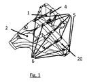
図1は、従来技術で既に知られているギヤハウジングであって、第1のギヤハウジング部1と第2のギヤハウジング部2とで構成されるギヤハウジングを図示している。ギヤハウジング部1および2を連結するために、ねじ付きのねじドーム6が使用される。特に衝突したときのリスクに備えて、ねじ付きのねじドーム6をしっかりと固定するために、この拡張材の領域には、保護リブとしてリブ5が形成される。また、これらの保護リブは更に、ねじまたはダウエルピンを介して直接かつ集中的に伝達されるように力を導く役割を果たし得る。しかしながら、衝突に対する保護機能を果たすために、保護リブの位置を、保護リブの力伝達機能に合わせて自由にまたは最適に選択することはできない。第1のギヤハウジング部1と第2のギヤハウジング部2との間の分離面は、シール20によって封止される。
FIG. 1 shows a gear housing that is already known in the prior art and that includes a first
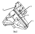
図2は、本発明によるギヤハウジングを図示している。ギヤハウジングは、異なる材料を含み得る第1のギヤハウジング部1と第2のギヤハウジング部2とを備える。第1のギヤハウジング部1は、摩擦攪拌接合連結3によって第2のギヤハウジング部2に永久的に連結される。摩擦攪拌接合連結3は、第1のギヤハウジング部1および第2のギヤハウジング部2と共に、均一な表面を形成する。この連結領域にはシールは不要である。第1のギヤハウジング部1および第2のギヤハウジング部2には、リブ4が、剛性の増加と良好なNVH(騒音・振動・ハーシュネス)特性に最適に寄与するようにして配設される。摩擦攪拌接合連結3の領域には、保護リブは設けられない。
FIG. 2 illustrates a gear housing according to the present invention. The gear housing comprises a first
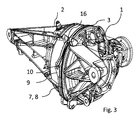
図3は、2つのハウジング部品1および2を有するギヤハウジングの図である。これらハウジング部品は、それぞれのフランジ7、8によって互いに突き合わせ接合される。フランジ連結の箇所において、フランジのうちの一方の領域に径方向の広がり有する厚肉部9が径方向に形成される。この場合では、厚肉部がハウジング部品1のフランジ側に構築されるかハウジング部品2のフランジ側に構築されるかは関係ない。厚肉部内に、排出孔10を確認することができる。2つの部品は、フランジに沿って連続して延びる溶接継ぎ目によって互いに接合される。開始点16で開始して、迅速に回転するピンを備えた摩擦攪拌接合用工具が、フランジ7、8に沿って環状に、次いで、厚肉部の領域に径方向外方に案内される。
FIG. 3 is a diagram of a gear housing having two
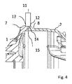
図4は、ギヤハウジング部1、2の接合箇所がどのように構築されるかを断面図で示している。
FIG. 4 is a sectional view showing how the joints of the
ギヤハウジング部は、いずれの場合も、より大きな材料厚さによって構築されるフランジで終端する。それによって、接合箇所に力を均一および均質に導入することができる。フランジの領域において材料厚さを増加させる結果として、互いに対して配置されたときに、接合されるべき間隙15を形成する面が形成される。肩部12、13は、フランジ7、8の外側に形成される。摩擦攪拌接合用工具11の下側当接部材14は、これらの肩部12、13に当接する。摩擦攪拌接合による接合作業のために肩部を予め加工する必要はない。これら肩部は、鋳造部品の未加工表面を備えてもよい。摩擦攪拌接合は、この場合、数ミリメートルまでの粗さ、より良好な品質では1.5mmまでの粗さを許容することができる。それによって、加工ステップを省略することができ、かつ接合工程を鋳造部品に直接使用することができる。技術的な製造理由により常に製造される鋳造部品の外皮もまた、工具の可塑化および混合作用による摩擦攪拌接合作業中に金属マトリックスに均質に組み込まれるので問題ではない。間隙15を画定する表面もまた、粗くかつ未加工であってもよい。この場合では、摩擦攪拌接合はまた、数ミリメートルの間隙を許容するが、確実には1ミリメートルまでの間隙を許容する。
The gear housing part in each case terminates with a flange constructed with a larger material thickness. Thereby, force can be introduced uniformly and homogeneously at the joint. As a result of increasing the material thickness in the region of the flange, a surface is formed that forms a
接合工程では、ダウエルピンを用いて、ギヤハウジング部1および2を互いに対して位置決めすることができる。
In the joining process, the
次に、摩擦攪拌接合用工具が位置決めされ、かつ肩部が位置決めされるときに加工物の表面に挿入される工具のピンが、フランジラインに沿って案内される。この場合では、開始点が過剰接合され、工具が既存の溶接継ぎ目に沿って360°を超えて更に数度の角度だけ案内される。この場合では、工具は厚肉部9に向かう方向に外方にゆっくりと案内される。接合作業は、マンドレルが持ち上げられかつ排出孔が残されるその箇所で終了する。
Next, the pin of the tool that is inserted into the surface of the workpiece when the friction stir welding tool is positioned and the shoulder is positioned is guided along the flange line. In this case, the starting point is over-joined and the tool is guided along the existing weld seam by more than 360 ° and an angle of a few more degrees. In this case, the tool is slowly guided outward in the direction toward the
環状の溶接部の外側の画定された箇所に排出孔が作製されることの結果として、溶接部が不浸透性のままである。 As a result of the creation of discharge holes at defined locations outside the annular weld, the weld remains impermeable.
1 第1のギヤハウジング部
2 第2のギヤハウジング部
3 摩擦攪拌接合連結
4 リブ
5 リブ
6 ねじ付きのねじドーム
7 フランジハウジング部1
8 フランジハウジング部2
9 厚肉部
10 排出孔
11 摩擦攪拌接合用工具
12 肩フランジ8
13 肩フランジ7
14 下側当接部材(工具肩部)
15 間隙
16 開始点
20 シール
DESCRIPTION OF
8
9
13
14 Lower contact member (tool shoulder)
15
Claims (14)
前記第1のギヤハウジング部(1)と前記第2のギヤハウジング部(2)との間の永久的連結が、摩擦攪拌接合連結(3)によって提供され、
前記第1のギヤハウジング部(1)にある第1のフランジ(7)と前記第2のギヤハウジング部(2)にある第2のフランジ(8)とを有するフランジ(7、8)によって、前記第1のギヤハウジング部(1)と前記第2のギヤハウジング部(2)とが突き合わせ連結され、
前記第1と第2のハウジング部(1、2)の一方には、そのフランジ(7、8)の領域に径方向厚肉部(9)が設けられ、
前記摩擦攪拌接合連結(3)はその領域が、360°よりも大きな角度にわたって環状に形成され、
前記径方向厚肉部(9)は、前記摩擦攪拌接合連結(3)の領域のうち前記360°を超えた延長部分を画定するように構成される、
ギヤハウジング。 A first gear housing part (1) and a second gear housing part (2) are provided, and the first gear housing part (1) and the second gear housing part (2) are permanently connected. A vehicle gear housing comprising:
A permanent connection between the first gear housing part (1) and the second gear housing part (2) is provided by a friction stir welding connection (3);
By a flange (7,8) having a first gear housing portion second flange (8) in said first flange (7) in (1) the second gear housing part (2), The first gear housing part (1) and the second gear housing part (2) are connected to each other;
One of the first and second housing parts (1, 2) is provided with a radially thick part (9) in the area of its flange (7, 8),
The friction stir weld connection (3) is formed in an annular shape over an angle greater than 360 °,
The radial thick section (9) is configured to define an extension of the region of the friction stir weld connection (3) beyond the 360 °.
Gear housing.
前記第1のギヤハウジング部(1)および前記第2のギヤハウジング部(2)を準備し、次に、
前記第1のギヤハウジング部(1)と前記第2のギヤハウジング部(2)とを永久的に連結する工程を有し、
摩擦攪拌接合を実施することによって、前記第1のギヤハウジング部(1)と前記第2のギヤハウジング部(2)との間の永久的な連結を構成する摩擦攪拌接合連結(3)がなされ、
前記第1のギヤハウジング部(1)にある第1のフランジ(7)と前記第2のギヤハウジング部(2)にある第2のフランジ(8)とを有するフランジ(7、8)によって、前記第1のギヤハウジング部(1)と前記第2のギヤハウジング部(2)とが突き合わされて位置決めされ、摩擦攪拌接合用工具(11)の肩部が前記フランジの未加工の外側肩部(12、13)上に位置する状態で摩擦攪拌接合用工具(11)が位置決めされ、
前記第1と第2のギヤハウジング部(1、2)の一方には、そのフランジ(7、8)の領域に径方向厚肉部(9)が設けられ、
前記摩擦攪拌接合連結(3)はその領域が、360°よりも大きな角度にわたって環状に形成され、
前記径方向厚肉部(9)は、前記摩擦攪拌接合連結(3)の領域のうち前記360°を超えた延長部分を画定する、
ギヤハウジングの製造方法。 A vehicle gear housing manufacturing method comprising a first gear housing part (1) and a second gear housing part (2),
Preparing the first gear housing part (1) and the second gear housing part (2);
The step of permanently connecting the first gear housing part (1) and the second gear housing part (2);
By performing the friction stir welding, the friction stir welding connection (3) constituting a permanent connection between the first gear housing part (1) and the second gear housing part (2) is made. ,
By a flange (7,8) having a first gear housing portion second flange (8) in said first flange (7) in (1) the second gear housing part (2), The first gear housing part (1) and the second gear housing part (2) are abutted and positioned, and the shoulder of the friction stir welding tool (11) is the unprocessed outer shoulder of the flange. The friction stir welding tool (11) is positioned in a state of being positioned on (12, 13),
One of the first and second gear housing parts (1, 2) is provided with a radial thick part (9) in the region of its flange (7, 8),
The friction stir weld connection (3) is formed in an annular shape over an angle greater than 360 °,
The radial thick section (9) defines an extension of the region of the friction stir weld connection (3) beyond the 360 °;
Manufacturing method of gear housing.
Applications Claiming Priority (3)
| Application Number | Priority Date | Filing Date | Title |
|---|---|---|---|
| DE102013202952.7 | 2013-02-22 | ||
| DE102013202952 | 2013-02-22 | ||
| PCT/EP2014/051214 WO2014127950A1 (en) | 2013-02-22 | 2014-01-22 | Gearbox housing and method for producing a gearbox housing |
Publications (2)
| Publication Number | Publication Date |
|---|---|
| JP2016509178A JP2016509178A (en) | 2016-03-24 |
| JP6207635B2 true JP6207635B2 (en) | 2017-10-04 |
Family
ID=50000976
Family Applications (1)
| Application Number | Title | Priority Date | Filing Date |
|---|---|---|---|
| JP2015558383A Active JP6207635B2 (en) | 2013-02-22 | 2014-01-22 | Gear box housing and manufacturing method of gear box housing |
Country Status (7)
| Country | Link |
|---|---|
| US (1) | US20150377338A1 (en) |
| JP (1) | JP6207635B2 (en) |
| KR (1) | KR20150110655A (en) |
| CN (1) | CN105026795B (en) |
| DE (1) | DE112014000942A5 (en) |
| MX (1) | MX2015010929A (en) |
| WO (1) | WO2014127950A1 (en) |
Families Citing this family (9)
| Publication number | Priority date | Publication date | Assignee | Title |
|---|---|---|---|---|
| DE102016209549A1 (en) * | 2016-06-01 | 2017-12-07 | Voith Patent Gmbh | Spur gears |
| DE102017209979A1 (en) * | 2017-06-13 | 2018-12-13 | Zf Friedrichshafen Ag | Method for producing a gear housing part with an oil bunker, transmission housing part with oil bunker and gear device |
| CN111250860A (en) * | 2018-11-30 | 2020-06-09 | 华孚精密科技(马鞍山)有限公司 | Manufacturing method of large-size die-casting product |
| DE102019210828A1 (en) * | 2019-07-22 | 2021-01-28 | Audi Ag | Friction stir welding a workpiece |
| DE102019219128A1 (en) * | 2019-12-09 | 2021-06-10 | Zf Friedrichshafen Ag | Drive unit for an industrial truck, modular system for assembling a drive unit for an industrial truck, industrial truck and method for assembling a drive unit for an industrial truck |
| DE102019220326A1 (en) * | 2019-12-20 | 2021-06-24 | Robert Bosch Gmbh | Method for producing a hydraulic housing, hydraulic housing |
| JP7472623B2 (en) * | 2020-04-21 | 2024-04-23 | 株式会社アイシン | Aluminum case and method for manufacturing the aluminum case |
| EP4303049A1 (en) * | 2022-07-05 | 2024-01-10 | Volvo Car Corporation | Motor and transmission assembly for a vehicle |
| TWM653802U (en) * | 2024-01-03 | 2024-04-01 | 惠朋國際股份有限公司 | Brake caliper housing suitable for friction stir welding |
Family Cites Families (19)
| Publication number | Priority date | Publication date | Assignee | Title |
|---|---|---|---|---|
| AT11066B (en) * | 1899-09-28 | 1903-03-10 | Emil Dr Bronnert | Process for the production of high-percentage solutions of cellulose in chlorzinc solutions. |
| US5203221A (en) * | 1991-10-15 | 1993-04-20 | The Falk Corporation | Shaft mountable gear drive |
| US5484332A (en) * | 1992-08-28 | 1996-01-16 | Rhone-Poulenc Inc. | Poultry washing apparatus and method |
| DE4317073A1 (en) * | 1993-05-21 | 1994-11-24 | Porsche Ag | Differential housing for the axle drive of a motor vehicle |
| US5431325A (en) * | 1993-12-27 | 1995-07-11 | Ford Motor Company | Method and apparatus for producing hermetic torque converter seam |
| DE19615007A1 (en) * | 1996-04-16 | 1997-10-23 | Mekra Lang Gmbh & Co Kg | Gear unit |
| JP3897391B2 (en) * | 1997-03-25 | 2007-03-22 | 昭和電工株式会社 | Friction stir welding method for metal joining members |
| DE19905625A1 (en) * | 1998-02-17 | 1999-08-19 | Luk Getriebe Systeme Gmbh | Hydraulic power transmission system using polymer coated housing rear |
| JP2000176581A (en) * | 1998-12-09 | 2000-06-27 | Tokai Rubber Ind Ltd | Method for manufacturing arm member |
| JP4558173B2 (en) * | 2000-10-23 | 2010-10-06 | 住友軽金属工業株式会社 | Aluminum material joining method and aluminum material joining product |
| DE102006008239A1 (en) * | 2006-02-22 | 2007-08-23 | Volkswagen Ag | Process to manufacture two-part automotive gearbox housing linked at butt weld seam with raised lips |
| JP4828255B2 (en) * | 2006-02-24 | 2011-11-30 | 日立オートモティブシステムズ株式会社 | Disc brake |
| US20080053700A1 (en) * | 2006-09-06 | 2008-03-06 | O'connor Kurt F | Sealed electronic component |
| JP5003287B2 (en) * | 2006-09-14 | 2012-08-15 | 日産自動車株式会社 | Container joint structure, torque converter case joint structure, and container joint method |
| DE102007053516A1 (en) | 2007-11-09 | 2009-05-14 | Bayerische Motoren Werke Aktiengesellschaft | Gear casing for e.g. axle gear, of vehicle, has two gear casing parts connected with one another by additional connecting material such as welding wire, solder or adhesive, in detachable or firmly bonded manner |
| JP2009274117A (en) * | 2008-05-15 | 2009-11-26 | Nippon Light Metal Co Ltd | Friction stir welding method for member having hollow part |
| AT11066U1 (en) * | 2008-11-28 | 2010-04-15 | Alutech Gmbh | PRESSURE TANK |
| JP5221411B2 (en) * | 2009-02-19 | 2013-06-26 | 本田技研工業株式会社 | Joining control method of friction stir welding |
| JP5136516B2 (en) * | 2009-06-02 | 2013-02-06 | 日本軽金属株式会社 | Manufacturing method of sealed container |
-
2014
- 2014-01-22 JP JP2015558383A patent/JP6207635B2/en active Active
- 2014-01-22 DE DE112014000942.3T patent/DE112014000942A5/en active Pending
- 2014-01-22 KR KR1020157022355A patent/KR20150110655A/en not_active Ceased
- 2014-01-22 MX MX2015010929A patent/MX2015010929A/en unknown
- 2014-01-22 US US14/768,019 patent/US20150377338A1/en not_active Abandoned
- 2014-01-22 WO PCT/EP2014/051214 patent/WO2014127950A1/en not_active Ceased
- 2014-01-22 CN CN201480009723.6A patent/CN105026795B/en active Active
Also Published As
| Publication number | Publication date |
|---|---|
| WO2014127950A1 (en) | 2014-08-28 |
| US20150377338A1 (en) | 2015-12-31 |
| JP2016509178A (en) | 2016-03-24 |
| MX2015010929A (en) | 2017-05-01 |
| CN105026795A (en) | 2015-11-04 |
| KR20150110655A (en) | 2015-10-02 |
| DE112014000942A5 (en) | 2015-12-10 |
| CN105026795B (en) | 2017-06-23 |
Similar Documents
| Publication | Publication Date | Title |
|---|---|---|
| JP2016509178A (en) | Gear box housing and manufacturing method of gear box housing | |
| JP5614054B2 (en) | Beam welding member and differential device provided with the same | |
| JP6322306B2 (en) | Method for manufacturing aluminum structural member | |
| JP2011167746A (en) | Beam-welded member and differential gear equipped with the same | |
| US11806801B2 (en) | Joining method | |
| JPWO2009084136A1 (en) | Dissimilar material joint structure, tank skirt having the dissimilar material joint structure, transport ship having the tank skirt, and dissimilar metal member joining method | |
| US20140083191A1 (en) | Joint structure by welding and welding quality inspection method thereof | |
| KR20160098192A (en) | Production method for fluid coupling and fluid coupling | |
| JP2013542380A (en) | Flanged bearing ring and method for manufacturing the flanged bearing ring | |
| JP4751625B2 (en) | Formation method of welded joint | |
| JP6071132B2 (en) | Zygote | |
| JP5915802B2 (en) | Friction stir welding method | |
| JP2010253534A (en) | Member with built-in cooling path and method of manufacturing the same | |
| KR20140087406A (en) | Friction stir welding tool | |
| KR20130068260A (en) | A method for welding a motor case by friction stir welding, and a motor case manufactured by the same | |
| JP2020059041A (en) | Dissimilar material joining method, dissimilar material joint, tubular member with dissimilar material joining auxiliary member and manufacturing method thereof | |
| JP6756105B2 (en) | Joining method | |
| JP2009279595A (en) | Joining method | |
| KR101973745B1 (en) | A method for manufacturing yoke | |
| JP6095435B2 (en) | Indexing table | |
| EP2326456B1 (en) | Method of manufacturing by laser welding a vehicle axle | |
| JP2007283348A (en) | Welding method and ring gear member welded thereby | |
| JP6164337B2 (en) | Friction stir welding method | |
| JP2016182617A (en) | Mold for enlargement processing | |
| JP4543668B2 (en) | Hydraulic forming pipe and automotive structural member |
Legal Events
| Date | Code | Title | Description |
|---|---|---|---|
| A621 | Written request for application examination |
Free format text: JAPANESE INTERMEDIATE CODE: A621 Effective date: 20151008 |
|
| A977 | Report on retrieval |
Free format text: JAPANESE INTERMEDIATE CODE: A971007 Effective date: 20160902 |
|
| A131 | Notification of reasons for refusal |
Free format text: JAPANESE INTERMEDIATE CODE: A131 Effective date: 20160920 |
|
| A521 | Request for written amendment filed |
Free format text: JAPANESE INTERMEDIATE CODE: A523 Effective date: 20161109 |
|
| A521 | Request for written amendment filed |
Free format text: JAPANESE INTERMEDIATE CODE: A523 Effective date: 20161110 |
|
| A131 | Notification of reasons for refusal |
Free format text: JAPANESE INTERMEDIATE CODE: A131 Effective date: 20170411 |
|
| A521 | Request for written amendment filed |
Free format text: JAPANESE INTERMEDIATE CODE: A523 Effective date: 20170414 |
|
| TRDD | Decision of grant or rejection written | ||
| A01 | Written decision to grant a patent or to grant a registration (utility model) |
Free format text: JAPANESE INTERMEDIATE CODE: A01 Effective date: 20170808 |
|
| A61 | First payment of annual fees (during grant procedure) |
Free format text: JAPANESE INTERMEDIATE CODE: A61 Effective date: 20170905 |
|
| R150 | Certificate of patent or registration of utility model |
Ref document number: 6207635 Country of ref document: JP Free format text: JAPANESE INTERMEDIATE CODE: R150 |
|
| R250 | Receipt of annual fees |
Free format text: JAPANESE INTERMEDIATE CODE: R250 |
|
| R250 | Receipt of annual fees |
Free format text: JAPANESE INTERMEDIATE CODE: R250 |
|
| R250 | Receipt of annual fees |
Free format text: JAPANESE INTERMEDIATE CODE: R250 |
|
| R250 | Receipt of annual fees |
Free format text: JAPANESE INTERMEDIATE CODE: R250 |
|
| R250 | Receipt of annual fees |
Free format text: JAPANESE INTERMEDIATE CODE: R250 |
|
| R250 | Receipt of annual fees |
Free format text: JAPANESE INTERMEDIATE CODE: R250 |