JP6211237B1 - Laser equipment - Google Patents
Laser equipment Download PDFInfo
- Publication number
- JP6211237B1 JP6211237B1 JP2017533509A JP2017533509A JP6211237B1 JP 6211237 B1 JP6211237 B1 JP 6211237B1 JP 2017533509 A JP2017533509 A JP 2017533509A JP 2017533509 A JP2017533509 A JP 2017533509A JP 6211237 B1 JP6211237 B1 JP 6211237B1
- Authority
- JP
- Japan
- Prior art keywords
- laser
- diffracted light
- order diffracted
- beams
- dispersive element
- Prior art date
- Legal status (The legal status is an assumption and is not a legal conclusion. Google has not performed a legal analysis and makes no representation as to the accuracy of the status listed.)
- Active
Links
Images


Classifications
-
- H—ELECTRICITY
- H01—ELECTRIC ELEMENTS
- H01S—DEVICES USING THE PROCESS OF LIGHT AMPLIFICATION BY STIMULATED EMISSION OF RADIATION [LASER] TO AMPLIFY OR GENERATE LIGHT; DEVICES USING STIMULATED EMISSION OF ELECTROMAGNETIC RADIATION IN WAVE RANGES OTHER THAN OPTICAL
- H01S5/00—Semiconductor lasers
- H01S5/10—Construction or shape of the optical resonator, e.g. extended or external cavity, coupled cavities, bent-guide, varying width, thickness or composition of the active region
- H01S5/14—External cavity lasers
- H01S5/141—External cavity lasers using a wavelength selective device, e.g. a grating or etalon
-
- H—ELECTRICITY
- H01—ELECTRIC ELEMENTS
- H01S—DEVICES USING THE PROCESS OF LIGHT AMPLIFICATION BY STIMULATED EMISSION OF RADIATION [LASER] TO AMPLIFY OR GENERATE LIGHT; DEVICES USING STIMULATED EMISSION OF ELECTROMAGNETIC RADIATION IN WAVE RANGES OTHER THAN OPTICAL
- H01S5/00—Semiconductor lasers
- H01S5/40—Arrangement of two or more semiconductor lasers, not provided for in groups H01S5/02 - H01S5/30
- H01S5/4012—Beam combining, e.g. by the use of fibres, gratings, polarisers, prisms
-
- H—ELECTRICITY
- H01—ELECTRIC ELEMENTS
- H01S—DEVICES USING THE PROCESS OF LIGHT AMPLIFICATION BY STIMULATED EMISSION OF RADIATION [LASER] TO AMPLIFY OR GENERATE LIGHT; DEVICES USING STIMULATED EMISSION OF ELECTROMAGNETIC RADIATION IN WAVE RANGES OTHER THAN OPTICAL
- H01S5/00—Semiconductor lasers
- H01S5/40—Arrangement of two or more semiconductor lasers, not provided for in groups H01S5/02 - H01S5/30
- H01S5/4025—Array arrangements, e.g. constituted by discrete laser diodes or laser bar
- H01S5/4087—Array arrangements, e.g. constituted by discrete laser diodes or laser bar emitting more than one wavelength
-
- H—ELECTRICITY
- H01—ELECTRIC ELEMENTS
- H01S—DEVICES USING THE PROCESS OF LIGHT AMPLIFICATION BY STIMULATED EMISSION OF RADIATION [LASER] TO AMPLIFY OR GENERATE LIGHT; DEVICES USING STIMULATED EMISSION OF ELECTROMAGNETIC RADIATION IN WAVE RANGES OTHER THAN OPTICAL
- H01S5/00—Semiconductor lasers
- H01S5/02—Structural details or components not essential to laser action
- H01S5/028—Coatings ; Treatment of the laser facets, e.g. etching, passivation layers or reflecting layers
- H01S5/0287—Facet reflectivity
-
- H—ELECTRICITY
- H01—ELECTRIC ELEMENTS
- H01S—DEVICES USING THE PROCESS OF LIGHT AMPLIFICATION BY STIMULATED EMISSION OF RADIATION [LASER] TO AMPLIFY OR GENERATE LIGHT; DEVICES USING STIMULATED EMISSION OF ELECTROMAGNETIC RADIATION IN WAVE RANGES OTHER THAN OPTICAL
- H01S5/00—Semiconductor lasers
- H01S5/40—Arrangement of two or more semiconductor lasers, not provided for in groups H01S5/02 - H01S5/30
- H01S5/4025—Array arrangements, e.g. constituted by discrete laser diodes or laser bar
Landscapes
- Physics & Mathematics (AREA)
- Condensed Matter Physics & Semiconductors (AREA)
- General Physics & Mathematics (AREA)
- Electromagnetism (AREA)
- Optics & Photonics (AREA)
- Semiconductor Lasers (AREA)
Abstract
互いに波長の異なるレーザビームを発生する複数のレーザ媒質(11)と、複数のレーザ媒質(11)のそれぞれから出射されるレ−ザビームを重畳レンズ(2)により分散素子(3)上に1つに重畳させて結合するレーザ装置(100−1)であって、分散素子(3)は、重畳レンズ(2)により複数のレーザビームが1つに重畳された位置に設置されると共に、複数のレーザビームの一部を第1のレーザビームとしてレーザ媒質(11)側へ戻し、複数のレーザビームの一部を1つの光軸を有する第2のレーザビームとして出力する。A plurality of laser media (11) for generating laser beams having different wavelengths from each other, and a laser beam emitted from each of the plurality of laser media (11) on the dispersive element (3) by the superimposing lens (2). The dispersive element (3) is installed at a position where a plurality of laser beams are superimposed on one by the superimposing lens (2), and is coupled to the laser device (100-1). A part of the laser beam is returned to the laser medium (11) side as a first laser beam, and a part of the plurality of laser beams is output as a second laser beam having one optical axis.
Description
本発明は、波長の異なる複数のレーザビームを結合することによって高出力のレーザビームを得る波長ビーム結合型のレーザ装置に関する。 The present invention relates to a wavelength beam combining type laser apparatus that obtains a high-power laser beam by combining a plurality of laser beams having different wavelengths.
特許文献1に開示される従来のレーザ装置は、波長の異なる複数のレーザビームを、回折格子である分散素子上に重畳し、分散作用によって1本に結合したレーザビームを生成し、部分反射鏡を用いてこの結合したレーザビームの一部を反射してレーザ媒質へ戻して共振器を構成すると共に、結合したレーザビームの部分反射鏡を透過する成分を出力として取り出すように構成される。
The conventional laser device disclosed in
しかしながら特許文献1に開示される従来のレーザ装置では、結合したレーザビームの一部が反射してレーザ媒質側へ戻る際にレーザビームが分散素子を経由するために、分散素子の損失によってビーム出力が低下すると共にエネルギー効率が低下するという課題があった。
However, in the conventional laser device disclosed in
本発明は、上記に鑑みてなされたものであって、ビーム出力及びエネルギー効率の低下を抑制できるレーザ装置を得ることを目的とする。 The present invention has been made in view of the above, and an object of the present invention is to obtain a laser apparatus capable of suppressing a decrease in beam output and energy efficiency.
上述した課題を解決し、目的を達成するために、本発明のレーザ装置は、互いに波長の異なるレーザビームを発生する複数のレーザ媒質と、複数のレーザ媒質のそれぞれから出射されるレ−ザビームを重畳手段により分散素子上に1つに重畳させて結合するレーザ装置であって、分散素子は、重畳手段により複数のレーザビームが1つに重畳された位置に設置されると共に、互いに波長の異なるレーザビームの2次回折光をそれぞれのレーザ媒質へ帰還させ、互いに波長の異なるレーザビームの+1次回折光及び−1次回折光を1つの光軸を有するレーザビームとして出力することを特徴とする。 In order to solve the above-described problems and achieve the object, a laser apparatus according to the present invention includes a plurality of laser media that generate laser beams having different wavelengths, and a laser beam emitted from each of the plurality of laser media. A laser device that is superposed and coupled together on a dispersive element by a superimposing means, wherein the dispersive element is installed at a position where a plurality of laser beams are superposed on one by the superimposing means and have different wavelengths from each other The second-order diffracted light of the laser beam is fed back to each laser medium, and the + 1st-order diffracted light and the −1st-order diffracted light of laser beams having different wavelengths are output as laser beams having one optical axis .
本発明に係るレーザ装置は、ビーム出力及びエネルギー効率の低下を抑制できるという効果を奏する。 The laser device according to the present invention has an effect of suppressing a decrease in beam output and energy efficiency.
以下に、本発明の実施の形態に係るレーザ装置を図面に基づいて詳細に説明する。なお、この実施の形態によりこの発明が限定されるものではない。 Hereinafter, a laser device according to an embodiment of the present invention will be described in detail with reference to the drawings. Note that the present invention is not limited to the embodiments.
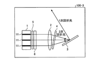
実施の形態1.
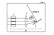
図1は本発明の実施の形態1に係るレーザ装置の構成を示す図である。実施の形態1に係るレーザ装置100−1は、レーザユニット1と、レーザユニット1の出射側に配置された分散素子3と、レーザユニット1及び分散素子3の間に配置された重畳手段である重畳レンズ2とを備える。分散素子3は、重畳レンズ2により、複数のレーザビームが1つに重畳された位置に設置されると共に、複数のレーザビームの一部を第1のレーザビームとしてレーザ媒質11側へ戻し、複数のレーザビームの一部を1つの光軸を有する第2のレーザビームとして出力する。
FIG. 1 is a diagram showing a configuration of a laser apparatus according to
レーザユニット1としては半導体レーザアレイまたは半導体レーザバーを例示できる。レーザ媒質11としては半導体レーザアレイを例示できる。半導体レーザバーは、複数の発光点の形成された一枚の半導体チップで形成されたデバイスであり、半導体レーザアレイは、複数の半導体チップを一つのデバイスに組み込んだものである。半導体レーザバーが半導体レーザアレイに含まれる場合もある。複数のレーザ媒質11のそれぞれが発生したレーザビームは、重畳レンズ2によって偏向され、各々に異なる出射角度が付与されて分散素子3上において重畳される。
As the
分散素子3としては回折格子を例示でき、レーザ装置100−1では分散素子3が所謂、リトロー配置されている。リトロー配置とは、想定される波長において複数のレーザビームのそれぞれの2次回折光の回折角と複数のレーザビームのそれぞれの入射角とが一致するように、回折格子の溝本数及び設置角度が設定されている配置を指す。リトロー配置された回折格子を備えるレーザ装置100−1では、回折格子で発生する2次回折光が入射ビームに沿ってそれぞれのレーザ媒質11に帰還するフィードバック光となり、それぞれのレーザ媒質11と回折格子との間でビーム毎に各々異なる波長で動作する共振器50が構成される。
An example of the
回折格子の入射角θと回折格子の回折角φとレーザビームの波長λとの関係は、(1)式のグレーティング方程式で与えられる。(1)式において、dは回折格子の周期を表し、mは回折次数を表す。 The relationship between the incident angle θ of the diffraction grating, the diffraction angle φ of the diffraction grating, and the wavelength λ of the laser beam is given by the grating equation (1). In the formula (1), d represents the period of the diffraction grating, and m represents the diffraction order.
![]()
![]()
リトロー動作時の2次回折光(回折次数m=2)においては、2次回折光の回折角をφ2とし、回折格子の入射角をθinとしたとき、(2)式が成立する。リトロー動作とは、2次回折光に対してリトロー配置された回折格子で発生する2次回折光がレーザ媒質11へ帰還する動作である。For the second-order diffracted light (diffraction order m = 2) during the Littrow operation, equation (2) is established when the diffraction angle of the second-order diffracted light is φ 2 and the incident angle of the diffraction grating is θ in . The Littrow operation is an operation in which the second-order diffracted light generated by the diffraction grating arranged in a Littrow arrangement with respect to the second-order diffracted light returns to the
![]()
![]()
また(3)式のように2次回折光の回折角φ2が回折格子の入射角θinと等しいとき、2次回折光の回折角φ2は(4)式により表される。The (3) when the diffraction angle phi 2 of the second-order diffracted light is equal to the incident angle theta in the diffraction grating as in Equation diffraction angle phi 2 of the second-order diffracted light is expressed by equation (4).
![]()
![]()

このとき2次回折光と同時に発生する1次回折光の回折角φ1は(5)式により表される。すなわち1次回折光の回折角φ1はレーザビームの波長λに依らずφ1=0となる。At this time, the diffraction angle φ 1 of the first-order diffracted light generated simultaneously with the second-order diffracted light is expressed by the equation (5). That is, the diffraction angle φ 1 of the first-order diffracted light is φ 1 = 0 regardless of the wavelength λ of the laser beam.
上記の解析結果によれば、実施の形態1に係るレーザ装置100−1の動作時に、波長の異なる複数のレーザビームの1次回折光の全てが、波長に依らずに回折格子面に対して直角方向に出力される。これにより同軸上に方向の揃った1本の結合された出力ビームを得ることができる。 According to the above analysis results, during the operation of the laser apparatus 100-1 according to the first embodiment, all of the first-order diffracted lights of a plurality of laser beams having different wavelengths are perpendicular to the diffraction grating plane regardless of the wavelengths. Output in the direction. As a result, one combined output beam having the same direction on the same axis can be obtained.
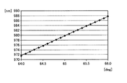
次にレーザ装置100−1の動作を説明する。図2は本発明の実施の形態1に係るレーザ装置において、2次回折光がレーザ媒質へ帰還する際の各レーザビームの波長を示す図である。図2の横軸は分散素子3へ入射する複数のレーザビームのそれぞれの入射角を表し、図2の縦軸は分散素子3へ入射する複数のレーザビームのそれぞれの波長を表す。図2には、回折格子への入射角が64.0[deg]〜66.0[deg]となるように配置された複数のレーザ媒質11から出力されるレーザビームが925[line/mm]の回折格子に重畳されたときに、2次回折光に対してリトロー配置された回折格子で発生する2次回折光がレーザ媒質11へ帰還する際の各レーザビームの波長が示される。
Next, the operation of the laser device 100-1 will be described. FIG. 2 is a diagram showing the wavelength of each laser beam when the second-order diffracted light returns to the laser medium in the laser apparatus according to
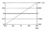
図3は2次回折光に対してリトロー配置された回折格子で発生する1次回折光の回折角を示す図である。図3の横軸は分散素子3へ入射する複数のレーザビームのそれぞれの入射角[deg]を表し、図3の縦軸は1次回折光の回折角φ1を表す。図3には、回折格子への入射角が64.0[deg]〜66.0[deg]となるように配置された複数のレーザ媒質11から出力されるレーザビームが925[line/mm]の回折格子に重畳されたとき、2次回折光に対してリトロー配置された回折格子で発生する1次回折光の回折角φ1が示される。実線は1次回折光に対する回折角を表し、点線は2次回折光に対する回折角を表す。FIG. 3 is a diagram showing the diffraction angle of the first-order diffracted light generated by the diffraction grating arranged in the Littrow arrangement with respect to the second-order diffracted light. 3 represents the incident angle [deg] of each of the plurality of laser beams incident on the
レーザ装置100−1の共振器50では、複数のレーザ媒質11のそれぞれで発生したレーザビームの2次回折光が複数のレーザ媒質11のそれぞれにフィードバックされる。これにより複数のレーザ媒質11のそれぞれは、図2に示す980[nm]近くの波長で発振する。このとき図3に示すように、1次回折光の回折角φ1は、64〜66[deg]に配置された全てのレーザ媒質11に対して0[deg]となり、1本に結合した出力ビームが得られる。In the
以下では、特許文献1に開示されるレーザ装置と実施の形態1に係るレーザ装置100−1とを比較して、レーザ装置100−1の効果を説明する。
Hereinafter, the effects of the laser device 100-1 will be described by comparing the laser device disclosed in
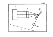
図4は特許文献1に開示されるレーザ装置の構成を示す図である。特許文献1に開示されるレーザ装置100Aは、レーザユニット1、重畳レンズ2、分散素子31及び部分反射鏡40を備える。レーザユニット1、重畳レンズ2、分散素子31及び部分反射鏡40は共振器51を構成する。
FIG. 4 is a diagram showing the configuration of the laser device disclosed in
レーザ装置100Aでは、レーザユニット1が備える複数のレーザ媒質のそれぞれから発生するレーザビームを1本に束ねた結合ビームが出力される。またレーザ装置100Aでは、複数のレーザビームのそれぞれを分散素子31が振り分けてフィードバックすることによって、共振器51が正常に動作するための波長に関する情報が得られる。これにより複数のレーザビームのそれぞれの波長が決定される。
In the
レーザ装置100Aでは、損失を伴う分散素子31が共振器51内に配置されるため、共振器51内にレーザビームが繰り返し伝搬される際に分散素子31の損失の影響を受けて、ビーム出力が低下すると共にエネルギー効率が低下する。またレーザ装置100Aは、共振器51を構成する部分反射鏡40及び分散素子31という複数の光学素子を備えるため、アライメントを必要とする要素が多くなり、ビーム出力が不安定になり易い。
In the
これに対して実施の形態1に係るレーザ装置100−1は、複数のレーザ媒質11のそれぞれから発生するレーザビームを元のレーザ媒質11へフィードバックする作用を有する再帰反射器として、分散素子3の2次回折を割り当てることにより、複数のレーザビームのそれぞれの波長が決定される。また実施の形態1に係るレーザ装置100−1では、このとき同時に発生する1次回折光の回折角φ1が全て0[deg]となる性質を利用して1本に束ねられた結合ビーム出力が得られる。On the other hand, the laser device 100-1 according to the first embodiment is a retroreflector having a function of feeding back the laser beam generated from each of the plurality of
このような機能及び作用により、実施の形態1に係るレーザ装置100−1では、分散素子3の損失が共振器50端に限定され、共振器50内の損失が無くなり、分散素子3の損失に起因するビーム出力の低下とエネルギー効率の低下とが最小限に抑えられる。
With such a function and action, in the laser device 100-1 according to the first embodiment, the loss of the
また実施の形態1に係るレーザ装置100−1では、1枚の分散素子3で波長の決定及び結合を同時に行うことができるため、図4に示す部分反射鏡40が不要となり、ビーム出力が不安定となる要因を減らすことができる。
Further, in the laser apparatus 100-1 according to the first embodiment, the wavelength can be determined and combined at the same time with one
なお図4に示されるレーザ装置100Aは共振器内部波長結合方式を用いたレーザ装置であるのに対して、実施の形態1に係るレーザ装置100−1は、共振器端部波長結合方式という新しい方式を用いたレーザ装置である。レーザ装置100Aは、レーザビームが繰り返し伝搬される際の損失の影響がある。実施の形態1に係るレーザ装置100−1によれば、レーザ装置100Aとは異なり、光学動作に無駄が無く、高いビーム出力及びエネルギー効率が得られる。また光学素子である部分反射鏡40が不要であるため、ビーム出力を安定させることができる。
4 is a laser device using the resonator internal wavelength coupling method, the laser device 100-1 according to the first embodiment is a new resonator end wavelength coupling method. This is a laser device using the method. The
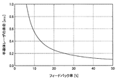
また実施の形態1に係るレーザ装置100−1は、レーザユニット1の射出面に設けられたへき界面よりも反射率を下げる減反射コーティングを施した半導体レーザの外部共振器に適用できる。減反射コーティングはレーザユニット1の射出面に設けられている。ゲインの高い半導体レーザの場合、高いスロープ効率を得やすい低いフィードバック率の方が高出力を得ることができる。低いフィードバック率とは、1次回折光に対して2次回折光の回折効率が低いことを示す。またフィードバック率が高い場合、半導体レーザの寿命が短くなることが報告されており、明確な波長決定をできる範囲ではフィードバック率が低い方が好ましい。実施の形態1に係るレーザ装置100−1は、第1のレーザビームとしてレーザ媒質側へ戻る割合を10%以下とすることで、エネルギー効率を高めることができると共に、装置の寿命を長くすることができる。
The laser device 100-1 according to the first embodiment can be applied to an external resonator of a semiconductor laser provided with a anti-reflection coating that lowers the reflectivity from the detachment interface provided on the emission surface of the
図5はフィードバック率に対する半導体レーザの寿命の関係を示す図である。図5の縦軸は半導体レーザの寿命を表し、図5の横軸は、2次回折光が入射ビームに沿ってそれぞれのレーザ媒質11に帰還するフィードバック率を表す。半導体レーザの寿命は、フィードバック率が高くなるほど減少するため、レーザ装置の寿命の観点からはフィードバック率は低い方が望ましい。図5に示されるフィードバック率に対する半導体レーザの寿命の特性によれば、フィードバック率が10%以上になると、半導体レーザの寿命は、半導体レーザの出射端面を部分反射コーティングして外部共振器なしの半導体レーザとして使用したとき(フィードバック率は数%であるのが一般的)の半分以下となる。従って、フィードバック率を10%以下とするためには、フィードバックを行う分散素子3の2次回折効率を10%以下とすることが望ましい。
FIG. 5 is a graph showing the relationship between the feedback rate and the lifetime of the semiconductor laser. The vertical axis in FIG. 5 represents the lifetime of the semiconductor laser, and the horizontal axis in FIG. 5 represents the feedback rate at which the second-order diffracted light returns to each
一方で、フィードバック率、すなわち外部共振器から半導体レーザへの帰還率を低下させると、半導体レーザの発振波長を外部共振器で制御することが困難となる。半導体レーザの出射面には、前述したように減反射コーティングが設けられるが、0.5%以下の残存反射率が存在する。外部共振器からの帰還率が低下すると、外部発振から半導体レーザ出射面への残存反射率による発振に切り替わるためである。このように半導体レーザの寿命と外部共振器の有効性とはトレードオフの関係にある。これらのトレードオフの関係から、フィードバック率を決定する必要がある。半導体レーザの寿命と外部共振器の有効性とを両立可能なフィードバック率としては2%〜10%が望ましい。 On the other hand, if the feedback rate, that is, the feedback rate from the external resonator to the semiconductor laser is lowered, it becomes difficult to control the oscillation wavelength of the semiconductor laser with the external resonator. As described above, the antireflection coating is provided on the emission surface of the semiconductor laser, but there is a residual reflectance of 0.5% or less. This is because when the feedback factor from the external resonator is reduced, the oscillation is switched from the external oscillation to the oscillation by the residual reflectance to the semiconductor laser emission surface. As described above, the lifetime of the semiconductor laser and the effectiveness of the external resonator are in a trade-off relationship. It is necessary to determine the feedback rate from these trade-off relationships. A feedback rate that can achieve both the life of the semiconductor laser and the effectiveness of the external resonator is preferably 2% to 10%.
またエネルギー効率を高める動作を実現するためには、取り出される1次回折光の出力効率を高くすることが有利である。2次回折光と1次回折光とを同時に発生する分散素子3では、+1次回折光と−1次回折光との両方が発生する。このとき分散素子3が対称な構造であり、分散素子3の+1次回折光及び−1次回折光の発生特性が互いに同一である場合、1次回折効率を50%以上に高めることが困難となり、結果として高効率化の妨げとなる。1次回折効率とは、入射光出力に対する1次回折光出力の割合である。このような課題に対しては、分散素子3にブレースまたは2段以上の溝構造を用いて、第2のレーザビームが分散素子3の+1次回折光及び−1次回折光である場合、分散素子3は、+1次回折光及び−1次回折光の発生特性が互いに異なるように構成される。これにより、分散素子3に入射するレーザビームの1次回折への結合が大きくなり、結果としてエネルギー効率を高める動作が実現できる。
Also, in order to realize an operation for increasing energy efficiency, it is advantageous to increase the output efficiency of the extracted first-order diffracted light. In the
実施の形態2.
図6は本発明の実施の形態2に係るレーザ装置の構成を示す図である。実施の形態2に係るレーザ装置100−2は、レーザユニット1、重畳レンズ2及び分散素子3に加えて、波長フィルタ4を備える。波長フィルタ4は、重畳レンズ2及び分散素子3の間に配置される。波長フィルタ4としては、エタロンまたは薄膜フィルタを例示できる。
FIG. 6 is a diagram showing a configuration of a laser apparatus according to
一般的に回折格子では、リトロー配置での使用において最大の反射率、すなわち最大の回折効率が得られることから、リトロー条件に合致する波長が選択されやすい。ところがその効果だけでは、異なるレーザ媒質間を横断して意図しない波長で発振するため、ビーム品質が低下する現象、所謂クロストーク現象を抑制できない可能性がある。実施の形態2に係るレーザ装置100−2は、損失の小さい波長フィルタ4を用いてクロストーク現象を抑制することによって、高いビーム出力及びエネルギー効率を得ることができ、また高いビーム品質の出力を得ることができる。 Generally, in a diffraction grating, the maximum reflectance, that is, the maximum diffraction efficiency is obtained when used in a Littrow arrangement, and therefore, a wavelength that meets the Littrow condition is easily selected. However, with this effect alone, oscillation occurs at an unintended wavelength across different laser media, so that there is a possibility that the phenomenon of beam quality deterioration, the so-called crosstalk phenomenon, cannot be suppressed. The laser apparatus 100-2 according to the second embodiment can obtain a high beam output and energy efficiency by suppressing the crosstalk phenomenon by using the wavelength filter 4 with a small loss, and can also provide a high beam quality output. Can be obtained.
以下では、一例として米国特許出願公開第2015/0146282号明細書に開示されるレーザ装置と実施の形態2に係るレーザ装置100−2とを比較して、レーザ装置100−2の効果を説明する。以下では、米国特許出願公開第2015/0146282号明細書に開示されるレーザ装置を単に、比較例に係るレーザ装置と称す場合がある。 Hereinafter, as an example, the effect of the laser device 100-2 will be described by comparing the laser device disclosed in US Patent Application Publication No. 2015/0146282 and the laser device 100-2 according to the second embodiment. . Hereinafter, the laser device disclosed in US Patent Application Publication No. 2015/0146282 may be simply referred to as a laser device according to a comparative example.
図7は比較例に係るレーザ装置の構成を示す図である。比較例に係るレーザ装置100Bは、少なくともレーザユニット1、重畳レンズ2及び波長フィルタ60を有する共振器部70と、少なくとも分散素子32を有するビーム結合部80とで構成される。比較例に係るレーザ装置100Bは、共振器外部波長結合方式を用いたレーザ装置であるのに対して、実施の形態2に係るレーザ装置100−2は、共振器端部波長結合方式という新しい方式を用いたレーザ装置である。
FIG. 7 is a diagram showing a configuration of a laser apparatus according to a comparative example. The
比較例に係るレーザ装置100Bの共振器部70では、複数のレーザビームのそれぞれの波長が決定され、ビーム結合部80では1本に結合した出力ビームが得られる。波長フィルタ60及び分散素子32は各々が角度依存性を持つため、共振器部70またはビーム結合部80の角度が変動すると、波長決定特性とビーム結合特性との関係が変化し、結果として出力ビームの品質が変動する。また比較例に係るレーザ装置100Bは、共振器部70及びビーム結合部80を備えるため、共振器部70のみ備える場合に比べて構成が複雑となり、レーザ装置の製造コストが増加する。
The
これに対して実施の形態2に係るレーザ装置100−2は、複数のレーザビームの波長の決定及び結合を1枚の分散素子3で行うため、波長決定特性とビーム結合特性との間の関係がずれることなく、出力ビームの品質が変動することがない。またレーザ装置100−2は、比較例に係るレーザ装置100Bに比べて構成が簡素化され、レーザ装置の製造コストを低減できる。
On the other hand, since the laser device 100-2 according to the second embodiment determines and combines the wavelengths of a plurality of laser beams with one
また比較例に係るレーザ装置100Bで使用される波長フィルタ60では、周期的な複数の波長が選択される可能性があるため、意図しない波長選択を回避するために自由スペクトル領域(Free Spectral Range:FSR)の広いフィルタが必要となる。FSRの広いフィルタではスペクトル幅が拡大する傾向にあるため、広帯域で狭スペクトルの品質の高いビームを得るためには、結果としてフィネスの高いフィルタが必要となる。ところが高フィネスのフィルタでは損失が増加するため、高いビーム出力及びエネルギー効率と、高いビーム品質との両立が困難である。
Further, in the
これに対して実施の形態2に係るレーザ装置100−2では、狭スペクトル幅が分散素子3で担保されるため、クロストークを抑制するだけの損失の小さい波長フィルタ4が使用される。損失の小さい波長フィルタ4を用いてクロストークを抑制することによって、高いビーム出力及びエネルギー効率が得られると共に、高いビーム品質が得られる。
On the other hand, in the laser apparatus 100-2 according to the second embodiment, since the narrow spectral width is secured by the
実施の形態3.
図8は本発明の実施の形態3に係るレーザ装置の構成を示す図である。実施の形態3に係るレーザ装置100−3は、レーザユニット1、重畳レンズ2及び分散素子3に加えて、波長フィルタ4と、複数のレーザビームをコリメートする光学素子であるコリメータ5と、ビーム軸を回転させる光学素子であるビーム回転素子6とを備える。波長フィルタ4は、重畳レンズ2及び分散素子3の間に配置される。ビーム回転素子6はレーザユニット1と重畳レンズ2との間に配置され、コリメータ5はレーザユニット1とビーム回転素子6との間に配置される。
FIG. 8 is a diagram showing a configuration of a laser apparatus according to
実施の形態3に係るレーザ装置100−3では高いエネルギー効率を実現できるが、2次回折光及び1次回折光を同時に発生させるために分散素子3の分散能には制限が生じ、多数のレーザビームを重畳する場合にはレーザ媒質11から分散素子3までの光学長を長くする必要が生じ、分散素子3上のビーム径が大きくなるという課題が生じる。
The laser device 100-3 according to the third embodiment can achieve high energy efficiency, but since the second-order diffracted light and the first-order diffracted light are generated at the same time, the dispersibility of the
この課題に対しては、ビーム重畳方向に可能な限り発散角の小さいビームを用いることが有効となる。ブロードエリアの高出力半導体レーザの場合には速軸方向の発散角が小さいことから、ビーム重畳方向に速軸方向を用いることが有効となる。速軸方向がビーム重畳方向となるように回転させるための光学要素については、一例として米国特許第5513201号明細書に複数の実施例が開示されており、その何れかを用いればよい。この構成によれば、ビーム重畳方向の各ビームの発散角を小さくできるため、重畳レンズ以降の光学素子を小さくでき、小型かつ低コストの装置を実現できる。この構成は、2次回折光及び1次回折光を同時に発生する分散素子を用いるために分散素子の分散能に制限が生じ、レーザ媒質から分散素子までの光学長が長くなり、ビームが大きくなるという課題に対して格別の効果を奏するものである。 For this problem, it is effective to use a beam having a divergence angle as small as possible in the beam superimposing direction. In the case of a high-power semiconductor laser in a broad area, since the divergence angle in the fast axis direction is small, it is effective to use the fast axis direction as the beam superimposing direction. As an example of the optical element for rotating so that the fast axis direction becomes the beam superimposing direction, a plurality of examples are disclosed in US Pat. No. 5,513,201, and any one of them may be used. According to this configuration, since the divergence angle of each beam in the beam superimposing direction can be reduced, the optical element after the superimposing lens can be reduced, and a small and low-cost apparatus can be realized. This configuration uses a dispersive element that generates second-order diffracted light and first-order diffracted light at the same time, which limits the dispersibility of the dispersive element, increases the optical length from the laser medium to the dispersive element, and increases the beam. Has a special effect.
実施の形態3に係るレーザ装置100−3の動作をさらに詳しく説明する。本実施の形態では、レーザ媒質11で発生する複数のレーザビームは、分散素子3上の1点に平行ビームとして重畳される。この光学動作は、空間上の異なる位置にあるレーザビームの位置情報をビーム軸の角度情報に移し替える所謂フーリエ変換動作に相当する。このとき、レーザ媒質11から分散素子3までの光学系の光線行列は(6)式に示すように、一般的にBが光学距離と呼ばれるパラメータとなる。分散素子3の分散能をDで表すと、レーザ媒質11を配置できる空間範囲は「D×B×Δλ」で求められる。利用できる波長幅Δλを共通に取ると、分散能Dが小さいと多数のレーザ媒質11を配置する空間範囲を確保するために長い光学距離Bが必要となる。
The operation of the laser device 100-3 according to the third embodiment will be described in more detail. In the present embodiment, a plurality of laser beams generated in the
ここで実施の形態3に係るレーザ装置100−3では、分散素子3が1次回折光と共に2次回折光を発生するため、2次回折光の回折角を180°未満にする必要があり、分散能は2次回折光の回折角が180°未満となる範囲に制限される。分散素子3として回折格子を考えると、2次回折光を用いないで1800本の回折格子までが使用可能である場合、2次回折光を用いるレーザ装置100−3では、900本の回折格子の使用に制限される。このことから、同じレーザ媒質11を配置するためには、より長い光学距離が必要となり、分散素子3上のビームの大きさが大きくなる。なお、同じレーザ媒質11を配置するためとは、2次回折光を用いる本実施の形態に係るレーザ装置に対して、従来の2次回折光を用いないレーザ装置と同じサイズ、ビーム発散角、及び個数のレーザ媒質を配置するため、との意味である。なお分散素子3上のビームの大きさは「ビームの発散角×光学距離B」で求められる。
Here, in the laser device 100-3 according to the third embodiment, since the
このような課題に対してはビーム重畳方向のビーム発散角を小さくすることが有効であり、ビーム重畳方向にビーム発散角の小さい方向を揃えるビーム回転素子6は、実施の形態3において格別の効果を奏する。なお実施の形態3において課題となる分散能の制限を緩和する構成としては、高屈折率媒質中で分散作用を行うイマージョングレーティングまたはグリズムを用いる構成を例示できる。
For such a problem, it is effective to reduce the beam divergence angle in the beam superimposing direction, and the
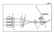
実施の形態4.
図9は本発明の実施の形態4に係るレーザ装置の構成を示す図である。実施の形態4に係るレーザ装置100−4は、実施の形態3に係るレーザ装置100−3の構成に加えて、複数のレーザビームの重畳面を分散素子3上にリレーするリレー光学系7を備える。リレー光学系7は波長フィルタ4と分散素子3との間に配置される。レーザ装置100−4によれば、実施の形態3における波長フィルタの特性と分散素子3の特性との関係を調整できるため、低コストの標準品を使用して設計の自由度が拡大するため、レーザ装置の製造コストを低減できる。Embodiment 4 FIG.
FIG. 9 is a diagram showing a configuration of a laser apparatus according to Embodiment 4 of the present invention. In addition to the configuration of the laser device 100-3 according to the third embodiment, the laser device 100-4 according to the fourth embodiment includes a relay
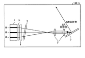
実施の形態5.
図10は本発明の実施の形態5に係るレーザ装置の構成を示す図である。実施の形態5に係るレーザ装置100−5ではコリメータ5が傾けられており、傾けられたコリメータ5を用いることにより重畳レンズ2が省かれている。レーザ装置100−5によれば、重畳レンズ2を省くことができるためレーザ装置の製造コストを低減できる。
FIG. 10 is a diagram showing a configuration of a laser apparatus according to
実施の形態6.
図11は本発明の実施の形態6に係るレーザ装置の構成を示す図である。実施の形態6に係るレーザ装置では、2つのレーザユニット1が用いられており、複数のレーザユニット1からのレーザビームが分散素子3に重畳される。実施の形態6に係るレーザ装置では、複数のレーザ媒質が分散素子3面の法線を挟んで正及び負の角度で分散素子3に入射する位置に配置される。この構成により、より多数のレーザ媒質の光を重畳でき、パワー及び輝度を向上できるという効果を得ることができる。
FIG. 11 is a diagram showing a configuration of a laser apparatus according to
なお実施の形態1〜5に係るレーザ装置には、第2のレーザビームが分散素子3の+1次回折光もしくは−1次回折光である場合、分散素子3で発生する0次回折光を回収する光学系を追加しても良い。この構成によれば、損失となっていた0次回折光を回収し、エネルギー効率の向上を図ることができる。分散素子3における0次回折光は不可避的に発生し、一般的には損失となる。0次回折光の回収と利用については、一例として米国特許出願公開第2015/0333485号明細書に開示されているが、0次回折光及びその派生ビームが高反射面の間に閉じ込められて容易に出力に結合することができないため、効果的な動作が困難である。本実施の形態では、0次回折光、1次回折光及び2次回折光を発生する3ポートを備えた分散素子3が用いられ、分散素子3が一種のサーキュレータとして動作し、出力に結合された0次回折光を回収することができる。以上のように0次回折光を回収する光学系は、1次回折光及び2次回折光を同時に発生する分散素子3を用いる構成において格別の効果を奏するものである。
In the laser devices according to the first to fifth embodiments, when the second laser beam is the + 1st order diffracted light or the −1st order diffracted light of the
以上の実施の形態に示した構成は、本発明の内容の一例を示すものであり、別の公知の技術と組み合わせることも可能であるし、本発明の要旨を逸脱しない範囲で、構成の一部を省略、変更することも可能である。 The configuration described in the above embodiment shows an example of the contents of the present invention, and can be combined with another known technique, and can be combined with other configurations without departing from the gist of the present invention. It is also possible to omit or change the part.
1 レーザユニット、2 重畳レンズ、3,31,32 分散素子、4 波長フィルタ、5 コリメータ、6 ビーム回転素子、7 リレー光学系、11 レーザ媒質、40 部分反射鏡、50,51 共振器、60 波長フィルタ、70 共振器部、80 ビーム結合部、100−1,100−2,100−3,100−4,100−5,100A,100B レーザ装置。 1 laser unit, 2 superimposing lens, 3, 31, 32 dispersion element, 4 wavelength filter, 5 collimator, 6 beam rotating element, 7 relay optical system, 11 laser medium, 40 partial reflecting mirror, 50, 51 resonator, 60 wavelength Filter, 70 resonator unit, 80 beam coupling unit, 100-1, 100-2, 100-3, 100-4, 100-5, 100A, 100B Laser device.
Claims (10)
前記分散素子は、前記重畳手段により複数の前記レーザビームが1つに重畳された位置に設置されると共に、互いに波長の異なるレーザビームの2次回折光をそれぞれの前記レーザ媒質へ帰還させ、互いに波長の異なるレーザビームの+1次回折光及び−1次回折光を1つの光軸を有するレーザビームとして出力することを特徴とするレーザ装置。 A laser device that combines a plurality of laser media that generate laser beams having different wavelengths and a laser beam emitted from each of the plurality of laser media by superimposing them on a dispersive element in a superposed manner. ,
The dispersive element is installed at a position where a plurality of the laser beams are superimposed on each other by the superimposing means, and returns the second-order diffracted light beams of laser beams having different wavelengths to the respective laser media so that the wavelength is mutually A laser apparatus that outputs + 1st order diffracted light and −1st order diffracted light of laser beams having different optical beams as laser beams having one optical axis .
前記リトロー配置は、前記+1次回折光及び前記−1次回折光を出射し、前記2次回折光をそれぞれの前記レーザ媒質へ帰還させる配置であることを特徴とする請求項1に記載のレーザ装置。 The dispersive element may be re Torrox arranged,
2. The laser device according to claim 1, wherein the Littrow arrangement is an arrangement for emitting the + 1st order diffracted light and the −1st order diffracted light and returning the second order diffracted light to the laser medium .
Applications Claiming Priority (1)
| Application Number | Priority Date | Filing Date | Title |
|---|---|---|---|
| PCT/JP2017/001924 WO2018134966A1 (en) | 2017-01-20 | 2017-01-20 | Laser device |
Publications (2)
| Publication Number | Publication Date |
|---|---|
| JP6211237B1 true JP6211237B1 (en) | 2017-10-11 |
| JPWO2018134966A1 JPWO2018134966A1 (en) | 2019-01-31 |
Family
ID=60040463
Family Applications (1)
| Application Number | Title | Priority Date | Filing Date |
|---|---|---|---|
| JP2017533509A Active JP6211237B1 (en) | 2017-01-20 | 2017-01-20 | Laser equipment |
Country Status (4)
| Country | Link |
|---|---|
| US (1) | US10498107B1 (en) |
| JP (1) | JP6211237B1 (en) |
| CN (1) | CN110337763B (en) |
| WO (1) | WO2018134966A1 (en) |
Cited By (1)
| Publication number | Priority date | Publication date | Assignee | Title |
|---|---|---|---|---|
| JP6696629B1 (en) * | 2018-10-22 | 2020-05-20 | 三菱電機株式会社 | Laser equipment |
Families Citing this family (3)
| Publication number | Priority date | Publication date | Assignee | Title |
|---|---|---|---|---|
| EP4235986A4 (en) * | 2020-10-26 | 2024-09-11 | Fujikura Ltd. | Laser module and fiber laser device |
| CN112909725B (en) * | 2021-01-13 | 2022-05-20 | 华中科技大学 | Star-reflection-based blue light semiconductor laser wavelength beam combining device and method |
| US20230221440A1 (en) * | 2022-01-10 | 2023-07-13 | Beijing Voyager Technology Co., Ltd. | Synchronized beam scanning and wavelength tuning |
Citations (3)
| Publication number | Priority date | Publication date | Assignee | Title |
|---|---|---|---|---|
| JP2015513792A (en) * | 2012-02-14 | 2015-05-14 | テラダイオード,インコーポレーテッド | Two-dimensional multi-beam stabilizer and combining system and method |
| WO2015083200A1 (en) * | 2013-12-05 | 2015-06-11 | 三菱電機株式会社 | Multi-wavelength laser device |
| JP2016096333A (en) * | 2014-11-10 | 2016-05-26 | 三菱電機株式会社 | Semiconductor laser device |
Family Cites Families (7)
| Publication number | Priority date | Publication date | Assignee | Title |
|---|---|---|---|---|
| US7949030B2 (en) * | 2005-02-03 | 2011-05-24 | Pd-Ld, Inc. | High-power, phased-locked, laser arrays |
| WO2011109763A2 (en) | 2010-03-05 | 2011-09-09 | TeraDiode, Inc. | Selective repositioning and rotation wavelength beam combining system and method |
| CN103081261B (en) * | 2010-03-05 | 2016-03-09 | 泰拉二极管公司 | Wavelength beam combining system and method |
| JP2013062484A (en) * | 2011-08-24 | 2013-04-04 | Gigaphoton Inc | Laser device |
| JP2013145819A (en) * | 2012-01-16 | 2013-07-25 | Shimadzu Corp | Semiconductor laser device |
| US9306369B2 (en) * | 2013-11-22 | 2016-04-05 | Trumpf Laser Gmbh | Wavelength selective external resonator and beam combining system for dense wavelength beam combining laser |
| CN105811245A (en) * | 2016-05-18 | 2016-07-27 | 上海高意激光技术有限公司 | Laser array beam combining device |
-
2017
- 2017-01-20 JP JP2017533509A patent/JP6211237B1/en active Active
- 2017-01-20 CN CN201780077849.0A patent/CN110337763B/en not_active Expired - Fee Related
- 2017-01-20 WO PCT/JP2017/001924 patent/WO2018134966A1/en not_active Ceased
- 2017-01-20 US US16/344,821 patent/US10498107B1/en active Active
Patent Citations (3)
| Publication number | Priority date | Publication date | Assignee | Title |
|---|---|---|---|---|
| JP2015513792A (en) * | 2012-02-14 | 2015-05-14 | テラダイオード,インコーポレーテッド | Two-dimensional multi-beam stabilizer and combining system and method |
| WO2015083200A1 (en) * | 2013-12-05 | 2015-06-11 | 三菱電機株式会社 | Multi-wavelength laser device |
| JP2016096333A (en) * | 2014-11-10 | 2016-05-26 | 三菱電機株式会社 | Semiconductor laser device |
Cited By (1)
| Publication number | Priority date | Publication date | Assignee | Title |
|---|---|---|---|---|
| JP6696629B1 (en) * | 2018-10-22 | 2020-05-20 | 三菱電機株式会社 | Laser equipment |
Also Published As
| Publication number | Publication date |
|---|---|
| JPWO2018134966A1 (en) | 2019-01-31 |
| CN110337763A (en) | 2019-10-15 |
| US20190348817A1 (en) | 2019-11-14 |
| WO2018134966A1 (en) | 2018-07-26 |
| CN110337763B (en) | 2020-08-14 |
| US10498107B1 (en) | 2019-12-03 |
Similar Documents
| Publication | Publication Date | Title |
|---|---|---|
| US9306369B2 (en) | Wavelength selective external resonator and beam combining system for dense wavelength beam combining laser | |
| JP6211237B1 (en) | Laser equipment | |
| JP6818867B2 (en) | Wavelength coupled laser device | |
| WO2017197883A1 (en) | Laser array beam combining device | |
| US7065107B2 (en) | Spectral beam combination of broad-stripe laser diodes | |
| JPWO2017022142A1 (en) | Semiconductor laser device | |
| JP4947367B2 (en) | External resonator type tunable light source | |
| US6700904B2 (en) | Light source for an external cavity laser | |
| CN104300368A (en) | Semiconductor laser beam combination device | |
| CN108429129A (en) | The conjunction beam system and method for multi-thread array semiconductor laser grating external-cavity spectrum | |
| CN112928597A (en) | Semiconductor laser optical fiber coupling module | |
| CN118137292A (en) | Semiconductor lasers and laser devices | |
| CN107404061B (en) | A semiconductor laser external cavity coherent beam combining system | |
| US20020090017A1 (en) | Device and method for reduction of spontaneous emission from external cavity lasers | |
| JP2009283531A (en) | Wavelength-variable light source | |
| JP6223650B1 (en) | Laser oscillator | |
| JP4402030B2 (en) | External cavity semiconductor laser | |
| WO2009020813A1 (en) | Linewidth-narrowed excimer laser cavity | |
| CN214100229U (en) | Narrow linewidth external cavity semiconductor laser linear array based on diffraction grating array | |
| CN107453206B (en) | A semiconductor laser spectral beam combining system | |
| JP2004511914A (en) | Tunable single mode laser device | |
| JP2011018779A (en) | Wavelength variable light source | |
| CN108551078A (en) | A kind of semiconductor laser beam merging apparatus | |
| WO2023021675A1 (en) | Semiconductor laser device and illumination device | |
| CN112600068A (en) | Narrow linewidth external cavity semiconductor laser linear array based on diffraction grating array |
Legal Events
| Date | Code | Title | Description |
|---|---|---|---|
| A521 | Request for written amendment filed |
Free format text: JAPANESE INTERMEDIATE CODE: A523 Effective date: 20170620 |
|
| A621 | Written request for application examination |
Free format text: JAPANESE INTERMEDIATE CODE: A621 Effective date: 20170620 |
|
| A871 | Explanation of circumstances concerning accelerated examination |
Free format text: JAPANESE INTERMEDIATE CODE: A871 Effective date: 20170620 |
|
| A975 | Report on accelerated examination |
Free format text: JAPANESE INTERMEDIATE CODE: A971005 Effective date: 20170712 |
|
| TRDD | Decision of grant or rejection written | ||
| A01 | Written decision to grant a patent or to grant a registration (utility model) |
Free format text: JAPANESE INTERMEDIATE CODE: A01 Effective date: 20170815 |
|
| A61 | First payment of annual fees (during grant procedure) |
Free format text: JAPANESE INTERMEDIATE CODE: A61 Effective date: 20170912 |
|
| R150 | Certificate of patent or registration of utility model |
Ref document number: 6211237 Country of ref document: JP Free format text: JAPANESE INTERMEDIATE CODE: R150 |
|
| R250 | Receipt of annual fees |
Free format text: JAPANESE INTERMEDIATE CODE: R250 |
|
| R250 | Receipt of annual fees |
Free format text: JAPANESE INTERMEDIATE CODE: R250 |
|
| R250 | Receipt of annual fees |
Free format text: JAPANESE INTERMEDIATE CODE: R250 |
|
| R250 | Receipt of annual fees |
Free format text: JAPANESE INTERMEDIATE CODE: R250 |
|
| R250 | Receipt of annual fees |
Free format text: JAPANESE INTERMEDIATE CODE: R250 |
|
| R250 | Receipt of annual fees |
Free format text: JAPANESE INTERMEDIATE CODE: R250 |