JP6232768B2 - 照光スイッチ - Google Patents
照光スイッチ Download PDFInfo
- Publication number
- JP6232768B2 JP6232768B2 JP2013127952A JP2013127952A JP6232768B2 JP 6232768 B2 JP6232768 B2 JP 6232768B2 JP 2013127952 A JP2013127952 A JP 2013127952A JP 2013127952 A JP2013127952 A JP 2013127952A JP 6232768 B2 JP6232768 B2 JP 6232768B2
- Authority
- JP
- Japan
- Prior art keywords
- light
- optical pattern
- light source
- deflection plate
- illumination switch
- Prior art date
- Legal status (The legal status is an assumption and is not a legal conclusion. Google has not performed a legal analysis and makes no representation as to the accuracy of the status listed.)
- Expired - Fee Related
Links
Images






Landscapes
- Push-Button Switches (AREA)
- Switch Cases, Indication, And Locking (AREA)
- Non-Portable Lighting Devices Or Systems Thereof (AREA)
- Planar Illumination Modules (AREA)
Description
r=Lz×tanθ
I(θ)=k×sinθ×cosnθ/〔tan2(θ+Δθ)−tan2(θ−Δθ)〕=0.8
ただし、Lzは光源と光偏向プレートとの距離
Δθ=0.1
kはI(0.0001)=1によって決まる値
nは前記光源の指向性を表すパラメータ
で決まる半径rの範囲内に光学パターンを設けていることを特徴としている。少なくともこの半径rの範囲内の光学パターンを最適化しておけば、照光スイッチの輝度分布を均一化することができる。
22 光源
24 光偏向プレート
25 カラープレート
26 押ボタン
30 光学パターン
32、33 光透過部
34 反射シート
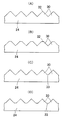
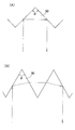
以下、図3−図9を参照して本発明の実施形態1による照光スイッチの構造を説明する。図3は本発明の実施形態1による照光スイッチ21の全体斜視図である。図4は、照光スイッチ21の分解斜視図である。図5は、照光スイッチ21の断面図である。また、図6−図9は、種々の光偏向プレート24の構造を示す概略断面図である。
X方向における光偏向プレート24の幅: 25mm
光学パターン30の頂角: 90°
光学パターン30の配列ピッチPch: 0.24mm
光透過部32の曲率半径: 0.03mm
上記のような構造の照光スイッチ21によれば、照光スイッチ21における輝度分布の均一性を高くすることができる。以下、その理由(光学的作用)を説明する。なお、光偏向プレート24及び光学パターン30は、上記のように種々の形状のものを用いることが可能であるが、以下においては、図6(A)及び図6(B)に示した光偏向プレート24を用いた場合について説明する。
I(θ)=k×sinθ×cosnθ/〔tan2(θ+Δθ)−tan2(θ−Δθ)〕
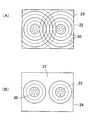
ここで、nは光源22の指向性を表すパラメータであって、例えばランバート光ではn=1となる。Δθは微小な角度変化で、0.1°程度であればよい。kは任意の定数であるが、I(0.0001)=1となるように決められる。I(0.0001)=1となるように規格化したとき、光偏向プレート24の上面には、少なくともI(θ)≧0.8を満たす円形領域内に、先に示した頂角と有効斜面率を持つ光学パターン30を設ければよい。したがって、最低限光学パターン30を設けなければならない円形領域35の半径rは、次の2式より定まる。
I(θ)=0.8
r=Lz×tanθ
Claims (7)
- 押ボタンと、
前記押ボタンの操作により接点間を開閉する接点開閉機構部と、
前記押ボタンの操作により点灯または消灯する複数個の光源と、
を備えた照光スイッチにおいて、
前記光源に対向させて光偏向プレートを設け、
前記光偏向プレートの前記光源と反対側の面の、少なくとも前記光源の主軸付近に共通な一方向に延びた複数条の光学パターンと光透過部とを設けてあり、
前記光学パターンは、頂角が67°以上105°以下となる一対の傾斜面を有する断面三角プリズム状に形成され、
前記光透過部は、前記光学パターンの稜線または谷線部分に沿って設けられた、平坦面または緩やかな曲面または前記傾斜面よりも緩やかな傾斜角の傾斜面のいずれかによって形成され、
複数個の前記光源は、前記光学パターンの延びている方向と直交する方向に沿った間隔が、前記光学パターンの延びている方向に沿った間隔よりも大きくなるように配置されていることを特徴とする照光スイッチ。 - 4個の前記光源が矩形状に配置されていることを特徴とする、請求項1に記載の照光スイッチ。
- 前記光偏向プレートの表面において、少なくとも前記光源の主軸から次式:
r=Lz×tanθ
I(θ)=k×sinθ×cosnθ/〔tan2(θ+Δθ)−tan2(θ−Δθ)〕=0.8
ただし、Lzは光源と光偏向プレートとの距離
Δθ=0.1
kはI(0.0001)=1によって決まる値
nは前記光源の指向性を表すパラメータ
で決まる半径rの範囲内に光学パターンを設けていることを特徴とする、請求項1に記載の照光スイッチ。 - 前記光源の主軸付近における前記光学パターンの頂角が、73°以上82°以下もしくは88°以上100°以下であることを特徴とする、請求項1に記載の照光スイッチ。
- 前記光偏向プレートは、透明又は半透明の乳白色材料によって形成されていることを特徴とする、請求項1に記載の照光スイッチ。
- 前記光偏向プレートに、微細な光拡散材を分散させていることを特徴とする、請求項1に記載の照光スイッチ。
- 前記光偏向プレートの、前記光学パターンを形成された面に対して反対側の面に、光を拡散させるための凹凸を形成したことを特徴とする、請求項1に記載の照光スイッチ。
Priority Applications (3)
| Application Number | Priority Date | Filing Date | Title |
|---|---|---|---|
| JP2013127952A JP6232768B2 (ja) | 2013-06-18 | 2013-06-18 | 照光スイッチ |
| CN201420274328.8U CN203895304U (zh) | 2013-06-18 | 2014-05-27 | 照光开关 |
| CN201410227748.5A CN104240997B (zh) | 2013-06-18 | 2014-05-27 | 照光开关 |
Applications Claiming Priority (1)
| Application Number | Priority Date | Filing Date | Title |
|---|---|---|---|
| JP2013127952A JP6232768B2 (ja) | 2013-06-18 | 2013-06-18 | 照光スイッチ |
Publications (2)
| Publication Number | Publication Date |
|---|---|
| JP2015002165A JP2015002165A (ja) | 2015-01-05 |
| JP6232768B2 true JP6232768B2 (ja) | 2017-11-22 |
Family
ID=51721674
Family Applications (1)
| Application Number | Title | Priority Date | Filing Date |
|---|---|---|---|
| JP2013127952A Expired - Fee Related JP6232768B2 (ja) | 2013-06-18 | 2013-06-18 | 照光スイッチ |
Country Status (2)
| Country | Link |
|---|---|
| JP (1) | JP6232768B2 (ja) |
| CN (2) | CN104240997B (ja) |
Families Citing this family (3)
| Publication number | Priority date | Publication date | Assignee | Title |
|---|---|---|---|---|
| JP6232768B2 (ja) * | 2013-06-18 | 2017-11-22 | オムロン株式会社 | 照光スイッチ |
| JP6413852B2 (ja) * | 2015-03-10 | 2018-10-31 | オムロン株式会社 | 押しボタンスイッチ |
| JP7653842B2 (ja) * | 2021-06-09 | 2025-03-31 | 株式会社デンソーテン | 操作装置 |
Family Cites Families (8)
| Publication number | Priority date | Publication date | Assignee | Title |
|---|---|---|---|---|
| JPH078805U (ja) * | 1993-06-29 | 1995-02-07 | 第二しなのポリマー株式会社 | 指向性拡散体とその応用 |
| FR2812966B1 (fr) * | 2000-08-11 | 2002-12-20 | Telecomm Electronique Aeronaut | Touche lumineuse multi-messages a eclairages independants, notamment pour facade d'equipement aeronautique, et barrette constituee de telles touches |
| JP2006134715A (ja) * | 2004-11-05 | 2006-05-25 | Fujikura Ltd | スイッチ構造 |
| JP4826414B2 (ja) * | 2006-09-28 | 2011-11-30 | オムロン株式会社 | 押し釦スイッチ |
| US7455416B2 (en) * | 2006-11-17 | 2008-11-25 | Ichia Technologies, Inc. | Light guide structure and keypad having the same |
| CN201262908Y (zh) * | 2008-07-29 | 2009-06-24 | 达方电子股份有限公司 | 键帽以及具有该键帽的按键结构及键盘 |
| JP5274537B2 (ja) * | 2010-11-19 | 2013-08-28 | オムロン株式会社 | 照光式押しボタンスイッチおよび操作パネル |
| JP6232768B2 (ja) * | 2013-06-18 | 2017-11-22 | オムロン株式会社 | 照光スイッチ |
-
2013
- 2013-06-18 JP JP2013127952A patent/JP6232768B2/ja not_active Expired - Fee Related
-
2014
- 2014-05-27 CN CN201410227748.5A patent/CN104240997B/zh active Active
- 2014-05-27 CN CN201420274328.8U patent/CN203895304U/zh not_active Expired - Lifetime
Also Published As
| Publication number | Publication date |
|---|---|
| CN203895304U (zh) | 2014-10-22 |
| JP2015002165A (ja) | 2015-01-05 |
| CN104240997A (zh) | 2014-12-24 |
| CN104240997B (zh) | 2017-08-25 |
Similar Documents
| Publication | Publication Date | Title |
|---|---|---|
| US7582913B2 (en) | Lens and LED using the lens to achieve homogeneous illumination | |
| KR101264323B1 (ko) | 점광원을 이용한 면발광 백라이트 유닛 및 면발광 램프 | |
| JP5510038B2 (ja) | コリメート光源及び面光源装置 | |
| JP6369353B2 (ja) | 導光体および発光装置 | |
| JP2005135844A (ja) | 光学素子及びバックライト装置 | |
| JP2010238659A (ja) | 面発光装置及び液晶表示装置 | |
| JP6406053B2 (ja) | 導光体および発光装置 | |
| US20190024855A1 (en) | Luminous flux control member, light-emitting device, planar light source device, and display device | |
| JPH0868997A (ja) | 液晶表示装置 | |
| JP6232768B2 (ja) | 照光スイッチ | |
| JP7024399B2 (ja) | 光源ユニットおよび照明器具 | |
| JP6016190B2 (ja) | 光偏向素子並びに当該素子を用いた照光スイッチ及び面光源装置 | |
| JP2018142418A (ja) | 発光装置、面光源装置および表示装置 | |
| JP6390194B2 (ja) | 光学素子及び面光源装置 | |
| TW202001380A (zh) | 面狀照明裝置 | |
| CN203881967U (zh) | 偏光板、面光源装置及照光开关 | |
| JP6751452B2 (ja) | 面状照明装置 | |
| KR101535906B1 (ko) | 백라이트 장치 | |
| JP2012145829A (ja) | 発光装置および照明装置 | |
| JP7504590B2 (ja) | 面光源装置および表示装置 | |
| JP7482705B2 (ja) | 照明装置 | |
| CN111373194B (zh) | 照明装置 | |
| JP4725434B2 (ja) | スイッチ用プリズム | |
| KR20110060473A (ko) | 조명 장치 및 광학 플레이트 | |
| JP2022111718A (ja) | 光束制御部材、発光装置、面光源装置および表示装置 |
Legal Events
| Date | Code | Title | Description |
|---|---|---|---|
| A621 | Written request for application examination |
Free format text: JAPANESE INTERMEDIATE CODE: A621 Effective date: 20160509 |
|
| A977 | Report on retrieval |
Free format text: JAPANESE INTERMEDIATE CODE: A971007 Effective date: 20170228 |
|
| A131 | Notification of reasons for refusal |
Free format text: JAPANESE INTERMEDIATE CODE: A131 Effective date: 20170307 |
|
| A521 | Request for written amendment filed |
Free format text: JAPANESE INTERMEDIATE CODE: A523 Effective date: 20170427 |
|
| TRDD | Decision of grant or rejection written | ||
| A01 | Written decision to grant a patent or to grant a registration (utility model) |
Free format text: JAPANESE INTERMEDIATE CODE: A01 Effective date: 20170926 |
|
| A61 | First payment of annual fees (during grant procedure) |
Free format text: JAPANESE INTERMEDIATE CODE: A61 Effective date: 20171009 |
|
| R150 | Certificate of patent or registration of utility model |
Ref document number: 6232768 Country of ref document: JP Free format text: JAPANESE INTERMEDIATE CODE: R150 |
|
| LAPS | Cancellation because of no payment of annual fees |