JP6233023B2 - Acoustic processing apparatus, acoustic processing method, and acoustic processing program - Google Patents
Acoustic processing apparatus, acoustic processing method, and acoustic processing program Download PDFInfo
- Publication number
- JP6233023B2 JP6233023B2 JP2014000178A JP2014000178A JP6233023B2 JP 6233023 B2 JP6233023 B2 JP 6233023B2 JP 2014000178 A JP2014000178 A JP 2014000178A JP 2014000178 A JP2014000178 A JP 2014000178A JP 6233023 B2 JP6233023 B2 JP 6233023B2
- Authority
- JP
- Japan
- Prior art keywords
- impulse response
- sound
- head
- delay time
- measurement
- Prior art date
- Legal status (The legal status is an assumption and is not a legal conclusion. Google has not performed a legal analysis and makes no representation as to the accuracy of the status listed.)
- Expired - Fee Related
Links
Images




Landscapes
- Stereophonic System (AREA)
Description
本発明は、音響処理装置、音響処理方法および音響処理プログラムに関する。 The present invention relates to an acoustic processing device, an acoustic processing method, and an acoustic processing program.
音が人の頭部や耳介の影響を受けて左右の耳に入るまでの時間的な特性を示す頭部インパルス応答(HRIR: Head Related Impulse Response)を用いることで、任意の方向から音が聞こえてくるように人に感じさせる技術がある。この種の技術は、音像定位技術あるいは立体音響技術と呼ばれている。 By using the head related impulse response (HRIR), which shows the temporal characteristics of the sound from the human head and pinna to the left and right ears, the sound can be heard from any direction. There is technology that makes people feel as if they are heard. This kind of technology is called sound image localization technology or stereophonic technology.
頭部インパルス応答には個人差がある。そこで、個人の頭部の周囲に設けられた複数の音源のそれぞれを用いて頭部インパルス応答を計測し、計測した複数の頭部インパルス応答を互いに補間することで、任意の方向の頭部インパルス応答を求める技術が提案されている(例えば、特許文献1参照)。また、複数の方向について計測した個人の頭部インパルス応答相互の補間に、複数の人物について計測して蓄積した頭部インパルス応答に対する統計的な学習で求めた共通の頭部インパルス応答を用いる手法が提案されている(例えば、特許文献2,3参照)。 There are individual differences in the head impulse response. Therefore, a head impulse response in an arbitrary direction is obtained by measuring a head impulse response using each of a plurality of sound sources provided around an individual's head and interpolating the measured plurality of head impulse responses with each other. A technique for obtaining a response has been proposed (see, for example, Patent Document 1). In addition, there is a method that uses a common head impulse response obtained by statistical learning for head impulse responses measured and accumulated for a plurality of persons for interpolation between individual head impulse responses measured for a plurality of directions. It has been proposed (see, for example, Patent Documents 2 and 3).
複数の方向について計測した個人の頭部インパルス応答を補間することで任意の方向の頭部インパルス応答を生成する従来の技術では、個人の頭部の周囲に例えば等間隔で複数の音源を配置した状態で、個人の頭部インパルス応答の計測が行われる。したがって、この種の技術では、個人の頭部インパルス応答を計測するために、大規模な計測装置が設けられる場合が多く、また、周囲に設けられた音源のそれぞれについて計測が繰り返されるので、頭部インパルス応答の計測作業も煩雑である。 In the conventional technology for generating a head impulse response in an arbitrary direction by interpolating individual head impulse responses measured in a plurality of directions, for example, a plurality of sound sources are arranged at equal intervals around the individual head. In the state, an individual's head impulse response is measured. Therefore, in this type of technology, in order to measure an individual's head impulse response, a large-scale measuring device is often provided, and the measurement is repeated for each of the sound sources provided around the head. The measurement work of the part impulse response is also complicated.
ところで、例えば、展示会などに集まった多数の人物のそれぞれを対象として音像定位技術を用いたサービスを実現するためには、多数の人物のそれぞれに対応して、任意の方向についての頭部インパルス応答を用意することが望ましい。 By the way, for example, in order to realize a service using sound image localization technology for a large number of persons gathered at an exhibition, etc., a head impulse in an arbitrary direction corresponding to each of the large number of persons. It is desirable to have a response.
しかしながら、多数の人物のそれぞれに対応した頭部インパルス応答の計測に大規模な計測装置を準備し、また、煩雑な作業を繰り返すことは、計測装置を設置する場所の制約や時間的な制約のために、実現が困難である。 However, preparing a large-scale measuring device for measuring the head impulse response corresponding to each of a large number of people and repeating complicated operations may cause restrictions on the place where the measuring device is installed and time constraints. Therefore, realization is difficult.
本件開示の音響処理装置、音響処理方法および音響処理プログラムは、一部の方向について個人毎に計測した頭部インパルス応答を用いて、良好な音像定位を実現する技術を提供することを目的とする。 The acoustic processing device, the acoustic processing method, and the acoustic processing program of the present disclosure are intended to provide a technique for realizing a good sound image localization using a head impulse response measured for each individual in a part of a direction. .
一つの観点によれば、音響処理装置は、頭部の前方方向の所定の範囲内の複数の第1方向のそれぞれから頭部に音響が到達する際に計測されたインパルス応答に基づいて、所定の範囲の外側の第2方向から頭部に音響が到達する際のインパルス応答の遅延時間を予測する予測部と、第2方向からの音響に対して予めモデル化された基準のインパルス応答の遅延時間を、予測部で予測された遅延時間に合わせて補正する補正部と、を備え、予測部は、頭部とインパルス応答の計測の際に第1方向に設置された音源との位置関係として、音源から到達する音響の遅延時間が、計測されたインパルス応答の遅延時間となる位置関係を特定する特定部と、特定部によって特定された位置関係に基づいて、第2方向から頭部に音響が到達する場合に予測される遅延時間を算出する算出部と、を有する。 According to one aspect, the sound processing device performs predetermined processing based on an impulse response measured when sound reaches the head from each of a plurality of first directions within a predetermined range in the forward direction of the head. A prediction unit for predicting a delay time of an impulse response when the sound reaches the head from the second direction outside the range, and a reference impulse response delay modeled in advance for the sound from the second direction A correction unit that corrects the time according to the delay time predicted by the prediction unit , and the prediction unit is a positional relationship between the head and the sound source installed in the first direction when measuring the impulse response. Based on the positional relationship specified by the specifying unit that specifies the positional relationship in which the delay time of the sound that arrives from the sound source becomes the delay time of the measured impulse response, the sound from the second direction to the head Predict if will reach Having a calculation unit for calculating a delay time.
別の観点によれば、音響処理方法は、頭部の前方方向の所定の範囲内の複数の第1方向のそれぞれから頭部に音響が到達する際に計測されたインパルス応答に基づいて、所定の範囲の外側の第2方向から頭部に音響が到達する際のインパルス応答の遅延時間を予測する予測工程と、第2方向からの音響に対して予めモデル化された基準のインパルス応答の遅延時間を、予測工程で予測された遅延時間に合わせて補正する補正工程と、を含み、予測工程は、頭部とインパルス応答の計測の際に第1方向に設置された音源との位置関係として、音源から到達する音響の遅延時間が、計測されたインパルス応答の遅延時間となる位置関係を特定する特定工程と、特定工程によって特定された位置関係に基づいて、第2方向から頭部に音響が到達する場合に予測される遅延時間を算出する算出工程と、を有する。 According to another aspect, the sound processing method is based on an impulse response measured when sound reaches the head from each of a plurality of first directions within a predetermined range in the forward direction of the head. A prediction step for predicting a delay time of the impulse response when the sound reaches the head from the second direction outside the range, and a delay of the reference impulse response modeled in advance for the sound from the second direction A correction step that corrects the time according to the delay time predicted in the prediction step , and the prediction step is a positional relationship between the head and the sound source installed in the first direction when measuring the impulse response. Based on the positional relationship that specifies the positional relationship in which the delay time of the sound that arrives from the sound source becomes the measured delay time of the impulse response, and the positional relationship that is identified by the identifying step, the sound from the second direction to the head Reach It has a calculation step of calculating a delay time which is predicted if the.
別の観点によれば、音響処理プログラムは、頭部の前方方向の所定の範囲内の複数の第1方向のそれぞれから頭部に音響が到達する際に計測されたインパルス応答に基づいて、所定の範囲の外側の第2方向から頭部に音響が到達する際のインパルス応答の遅延時間を予測する予測工程と、第2方向からの音響に対して予めモデル化された基準のインパルス応答の遅延時間を、予測工程で予測された遅延時間に合わせて補正する補正工程と、を含む処理をコンピュータに実行させ、予測工程は、頭部とインパルス応答の計測の際に第1方向に設置された音源との位置関係として、音源から到達する音響の遅延時間が、計測されたインパルス応答の遅延時間となる位置関係を特定する特定工程と、特定工程によって特定された位置関係に基づいて、第2方向から頭部に音響が到達する場合に予測される遅延時間を算出する算出工程と、を有する。 According to another aspect, the sound processing program is based on an impulse response measured when sound reaches the head from each of a plurality of first directions within a predetermined range in the forward direction of the head. A prediction step for predicting a delay time of the impulse response when the sound reaches the head from the second direction outside the range, and a delay of the reference impulse response modeled in advance for the sound from the second direction And a correction step for correcting the time according to the delay time predicted in the prediction step. The computer executes a process including a correction step, and the prediction step is installed in the first direction when measuring the head and the impulse response. As a positional relationship with the sound source, based on the positional relationship identified by the identifying step and the identifying step that identifies the positional relationship in which the delay time of the sound that arrives from the sound source becomes the measured delay time of the impulse response Having a calculation step of calculating a delay time which is expected if the acoustic reaches the head from the second direction.
本発明の音響処理装置、音響処理方法および音響処理プログラムは、一部の方向について個人毎に計測した頭部インパルス応答を用いて、良好な音像定位を実現することができる。 The sound processing apparatus, sound processing method, and sound processing program of the present invention can realize a good sound image localization by using a head impulse response measured for each individual in some directions.
以下、図面に基づいて、実施形態を説明する。以下では、所定の計測範囲に含まれる方向ついて個人毎に計測された頭部インパルス応答と、計測範囲に含まれない他の方向について予め用意した共通の頭部インパルス応答とを組み合わせて利用する技術が説明される。 Hereinafter, embodiments will be described with reference to the drawings. In the following, a technique of using a combination of a head impulse response measured for each individual in a direction included in a predetermined measurement range and a common head impulse response prepared in advance for other directions not included in the measurement range Is explained.
ここで、人物の頭部の向きを基準とする角度で示される様々な方向についての頭部インパルス応答を比較すると、人物の頭部の前方の頭部インパルス応答は、頭部の側方及び後方の頭部インパルス応答に比べて個人差が大きい。そこで、以下では、人物の頭部の向きを含む所定の範囲について個人毎に計測した頭部インパルス応答と、個人毎の計測を行わない範囲についてダミーヘッドを用いた計測などにより予めモデル化された頭部インパルス応答とを組み合わせる場合について説明する。 Here, when comparing the head impulse response in various directions indicated by an angle with respect to the orientation of the person's head, the head impulse response in front of the person's head is The individual difference is larger than the head impulse response. Therefore, in the following, the head impulse response measured for each individual for a predetermined range including the orientation of the person's head and the range not measured for each individual are modeled in advance by measurement using a dummy head, etc. A case of combining with the head impulse response will be described.
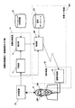
図1は、音響処理装置の一実施形態を示す。図1に示した音響処理装置10は、予測部11と、補正部12とを含んでいる。また、図1に示した計測装置EQは、図2を用いて説明する所定の計測範囲Rの内側に設定された複数の方向である第1方向について、人物Q1に固有の頭部インパルス応答を計測し、計測で得られた人物Q1の頭部インパルス応答を音響処理装置10に渡す。また、図1に示した記憶装置SDは、計測装置EQによる計測範囲Rの外側に設定された複数の方向である第2方向について、ダミーヘッドなどを用いた計測を行うことで得られた別の頭部インパルス応答を示す情報を格納している。記憶装置SDは、音響処理装置10とは独立した構成要素として設けられてもよいし、音響処理装置10に含まれていてもよい。
FIG. 1 shows an embodiment of a sound processing apparatus. The
以下の説明において、計測装置EQによる計測で得られる人物Q1に固有の頭部インパルス応答は、個別頭部インパルス応答と称される。また、記憶装置SDに格納された情報で示される別の頭部インパルス応答は、共通頭部インパルス応答と称される。共通頭部インパルス応答は、ダミーヘッドなどを用いた計測によって得られた頭部インパルス応答に限られず、計測範囲Rの外側に設定された第2方向からの音響に対して予めモデル化された頭部インパルス応答であればよい。例えば、共通頭部インパルス応答は、多数の人物についての計測で得られた頭部インパルス応答の学習によりモデル化された頭部インパルス応答でもよい。なお、計測装置EQによる個別頭部インパルス応答の計測および共通頭部インパルス応答の計測については、図2を用いて後述する。 In the following description, the head impulse response unique to the person Q1 obtained by measurement by the measuring device EQ is referred to as an individual head impulse response. Further, another head impulse response indicated by information stored in the storage device SD is referred to as a common head impulse response. The common head impulse response is not limited to the head impulse response obtained by measurement using a dummy head or the like, but is a head modeled in advance with respect to the sound from the second direction set outside the measurement range R. Any partial impulse response may be used. For example, the common head impulse response may be a head impulse response modeled by learning a head impulse response obtained by measurement for a large number of persons. The measurement of the individual head impulse response and the measurement of the common head impulse response by the measurement device EQ will be described later with reference to FIG.
図1に示した音響処理装置10において、予測部11は、計測装置EQによって第1方向のそれぞれについて計測された個別頭部インパルス応答を受ける。予測部11は、受けた個別頭部インパルス応答に基づいて、図3及び図4を用いて後述する予測処理を行い、計測装置EQによる計測範囲Rの外側に設定された複数の第2方向のそれぞれから人物Q1に音響が到達する場合の遅延時間を予測する。予測部11において、各第2方向について予測された遅延時間は、補正部12に渡される。補正部12は、図5を用いて後述する補正処理を行うことで、記憶装置SDに各第2方向に対応して格納された共通頭部インパルス応答の遅延時間を、同じ方向について予測された遅延時間に合わせる。補正部12によって遅延時間が補正された共通頭部インパルス応答と計測された個別頭部インパルス応答とは、次に述べる音響AR(Augmented Reality:拡張現実)装置ARCに渡される。音響AR装置ARCに渡された個別頭部インパルス応答と補正された共通頭部インパルス応答とは、任意の方向に音像を定位させる処理である音像定位処理において、組み合わせて用いられる。
In the
音響AR装置ARCは、制御部CNTと、音声データベースDB1と、例えば、スマートホンやタブレット型端末などの人物Q1によって携帯可能な端末装置UEに内蔵された音響処理部SPとを含んでいる。制御部CNTは、音声データベースDB1に接続されており、制御部CNTは、音声データベースDB1に格納された音声情報を取得可能である。また、制御部CNTと音響処理部SPとは、例えば、無線LAN(Local Area Network)などを用いた通信経路により接続されている。音響処理部SPは、制御部CNTから受けた音声情報に基づいて音響信号を生成する機能を有する。 The acoustic AR device ARC includes a control unit CNT, an audio database DB1, and an acoustic processing unit SP built in the terminal device UE that can be carried by a person Q1, such as a smart phone or a tablet terminal. The control unit CNT is connected to the voice database DB1, and the control unit CNT can acquire the voice information stored in the voice database DB1. The control unit CNT and the acoustic processing unit SP are connected by a communication path using, for example, a wireless LAN (Local Area Network). The acoustic processing unit SP has a function of generating an acoustic signal based on audio information received from the control unit CNT.
制御部CNTは、例えば、音像定位処理により音像が定位させられる方向毎に、音響処理装置10から渡される個別頭部インパルス応答あるいは補正された共通頭部インパルス応答を対応付ける。例えば、制御部CNTは、所定の計測範囲Rの内側に設定された第1方向のそれぞれと、当該第1方向についての計測で得られた個別頭部インパルス応答との対応関係を示す情報を内部のメモリなどに記憶する。また、制御部CNTは、計測範囲Rの外側に設定された第2方向のそれぞれと、当該第2方向に対応する共通頭部インパルス応答の遅延時間を補正することで得られた補正後の共通頭部インパルス応答との対応関係を示す情報を内部のメモリなどに記憶する。
For example, the control unit CNT associates the individual head impulse response or the corrected common head impulse response passed from the
制御部CNTは、音声データベースDB1から取得した音声情報を音響処理部SPに渡す際に、音像を定位させる方向に対応して格納された個別頭部インパルス応答あるいは補正された共通頭部インパルス応答を示す情報を内部のメモリなどから読み出す。そして、制御部CNTは、内部のメモリなどから読み出した情報を、音声情報から生成した音響信号に適用する頭部インパルス応答を示す情報として、音声データベースDB1から取得した音声情報とともに音響処理部SPに渡す。 When the control unit CNT passes the sound information acquired from the sound database DB1 to the sound processing unit SP, the control unit CNT outputs the individual head impulse response stored corresponding to the direction in which the sound image is localized or the corrected common head impulse response. The indicated information is read from an internal memory or the like. Then, the control unit CNT uses the information read from the internal memory or the like as information indicating a head impulse response to be applied to the acoustic signal generated from the speech information, together with the speech information acquired from the speech database DB1, to the acoustic processing unit SP. hand over.
音響処理部SPは、制御部CNTから受けた音声情報に基づいて音響信号を生成する。また、音響処理部SPは、内蔵のフィルタを用いて、制御部CNTから渡される頭部インパルス応答と音声情報から生成した音響信号との畳み込み処理を行い、畳み込み処理後の音響信号を、人物Q1の耳に装着されたイアホンEPL,EPRにより出力する。 The acoustic processing unit SP generates an acoustic signal based on the audio information received from the control unit CNT. In addition, the acoustic processing unit SP performs a convolution process between the head impulse response passed from the control unit CNT and the acoustic signal generated from the voice information using a built-in filter, and the acoustic signal after the convolution processing is converted into the person Q1. Is output by the earphones EPL and EPR attached to the ears.
すなわち、図1に示した音響AR装置ARCは、人物Q1に対して第1方向のそれぞれに音像を定位させる音響の生成に、人物Q1に同じ第1方向から音響を到達させた状態で計測された個別頭部インパルス応答を用いる。そして、音響AR装置ARCは、人物Q1に対して第2方向に音像を定位させる音響の生成に、第2方向からの音響に対してモデル化された共通頭部インパルス応答の遅延時間を補正することで得られた補正後の共通頭部インパルス応答を用いる。 That is, the acoustic AR device ARC shown in FIG. 1 is measured in a state in which sound is caused to reach the person Q1 from the same first direction to generate sound that localizes the sound image in the first direction with respect to the person Q1. Individual head impulse responses are used. Then, the acoustic AR device ARC corrects the delay time of the common head impulse response modeled with respect to the sound from the second direction to generate sound that localizes the sound image in the second direction with respect to the person Q1. The corrected common head impulse response obtained by the above is used.
なお、端末装置UEは、スマートホンやタブレット型端末に限らず、人物Q1による持ち運びが可能であり、イアホンEPL,EPRにステレオ音響を出力させるための音響処理部SPを含む装置であればよく、携帯電話や携帯型ゲーム機などでもよい。また、音響AR装置ARCの制御部CNTは、端末装置UEに含まれていてもよいし、また、音響処理装置10は、音響AR装置ARCの制御部CNT及び音響処理部SPを含んでもよい。
The terminal device UE is not limited to a smart phone or a tablet-type terminal, and can be carried by a person Q1, and may be any device including an acoustic processing unit SP for causing the earphones EPL and EPR to output stereo sound. A mobile phone or a portable game machine may be used. Further, the control unit CNT of the acoustic AR device ARC may be included in the terminal device UE, and the
次に、音響処理装置10に含まれる予測部11および補正部12の機能および動作の説明に先立って、計測装置EQにより、個別頭部インパルス応答を計測する手法について説明する。
Next, prior to description of the functions and operations of the
図2は、図1に示した計測装置EQにより個別頭部インパルス応答を計測する範囲の例を示す。なお、図2に示す要素のうち、図1に示した要素と同等のものは、同一の符号で示すとともに要素の説明を省略する場合がある。 FIG. 2 shows an example of a range in which the individual head impulse response is measured by the measuring apparatus EQ shown in FIG. 2 that are equivalent to the elements shown in FIG. 1 are denoted by the same reference numerals and description of the elements may be omitted.
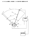
図2に示した人物Q1の耳EL,ERのそれぞれには、マイクロホンMCL,MCRが装着されている。マイクロホンMCL,MCRの出力は、計測装置EQに接続されている。計測装置EQは、インパルス応答の測定用の信号であるTSP(Time stretched Pulse)信号を生成する機能を有しており、生成したTSP信号をスピーカS1に入力する。なお、図2の例では、スピーカS1は、人物Q1の頭部の正面の方向を示す向きDirを基準にして角度θ1の方向に人物Q1から距離Dの位置に設置されている。また、図2において、点線で示した円形S’は、図2とともに図4を用いて後述する共通頭部インパルス応答の計測に用いられる音源の一例を示す。 Microphones MCL and MCR are attached to the ears EL and ER of the person Q1 shown in FIG. The outputs of the microphones MCL and MCR are connected to the measuring device EQ. The measuring device EQ has a function of generating a TSP (Time stretched Pulse) signal that is a signal for measuring an impulse response, and inputs the generated TSP signal to the speaker S1. In the example of FIG. 2, the speaker S <b> 1 is installed at a distance D from the person Q <b> 1 in the direction of the angle θ <b> 1 with reference to the direction Dir indicating the front direction of the head of the person Q <b> 1. In FIG. 2, a circle S ′ indicated by a dotted line indicates an example of a sound source used for measurement of a common head impulse response, which will be described later with reference to FIG. 4 together with FIG. 2.
計測装置EQは、例えば、スピーカS1から人物Q1に到達した音響を、マイクロホンMCL,MCRで得られる音響信号として受ける。そして、受けた音響信号で示されるインパルス応答を、人物Q1の頭部の向きDirから角度θ1で示される方向について個別頭部インパルス応答として音響処理装置10に渡す。即ち、計測装置EQは、個別頭部インパルス応答を計測する。
The measuring device EQ receives, for example, sound that has reached the person Q1 from the speaker S1 as sound signals obtained by the microphones MCL and MCR. Then, the impulse response indicated by the received acoustic signal is passed to the
同様にして、計測装置EQは、人物Q1の頭部の向きDirを中心軸とし、中心角2φの扇形で示される計測範囲Rにおいて、スピーカS1が設置される角度θ1を変えながら、個別頭部インパルス応答の計測を行う。例えば、計測装置EQは、計測範囲Rを示す扇形の弧上に計測を行う角度θ1のそれぞれで示される位置に設置された複数のスピーカS1のそれぞれに順次にTSP信号に対応する音響を発生させる。そして、計測装置EQは、各スピーカS1の位置に対応する第1方向(例えば、角度θ1の方向)から人物Q1に到達した音響を示す音響信号から、第1方向のそれぞれについての個別頭部インパルス応答を求める。なお、図2に示した計測範囲Rは、人物Q1の正面の向きDirを基準とする角度が所定の範囲内である計測範囲の一例であり、角度θ1で示される方向は、計測範囲Rの内側に設定された複数の第1方向の一例である。また、計測範囲Rを示す扇形の中心角2φは、例えば、角度180度よりも小さい角度であり、120度〜150度程度に設定されることが望ましい。 Similarly, the measuring apparatus EQ changes the individual head while changing the angle θ1 at which the speaker S1 is installed in the measurement range R indicated by a fan shape having a central angle 2φ with the head direction Dir of the person Q1 as the central axis. Measure impulse response. For example, the measuring device EQ sequentially generates sound corresponding to the TSP signal in each of the plurality of speakers S1 installed at the positions indicated by the angles θ1 at which the measurement is performed on the fan-shaped arc indicating the measurement range R. . Then, the measuring device EQ uses the individual head impulse for each of the first directions from the acoustic signal indicating the sound that has reached the person Q1 from the first direction (for example, the direction of the angle θ1) corresponding to the position of each speaker S1. Ask for a response. The measurement range R shown in FIG. 2 is an example of a measurement range in which an angle with respect to the front direction Dir of the person Q1 is within a predetermined range, and the direction indicated by the angle θ1 is the direction of the measurement range R. It is an example of the several 1st direction set inside. Further, the sector-shaped central angle 2φ indicating the measurement range R is, for example, an angle smaller than an angle of 180 degrees, and is preferably set to about 120 to 150 degrees.
図2に示した計測範囲Rに含まれる各方向についての個別頭部インパルス応答の計測は、人物Q1の周囲の360度方向について頭部インパルス応答を計測する場合に比べて少ないスペースで計測を行うことができる。このため、人物Q1の周囲の360度方向について頭部インパルス応答を計測する場合に比べて、スピーカS1の設置数及びスピーカS1と計測装置EQとを接続する配線数を削減することができ、また、計測時間も短縮できる。 The measurement of the individual head impulse response for each direction included in the measurement range R shown in FIG. 2 is performed in a smaller space than when the head impulse response is measured for the 360-degree direction around the person Q1. be able to. For this reason, compared with the case where the head impulse response is measured in the 360-degree direction around the person Q1, the number of speakers S1 and the number of wires connecting the speakers S1 and the measuring device EQ can be reduced. Measurement time can be shortened.
次に、人物Q1の頭部を基準とする所定の範囲について計測された個別頭部インパルス応答の遅延時間を用いて、共通頭部インパルス応答の遅延時間を補正する手法について説明する。 Next, a method for correcting the delay time of the common head impulse response using the delay time of the individual head impulse response measured for a predetermined range based on the head of the person Q1 will be described.
図1に示した予測部11は、計測装置EQから受けた個別頭部インパルス応答に基づいて、図2に示した計測範囲Rの外側に設定された複数の第2方向のそれぞれから音響が到達する際のインパルス応答の遅延時間を予測する。
The
予測部11は、各第1方向の個別頭部インパルス応答に基づいて、第1方向のそれぞれから音響が人物Q1の頭部に到達する際の遅延時間を特定する。例えば、予測部11は、計測装置EQから受けた個別頭部インパルス応答において、音響が発生した時刻から波形の振幅が所定の閾値以上となるまでの時間を遅延時間とする。なお、遅延時間の特定に用いる閾値は、例えば、音響信号において、雑音成分を判別する際に用いられる閾値と同等の値を設定することが望ましい。
The
図3は、個別頭部インパルス応答の例を示す。なお、図3に示した座標軸tは、音響が生成された時刻からの時間を示し、座標軸Pは音圧を示す。ここで、音響が生成された時刻としては、図2に示した計測装置EQからスピーカS1にTSP信号が渡された時刻を用いることが望ましい。 FIG. 3 shows an example of an individual head impulse response. The coordinate axis t shown in FIG. 3 indicates the time from the time when the sound is generated, and the coordinate axis P indicates the sound pressure. Here, as the time when the sound is generated, it is desirable to use the time when the TSP signal is passed from the measuring apparatus EQ shown in FIG. 2 to the speaker S1.
図3の例は、図2において角度θ1で示した方向から人物Q1の頭部に音響を到達させた際にマイクロホンMCL,MCRのいずれかで得られた音響信号から求めた個別頭部インパルス応答の波形を示す。図3の例において、図2において角度θ1で示される方向についての個別頭部インパルス応答の遅延時間は、座標軸tの原点(t=0)から個別頭部インパルス応答を示す波形が閾値Thpを初めて超えるまでの時間δp(θ1)で示される。なお、図3の例では、人物Q1の耳の一方について求められた個別頭部インパルス応答を示し、他方の耳について求められた個別頭部インパルス応答の図示は省略されている。 The example of FIG. 3 shows an individual head impulse response obtained from an acoustic signal obtained by either the microphone MCL or MCR when the sound reaches the head of the person Q1 from the direction indicated by the angle θ1 in FIG. The waveform is shown. In the example of FIG. 3, the delay time of the individual head impulse response in the direction indicated by the angle θ1 in FIG. 2 is the first time that the waveform showing the individual head impulse response from the origin (t = 0) of the coordinate axis t has the threshold value Thp. It is indicated by the time δp (θ1) until it exceeds. In the example of FIG. 3, the individual head impulse response obtained for one ear of the person Q1 is shown, and the individual head impulse response obtained for the other ear is not shown.
予測部11は、図2に示した計測範囲Rの内側に設定された各第1方向(例えば、図2のθ1)と、個別頭部インパルス応答の遅延時間δp(θ1)との関係から、計測範囲Rの外側の他の方向からの音響に対するインパルス応答の遅延時間を予測する。
From the relationship between each first direction (for example, θ1 in FIG. 2) set inside the measurement range R shown in FIG. 2 and the delay time δp (θ1) of the individual head impulse response, the
図4は、遅延時間と音源の方向との関係の例を示す。図4において、座標軸θは、図2に示した人物Q1の頭部の向きDirを基準とする音源の方向を示し、座標軸tは、図3に示した遅延時間を示す。なお、図4の例において、図2に示した人物Q1の頭部の正面の向きDirから時計回りで測った角度は、座標軸θにおいて正の値として示され、人物Q1の頭部の向きDirから反時計回りに測った角度は、座標軸θにおいて負の値として示される。すなわち、図2に示した計測範囲Rは、図4に示した座標軸θにおいて、角度「−φ」〜角度「+φ」の範囲に相当する。 FIG. 4 shows an example of the relationship between the delay time and the direction of the sound source. 4, the coordinate axis θ represents the direction of the sound source with reference to the head direction Dir of the person Q1 shown in FIG. 2, and the coordinate axis t represents the delay time shown in FIG. In the example of FIG. 4, the angle measured clockwise from the front direction Dir of the head of the person Q1 shown in FIG. 2 is shown as a positive value on the coordinate axis θ, and the head direction Dir of the person Q1. The angle measured counterclockwise from is indicated as a negative value on the coordinate axis θ. That is, the measurement range R shown in FIG. 2 corresponds to a range from the angle “−φ” to the angle “+ φ” on the coordinate axis θ shown in FIG.
また、図4の例において、黒丸のそれぞれは、図2に示した計測範囲Rに設定された複数の第1方向のそれぞれに配置された音源から音響が人物Q1の一方の耳に到達する場合について計測された個別頭部インパルス応答が示す遅延時間を示す。例えば、黒色の円形Pm(θ1)は、図2に示した人物Q1の頭部の向きDirに対して角度θ1の方向に音源(例えば、スピーカS1)がある場合について計測された個別頭部インパルス応答に現れる遅延時間を示す。なお、図4においては、人物Q1の他方の耳に音響が到達する場合について計測された個別頭部インパルス応答が示す遅延時間と音源の方向との関係についての図示は省略されている。 In the example of FIG. 4, each of the black circles represents a case where sound reaches one ear of the person Q1 from a sound source arranged in each of the plurality of first directions set in the measurement range R shown in FIG. The delay time which the individual head impulse response measured about is shown. For example, the black circle Pm (θ1) is the individual head impulse measured when the sound source (for example, the speaker S1) is in the direction of the angle θ1 with respect to the head direction Dir of the person Q1 shown in FIG. Indicates the delay time that appears in the response. In FIG. 4, the illustration of the relationship between the delay time indicated by the individual head impulse response measured when the sound reaches the other ear of the person Q1 and the direction of the sound source is omitted.
図1に示した予測部11は、例えば、図4に示した複数の黒丸の分布に近似する曲線CVを求めることで、音源の方向と遅延時間との関係を推定する。そして、予測部11は、推定した関係を示す曲線CVに基づいて、図2に示した計測範囲Rの外側に設定された第2方向のそれぞれに音源を配置した計測を行った場合に想定される個別頭部インパルス応答が示す遅延時間を予測する。なお、予測部11において、計測された個別頭部インパルス応答で示される遅延時間から計測範囲Rの外側に設定される各方向から音響が到達する場合に予測される遅延時間を求める方法は、図4に示した曲線CVを求める方法に限られない。例えば、予測部11は、図7から図9を用いて後述する手法を用いて、音源の方向と遅延時間との関係を推定してもよい。
The
図1に示した記憶装置SDには、図2に示した計測範囲Rの外側に設定された第2方向のそれぞれについて、ダミーヘッドなどを用いて予め計測された共通頭部インパルス応答を示す情報が記憶されている。なお、共通頭部インパルス応答は、ダミーヘッドを用いて計測された頭部インパルス応答に限られない。例えば、共通頭部インパルス応答は、図2に示した人物Q1とは別の人物の頭部に図2に示した計測範囲Rの外側に設定された第2方向のそれぞれから音響を到達させた状態で計測した頭部インパルス応答でもよい。また、図2において、点線で示した円形S’は、共通頭部インパルス応答の計測に用いた音源の一例を示す。 In the storage device SD shown in FIG. 1, information indicating the common head impulse response measured in advance using a dummy head or the like for each of the second directions set outside the measurement range R shown in FIG. Is remembered. The common head impulse response is not limited to the head impulse response measured using a dummy head. For example, the common head impulse response causes sound to reach the head of a person different from the person Q1 shown in FIG. 2 from each of the second directions set outside the measurement range R shown in FIG. It may be a head impulse response measured in a state. In FIG. 2, a circle S ′ indicated by a dotted line indicates an example of a sound source used for measurement of the common head impulse response.
ここで、図2に示した人物Q1の頭部と個別頭部インパルス応答の計測に用いられた音源であるスピーカS1との距離Dと、ダミーヘッドと共通頭部インパルス応答の計測に用いられた音源S’との距離D’とは、厳密には一致しない場合がある。なぜなら、人物Q1の両耳を結ぶ線分の中点およびダミーヘッドの両耳を結ぶ線分の中点のそれぞれを、計測範囲Rを示す扇形の中心に位置決めすることは困難だからである。同様に、人物Q1の両耳間の距離と、共通頭部インパルス応答の計測のためにダミーヘッドに装着された2つのマイクロホン相互の距離とは、厳密には一致しない場合がある。このため、図2に示した計測範囲Rの外側に設定された第2方向のそれぞれについて予測された遅延時間と、対応する方向に音源がある場合について記憶装置SDに記憶された共通頭部インパルス応答が示す遅延時間とは一致しない場合がある。例えば、人物Q1の頭部の向きDirから角度θ2(θ2<−φ)の方向について図4に示した曲線CVから予測される遅延時間τ(θ2)と、同じ角度θ2で示される方向に音源S’がある場合の共通頭部インパルス応答が示す遅延時間とは、必ずしも一致しない。 Here, the distance D between the head of the person Q1 shown in FIG. 2 and the speaker S1, which is the sound source used for the measurement of the individual head impulse response, and the dummy head and the common head impulse response were measured. The distance D ′ to the sound source S ′ may not exactly match. This is because it is difficult to position the midpoint of the line connecting both ears of the person Q1 and the midpoint of the line connecting both ears of the dummy head at the center of the sector indicating the measurement range R. Similarly, the distance between both ears of the person Q1 and the distance between the two microphones attached to the dummy head for the measurement of the common head impulse response may not exactly match. Therefore, the delay time predicted for each of the second directions set outside the measurement range R shown in FIG. 2 and the common head impulse stored in the storage device SD when there is a sound source in the corresponding direction. The delay time indicated by the response may not match. For example, the sound source in the direction indicated by the same angle θ2 as the delay time τ (θ2) predicted from the curve CV shown in FIG. 4 in the direction of the angle θ2 (θ2 <−φ) from the head direction Dir of the person Q1. It does not necessarily match the delay time indicated by the common head impulse response when S ′ is present.
そこで、図1に示した補正部12は、図2に示した計測範囲Rの外側に設定された複数の第2方向のそれぞれについて記憶装置SDに記憶された共通頭部インパルス応答に、予測部11によって対応する方向について求められた遅延時間を示させる補正を行う。
Therefore, the
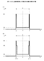
図5は、共通頭部インパルス応答の遅延時間の補正例を示す。図5において、座標軸tは、共通頭部インパルス応答における時間の経過を示し、座標軸Pは、音圧を示す。 FIG. 5 shows an example of correcting the delay time of the common head impulse response. In FIG. 5, the coordinate axis t represents the passage of time in the common head impulse response, and the coordinate axis P represents the sound pressure.
図5(A)は、図2に示した人物Q1の頭部の位置に、ダミーヘッドの正面の向きを人物Q1の頭部の向きDirと一致させて配置し、頭部の向きDirと角度θ2で交差する方向から音響を到達させた状態で計測された頭部インパルス応答の例である。即ち、図5(A)に示した頭部インパルス応答は、図1に示した記憶装置SDに角度θ2に対応して記憶された共通頭部インパルス応答の一例である。なお、角度θ2で示される方向は、図2に示した計測範囲Rの外側に設定された第2方向の一つである。図5(A)に示した共通頭部インパルス応答の遅延時間は、共通頭部インパルス応答を表す波形が閾値Thpを初めて超える時刻δc(θ2)で示される。 FIG. 5A shows the position of the head of the person Q1 shown in FIG. 2 with the front direction of the dummy head aligned with the direction Dir of the head of the person Q1, and the angle with the head direction Dir. It is an example of a head impulse response measured in a state where sound is made to reach from a direction intersecting at θ2. That is, the head impulse response shown in FIG. 5A is an example of the common head impulse response stored in correspondence with the angle θ2 in the storage device SD shown in FIG. Note that the direction indicated by the angle θ2 is one of the second directions set outside the measurement range R shown in FIG. The delay time of the common head impulse response shown in FIG. 5A is indicated by a time δc (θ2) when the waveform representing the common head impulse response first exceeds the threshold Thp.
また、図5(B)は、図1に示した補正部12で得られる補正された共通頭部インパルス応答の例を示す。すなわち、補正部12は、図5(A)に示した共通頭部インパルス応答の遅延時間を補正することで、図5(B)に示す補正後の共通頭部インパルス応答を得る。
FIG. 5B shows an example of the corrected common head impulse response obtained by the
図1に示した補正部12は、記憶装置SDに第2方向のそれぞれについて保持されている共通頭部インパルス応答を時間軸方向において移動させることで、第2方向のそれぞれについて予測部11によって予測された遅延時間に合わせる。
The
例えば、補正部12は、図2に示した頭部の向きDirから角度θ2の方向について、図4に示した関係から予測された遅延時間τ(θ2)と図5(A)に示した共通頭部インパルス応答の遅延時間δc(θ2)との差分dτを求める。そして、補正部12は、差分dτがなくなるように、角度θ2で示される方向の共通頭部インパルス応答を座標軸t上で移動させる。補正部12は、以上に説明した補正を行うことで、移動後の共通頭部インパルス応答の波形が閾値Thpを超えるまでの経過時間と、予測部11によって予測された遅延時間とをほぼ同等にする。
For example, the
図6は、図1に示した音響処理装置10の動作を示す。図6に示したステップS301〜ステップS303の処理は、図1に示した音響処理装置10の動作を示す。また、図6に示した各ステップの処理は、個人について計測された個別頭部インパルス応答と予め用意された共通頭部インパルス応答とを用いて任意の方向についての音像定位を実現するための音響処理方法および音響処理プログラムの例を示す。例えば、図6に示す処理は、音響処理装置10に搭載されたプロセッサが音響処理プログラムを実行することで実現される。なお、図6に示す処理は、音響処理装置10に搭載されるハードウェアによって実行されてもよい。
FIG. 6 shows the operation of the
ステップS301において、図1に示した音響処理装置10は、例えば、図2に示した計測範囲Rの内側に設定された複数の第1方向のそれぞれについて、計測装置EQによって計測された個別頭部インパルス応答を受ける。
In step S301, the
ステップS302において、図1に示した予測部11は、計測された個別頭部インパルス応答から、図2に示した計測範囲Rの外側に設定された複数の第2方向について計測した場合に得られる個別頭部インパルス応答が示す遅延時間を予測する。
In step S302, the
ステップS303において、図1に示した補正部12は、第2方向のそれぞれに対応する共通頭部インパルス応答が示す遅延時間を、ステップS302の処理で予測された遅延時間に近づける補正を行う。
In step S303, the
以上に説明したステップS303の処理で遅延時間が補正された共通頭部インパルス応答は、ステップS301の処理で計測装置EQから受けた個別頭部インパルス応答とともに、図1に示した音響AR装置ARCに渡される。 The common head impulse response whose delay time has been corrected in the process of step S303 described above is applied to the acoustic AR device ARC shown in FIG. 1 together with the individual head impulse response received from the measurement apparatus EQ in the process of step S301. Passed.
そして、音響AR装置ARCは、図2に示した計測範囲Rの内側に設定された第1方向に音像を定位させる音響の生成に、同じ方向からの音響に対して計測された個別頭部インパルス応答を用いる。また、音響AR装置ARCは、計測範囲Rの外側に設定された第2方向に音像を定位させる音響の生成に、同じ方向からの音響に対してモデル化された共通頭部インパルス応答の遅延時間を補正することで得られた補正後の共通頭部インパルス応答を用いる。 The acoustic AR device ARC then generates individual head impulses measured with respect to the sound from the same direction to generate sound that localizes the sound image in the first direction set inside the measurement range R shown in FIG. Use a response. The acoustic AR device ARC also generates a delay time of the common head impulse response modeled for the sound from the same direction in generating the sound that localizes the sound image in the second direction set outside the measurement range R. The corrected common head impulse response obtained by correcting is used.
つまり、図1に示した音響AR装置ARCにおいて、第2方向に音像を定位させる音響の生成に用いられる頭部インパルス応答の遅延時間は、同じ第2方向について予測部11によって予測された遅延時間とほぼ同等になる。ここで、予測部11によって予測された遅延時間は、図2に示したスピーカS1が配置された弧の延長上に設置された別のスピーカS1’から人物Q1に音響を到達させた状態で計測される頭部インパルス応答の遅延時間とほぼ同等である。
That is, in the acoustic AR device ARC shown in FIG. 1, the delay time of the head impulse response used for generating the sound that localizes the sound image in the second direction is the delay time predicted by the
即ち、図1に示した音響処理装置10は、任意の方向に音像を定位させるために音響AR装置ARCによって生成される音響において、対応する方向についての個別頭部インパルス応答が示す遅延時間を再現することができる。したがって、図1に示した音響処理装置10を用いることにより、人物Q1に聴取させる音響が有する遅延時間の観点において、全ての方向につき個別頭部インパルス応答を計測した場合と同等の良好な音像定位を実現することができる。
That is, the
ここで、人間は、両耳のそれぞれで聴取した音響の時間差に基づいて、聴取した音響に対応する音源の方向を知覚する。したがって、任意の方向に音像を定位させる音響において、対応する方向についての個別頭部インパルス応答が示す遅延時間を再現することで、人物Q1と音源との相対位置が変化する場合にも、人物Q1に不自然な印象を与えない音響を聴取させることができる。 Here, the human perceives the direction of the sound source corresponding to the heard sound based on the time difference of the sound heard by both ears. Therefore, in the sound that localizes the sound image in an arbitrary direction, even when the relative position between the person Q1 and the sound source changes by reproducing the delay time indicated by the individual head impulse response in the corresponding direction, the person Q1 The sound that does not give an unnatural impression can be heard.
また、図2を用いて説明したように、計測範囲Rに含まれる各方向について個別頭部インパルス応答を計測するために用いるスペースは、人物Q1の周囲360度についての計測のために用いられるスペースよりも小さい。更に、計測範囲Rを分割して得られる複数の範囲ごとに個別頭部インパルス応答を計測することで、個別頭部インパルス応答の計測のために用意するスペースを縮小することも可能である。例えば、計測範囲Rを示す扇形の内角をn(nは2以上の整数)個に分割して得られる図形に外接する程度の大きさの矩形を底面とする箱型のブース内に、回転可能なイスと複数のスピーカとを対向させて配置することで、個別頭部インパルス応答の計測は可能である。この場合に、図2に計測範囲Rに含まれる各方向の個別頭部インパルス応答は、イスに着席した人物Q1と複数のスピーカとの相対位置を変えて、計測処理をn回繰り返すことで計測することができる。 In addition, as described with reference to FIG. 2, the space used for measuring the individual head impulse response in each direction included in the measurement range R is a space used for measurement about 360 degrees around the person Q1. Smaller than. Furthermore, by measuring the individual head impulse response for each of a plurality of ranges obtained by dividing the measurement range R, it is possible to reduce the space prepared for measuring the individual head impulse response. For example, it can be rotated in a box-shaped booth with a rectangular bottom that is circumscribed by a figure that is obtained by dividing the inner angle of the sector shape indicating the measurement range R into n (n is an integer of 2 or more). An individual head impulse response can be measured by arranging a chair and a plurality of speakers facing each other. In this case, the individual head impulse response in each direction included in the measurement range R in FIG. 2 is measured by changing the relative position between the person Q1 seated on the chair and the plurality of speakers and repeating the measurement process n times. can do.
以上に説明したように、図1に示した音響処理装置10で用いる個別頭部インパルス応答の計測は、従来の技術で用いられたような大規模な設備を用いなくても実現することが可能である。したがって、例えば、展示会などの会場の一角などに、個別頭部インパルス応答の計測用のブースを設け、展示会などに集まった多数の人物のそれぞれについて、個別頭部インパルス応答の計測を行うことが可能である。そして、多数の人物のそれぞれについての計測で得られた個別頭部インパルス応答を用いて、各人物に対して音像定位技術を用いたサービスを提供することが可能となる。なお、図1に示した音響処理装置10を用いて、例えば、人物Q1に対して音像定位技術を用いたサービスを提供する音響ARシステムについては、図12〜図17を用いて後述する。
As described above, the measurement of the individual head impulse response used in the
次に、図1に示した予測部11において、計測に用いられたマイクロホンと音源との位置関係を推定することで、人物Q1の頭部の向きDirを基準とする音源の方向と、個別頭部インパルス応答が示す遅延時間との関係を推定する手法について説明する。
Next, the
図7は、図2に示したマイクロホンMCL,MCRとスピーカS1との位置関係の例を示す。なお、図7に示す要素のうち、図2に示した要素と同等のものは、同一の符号で示すとともに要素の説明を省略する場合がある。また、図7に示したスピーカS1は、個別頭部インパルス応答の計測に用いられた音源の一例である。 FIG. 7 shows an example of the positional relationship between the microphones MCL and MCR and the speaker S1 shown in FIG. Of the elements shown in FIG. 7, elements equivalent to those shown in FIG. 2 are denoted by the same reference numerals and description of the elements may be omitted. Moreover, the speaker S1 shown in FIG. 7 is an example of a sound source used for measurement of an individual head impulse response.
図7において、線分DLおよび線分DRは、スピーカS1と2つのマイクロホンMCL,MCRとを互いに結んで得られる三角形の辺のうち、スピーカS1に相当する頂点を挟む2つの辺をそれぞれ示す。即ち、図7に示した線分DLの長さ|DL|は、スピーカS1からマイクロホンMCLまでの距離を示し、線分DRの長さ|DR|は、スピーカS1からマイクロホンMCRまでの距離を示す。また、線分Dは、2つのマイクロホンMCL,MCRを互いに結ぶ線分の中点QcとスピーカS1とを結んで得られる線分を示す。そして、線分Dの長さYは、2つのマイクロホンMCL,MCRを互いに結ぶ線分Wの中点QcからスピーカS1までの距離を示し、線分Wの長さXは、2つのマイクロホンMCL,MCR間の距離を示す。すなわち、線分Dの長さYは、人物Q1の両耳を結ぶ線分の中点からスピーカS1までの距離を示し、線分Wの長さXは、人物Q1の両耳の間の距離を示す。 In FIG. 7, a line segment DL and a line segment DR indicate two sides sandwiching the apex corresponding to the speaker S1 among the triangular sides obtained by connecting the speaker S1 and the two microphones MCL and MCR to each other. That is, the length | DL | of the line segment DL shown in FIG. 7 indicates the distance from the speaker S1 to the microphone MCL, and the length | DR | of the line segment DR indicates the distance from the speaker S1 to the microphone MCR. . A line segment D indicates a line segment obtained by connecting the midpoint Qc of the line segment connecting the two microphones MCL and MCR and the speaker S1. The length Y of the line segment D indicates the distance from the midpoint Qc of the line segment W connecting the two microphones MCL and MCR to the speaker S1, and the length X of the line segment W indicates the two microphones MCL, The distance between MCR is shown. That is, the length Y of the line segment D indicates the distance from the midpoint of the line segment connecting both ears of the person Q1 to the speaker S1, and the length X of the line segment W indicates the distance between both ears of the person Q1. Indicates.
スピーカS1が人物Q1の頭部の正面の向きDirを基準として角度θの方向にある場合に、スピーカS1からマイクロホンMCL、MCRまでの距離|DL|および距離|DR|のそれぞれは、角度θの関数として式(1)、式(2)で表される。なお、式(1)、式(2)において、符号Yは、線分Wの中点QcからスピーカS1までの距離を示し、符号Xは、2つのマイクロホンMCL,MCR間の距離Xを示す。 When the speaker S1 is in the direction of the angle θ with respect to the front direction Dir of the head of the person Q1, the distance | DL | and the distance | DR | from the speaker S1 to the microphones MCL and MCR are It is represented by the formula (1) and the formula (2) as functions. In equations (1) and (2), the symbol Y indicates the distance from the midpoint Qc of the line segment W to the speaker S1, and the symbol X indicates the distance X between the two microphones MCL and MCR.

図8は、音響処理装置10の別実施形態を示す。なお、図8に示す構成要素のうち、図1に示した構成要素と同等のものは、同一の符号で示すとともに構成要素の説明を省略する場合がある。
FIG. 8 shows another embodiment of the
図8に示した音響処理装置10は、予測部11および補正部12に加えて、記憶装置SDと生成部13とを含んでいる。図8の例では、計測装置EQによる第1方向のそれぞれについての計測で得られた個別頭部インパルス応答(個別HRIR:Head Related Impulse Response)PIRは、例えば、第1方向のそれぞれに対応して記憶装置SDに格納される。また、記憶装置SDは、第2方向のそれぞれに対応して予め用意された共通頭部インパルス応答(共通HRIR)CIRを格納しており、補正部12は、記憶装置SDにアクセスすることで、共通頭部インパルス応答CIRを取得する。そして、補正部12によって補正された共通頭部インパルス応答(補正HRIR)AIRは、記憶装置SDに格納される。
The
図8に示した生成部13は、例えば、設定部131と、選択部132と、音響処理部SPと、記憶部MEMとを含んでいる。図8に示した音響処理部SPは、例えば、端末装置UEに搭載されたハードウェアである。また、記憶部MEMは、端末装置UEに内蔵されたメモリの一部を用いて実現される。そして、選択部132は、例えば、端末装置UEに搭載されたプロセッサにより、図17を用いて後述するアプリケーションプログラムを実行することによって実現される。また、設定部131は、例えば、無線LANなどのネットワークNWを介して端末装置UEに接続されており、記憶部MEMに対するアクセスが可能である。
The
図8に示した生成部13において、設定部131は、図2に示した計測範囲Rの内側に設定された第1方向のそれぞれに対応して、当該第1方向についての計測で得られた個別頭部インパルス応答を記憶部MEMに記憶させる。また、設定部131は、計測範囲Rの外側に設定された第2方向のそれぞれに対応して、当該第2方向についての共通頭部インパルス応答の遅延時間を補正することで得られた補正後の共通頭部インパルス応答を記憶部MEMに記憶させる。
In the
選択部132は、例えば、ネットワークNWを介して、サーバ装置SVから音像を定位させる方向を示す情報を受け、受けた情報で示される方向に対応して記憶部MEMに格納された個別頭部インパルス応答あるいは補正後の共通頭部インパルス応答を読み出す。そして、選択部132は、読み出した個別頭部インパルス応答あるいは補正後の共通頭部インパルス応答を、サーバ装置SVからの情報で示された方向に音像を定位させる音響の生成に用いるインパルス応答として音響処理部SPに渡す。
For example, the
また、音声データベースDB1に蓄積された音響情報は、例えば、サーバ装置SVによって読み出され、ネットワークNWを介して、音響処理部SPに渡される。そして、音響処理部SPは、サーバ装置SVから渡された音響情報から生成した音響信号と選択部132から渡されたインパルス応答との畳み込み処理を行うことで、サーバ装置SVからの情報で示された方向に音像を定位させる音響を生成する。
In addition, the acoustic information stored in the voice database DB1 is read by, for example, the server device SV, and passed to the acoustic processing unit SP via the network NW. Then, the acoustic processing unit SP performs the convolution process between the acoustic signal generated from the acoustic information passed from the server device SV and the impulse response passed from the
即ち、図8に示した生成部13は、補正部12で遅延時間が補正された共通頭部インパルス応答を用いて、第2方向に音像を定位させる音響を生成する。そして、生成部13は、計測装置EQによって計測された個別頭部インパルス応答を用いて、第1方向に音像を定位させる音響の生成を行う。また、図8に示したサーバ装置SVおよび選択部132は、図1に示した音響AR装置ARCの制御部CNTに相当する機能を果たす。
That is, the
図8に示した音響処理装置10において、予測部11は、特定部111と、算出部112とを含んでいる。特定部111は、人物Q1の頭部と個別頭部インパルス応答の計測の際に各第1方向に設置された音源との位置関係として、各音源から到達する音響の遅延時間が、計測された個別頭部インパルス応答のそれぞれの遅延時間となる位置関係を特定する。算出部112は、特定された計測条件に基づいて、第2方向のそれぞれから人物Q1の頭部に音響が到達する場合に予測される遅延時間を算出し、第2方向のそれぞれについて算出した遅延時間を補正部12に渡す。
In the
特定部111は、例えば、上述の式(1)から式(4)に示した関係を用いて、個別頭部インパルス応答が計測された際の計測条件として、図7に示した距離X,距離Yと式(3)、(4)に示したオフセット時間Cとを求める。ここで、図7に示した角θで示される第1方向についての計測で左耳について得られた遅延時間tL(θ)に含まれる誤差は、遅延時間tL(θ)と式(3)で求められる遅延時間TL(θ)との差で示される。同様に、角θで示される第1方向のそれぞれについての計測で右耳について得られた遅延時間tR(θ)に含まれる誤差は、遅延時間tR(θ)と式(4)で求められる遅延時間TR(θ)との差で示される。そこで、特定部111は、図7に示した角度θが値−φから値φの範囲で変化する場合について、例えば、式(5)で示される誤差の二乗和Eを最小化するパラメータのセットとして、図7に示した距離X,距離Yとオフセット時間Cとを特定する。なお、式(5)において、角度θの変域の下限として示した値−φから角度θの上限として示した値φまでの範囲は、図2に示した計測範囲Rの内側に相当する。
The specifying
図9は、図8に示した算出部112によって算出される遅延時間の例を示す。なお、図9に示す要素のうち、図4に示した要素と同等のものは、同一の符号で示すとともに構成要素の説明を省略する場合がある。
FIG. 9 shows an example of the delay time calculated by the
図9(A)は、図8に示した計測装置EQによる計測で得られた個別頭部インパルス応答の遅延時間と式(1)〜式(5)とに基づいて特定部111によって特定されたパラメータを用いた場合に、算出部112によって算出される遅延時間の例を示す。また、図9(B)は、図10を用いて後述する別の特定部111aによって特定されたパラメータを用いた場合に算出部112によって算出される遅延時間の例を示す。
FIG. 9A is specified by the specifying
まず、図9(A)の例について説明する。図9(A)に示した黒丸のそれぞれは、計測装置EQによる計測範囲Rに含まれる複数の第1方向のそれぞれについて得られた個別頭部インパルス応答の遅延時間を示す。また、図9(A)に示した曲線CVaは、式(5)で示される誤差の二乗和Eを最小化するパラメータを代入した式(3)あるいは式(4)から算出された遅延時間の角度θに対応する変化を示す。そして、図9(A)に示した白丸のそれぞれは、図8に示した記憶装置SDに格納された共通頭部インパルス応答のそれぞれに対応する第2方向について、算出部112によって算出される遅延時間を示す。
First, an example of FIG. 9A will be described. Each black circle shown in FIG. 9A indicates a delay time of the individual head impulse response obtained for each of the plurality of first directions included in the measurement range R by the measurement apparatus EQ. Further, the curve CVa shown in FIG. 9A shows the delay time calculated from the equation (3) or the equation (4) in which the parameter for minimizing the square sum E of the error shown in the equation (5) is substituted. A change corresponding to the angle θ is shown. Each white circle shown in FIG. 9A represents a delay calculated by the
ここで、上述した式(5)で示される誤差の二乗和Eにおいては、計測で得られた全ての遅延時間に同等の重みが与えられている。このため、式(5)を用いる特定部111によって得られるパラメータのセットは、図9(A)に示した全ての黒丸の分布を近似する曲線CVaを与えるパラメータのセットとなる。しかしながら、曲線Cvaを与えるパラメータのセットと式(1)から式(4)とを用いて、計測範囲Rの内側と外側の境界を示す境界方向の遅延時間を算出すると、計測で得られた遅延時間と算出される遅延時間との間に差が生じる場合がある。例えば、図9(A)の例では、計測範囲Rの境界方向を示す角度θ=−φについて計測された個別頭部インパルス応答に表れる遅延時間Pm(−φ)と、特定されたパラメータのセットを用いて算出された遅延時間Ta(−φ)との間には差dが生じている。
Here, in the square sum of errors E expressed by the above equation (5), an equal weight is given to all delay times obtained by measurement. Therefore, the parameter set obtained by the specifying
図9(A)の例に示した差dは、計測範囲Rの内側に設定された第1方向のそれぞれからの音響に対して計測された個別頭部インパルス応答に含まれる誤差によって発生する。このような差dが生じていると、計測範囲Rの境界付近において、計測で得られた個別頭部インパルス応答が示す遅延時間と、共通頭部インパルス応答の補正に用いる遅延時間とが滑らかに接続しなくなる。例えば、図9(A)の例では、計測範囲Rの境界付近に設定された第2方向を示す角度θ3について算出された遅延時間Ta(−θ3)と境界方向についての計測で得られた遅延時間Pm(−φ)との間に、差dと同程度の大きさを持つギャップdAが生じている。そして、このようなギャップdAが生じていると、計測範囲Rの境界付近で音像を定位させる方向が変化した際に、人物Q1に聴取させる音響に不自然な無音時間が発生する場合や、順次に聴取されるはずの音響が重なり合って聴取される場合などが発生する。 The difference d shown in the example of FIG. 9A is caused by an error included in the individual head impulse response measured with respect to the sound from each of the first directions set inside the measurement range R. When such a difference d occurs, in the vicinity of the boundary of the measurement range R, the delay time indicated by the individual head impulse response obtained by measurement and the delay time used for correcting the common head impulse response are smooth. The connection is lost. For example, in the example of FIG. 9A, the delay time Ta (−θ3) calculated for the angle θ3 indicating the second direction set near the boundary of the measurement range R and the delay obtained by the measurement for the boundary direction. A gap dA having the same size as the difference d is generated between the time Pm (−φ). When such a gap dA occurs, when the direction in which the sound image is localized near the boundary of the measurement range R changes, an unnatural silence time occurs in the sound to be heard by the person Q1, or sequentially The sound that is supposed to be heard by the user may be heard in an overlapping manner.
図9(A)に示したギャップdAは、図10に示す特定部111aにより特定されたパラメータのセットを用いることにより、計測で得られた全ての遅延時間に同等の重みを与えた最小二乗法で特定されたパラメータを用いる場合に比べて小さくすることができる。 The gap dA shown in FIG. 9A is a least square method in which the same weight is given to all delay times obtained by measurement by using the parameter set specified by the specifying unit 111a shown in FIG. Compared to the case where the parameters specified in (1) are used, the size can be reduced.
図10は、音響処理装置10の別実施形態を示す。なお、図10に示す構成要素のうち、図1または図8に示した構成要素と同等のものは、同一の符号で示すとともに構成要素の説明を省略する場合がある。
FIG. 10 shows another embodiment of the
図10の音響処理装置は、図8に示した音響処理装置10の特定部111に代えて、特定部111aを有している。図10に示した特定部111aは、最小二情報などを用いた回帰分析により、上述の式(1)から式(4)に示したパラメータX,Y,Cを求める分析部113と、分析部113による回帰分析に用いる重みを設定する重み設定部114とを含んでいる。
The sound processing apparatus of FIG. 10 includes a specifying unit 111a instead of the specifying
分析部113は、例えば、上述の式(5)に代えて、次に示す式(6)で示される誤差の二乗和E’を最小化するパラメータX,Y,Cを求める。なお、式(6)において、符号W(θ)は、人物Q1の正面の向きDirを基準として角度θの方向からの音響に対して計測された個別頭部インパルス応答の遅延時間の誤差に対して、重み設定部14によって設定される重みを示す。
For example, the
図11は、図10に示した重み設定部114により設定される重みの例を示す。なお、図11において、座標軸θは、図2に示した人物Q1の頭部の向きDirを基準とする音源の方向を示し、座標軸Wは、重みとして設定される値の大きさを示す。なお、図4の例において、図2に示した人物Q1の頭部の正面の向きDirから時計回りで測った角度は、座標軸θにおいて正の値として示され、人物Q1の頭部の向きDirから反時計回りに測った角度は、座標軸θにおいて負の値として示される。すなわち、図2に示した計測範囲Rは、図4に示した座標軸θにおいて、角度「−φ」〜角度「+φ」の範囲に相当する。
FIG. 11 shows an example of weights set by the
図11(A)及び図11(B)のそれぞれは、図10に示した重み設定部114により、式(6)において、角度θの関数W(θ)として設定される重みの例を示す。
Each of FIG. 11A and FIG. 11B shows an example of the weight set as the function W (θ) of the angle θ in the equation (6) by the
図11(A)に示した重みW(θ)は、角度θの下限(θ=−φ)および上限(θ=φ)に設定された第1方向の計測で得られた個別頭部インパルス応答の遅延時間の誤差に重みW1を与える。一方、重みW(θ)は、他の第1方向の計測で得られた個別頭部インパルス応答の遅延時間の誤差に、重みW1よりも小さい値を持つ重みW2を与える。 The weight W (θ) shown in FIG. 11A is the individual head impulse response obtained by the measurement in the first direction set at the lower limit (θ = −φ) and the upper limit (θ = φ) of the angle θ. Is given a weight W1. On the other hand, the weight W (θ) gives the weight W2 having a value smaller than the weight W1 to the error in the delay time of the individual head impulse response obtained by the measurement in the other first direction.
図10に示した分析部113は、図11(A)に示した重みW(θ)が設定された式(6)で示される誤差の二乗和を最小化するパラメータX,Y,Cを求めることで、遅延時間tL(−φ),tR(−φ)を含む項で示される誤差を最小化するパラメータを求める。これにより、図9(B)に示したように、分析部113で求められたパラメータのセットで示される曲線CVbが角度θ=−φの場合に示す遅延時間と計測された個別頭部インパルス応答の遅延時間との差を、図9(A)に示した差dよりも小さくできる。
The
図9(B)の例では、角度θ=−φの方向について計測された個別頭部インパルス応答の遅延時間Pm(−φ)と、特定されたパラメータX,Y,Cを用いて算出部112により算出される遅延時間Tb(−φ)とはほぼ同等になっている。これに伴って、図9(B)に示した角度θ3について算出部112により算出される遅延時間Tb(−θ3)と計測で得られた遅延時間Pm(−φ)との間のギャップdBは、図9(A)に示したギャップdAよりも小さくなっている。
In the example of FIG. 9B, the
即ち、図10に示した特定部111aにより特定されたパラメータを用いることで、個別頭部インパルス応答の計測に誤差がある場合でも、個別頭部インパルス応答の遅延時間と補正された共通頭部インパルス応答の遅延時間とを平滑に接続することができる。 That is, by using the parameters specified by the specifying unit 111a shown in FIG. 10, even when there is an error in the measurement of the individual head impulse response, the delay time of the individual head impulse response and the corrected common head impulse The response delay time can be smoothly connected.
したがって、図10に示した特定部111aを有する音響処理装置10は、生成部13により、個別頭部インパルス応答の計測に誤差がある場合でも、計測範囲Rの境界付近において、音源の方向が滑らかに変化する音響を人物Q1に与えることができる。
Therefore, in the
なお、重み設定部114によって設定される重みW(θ)は、図11(A)に示した重みW(θ)に限らず、計測で得られた個別頭部インパルス応答の遅延時間の誤差に、計測範囲Rの境界に近いほど大きい重みを与える重みW(θ)であればよい。重み設定部114は、例えば、図11(B)に示すように、角度θと角度φあるいは角度−φとの差に応じて、重みとして設定する値を段階的に変化させる重みW(θ)を設定してもよい。
Note that the weight W (θ) set by the
図11(B)に示した重みW(θ)は、角度θが角度−φ+ηより大きく角度φ−η未満である範囲内に設定された第1方向からの音響に対して計測された個別頭部インパルス応答の遅延時間の誤差に所定の値W2を持つ重みを設定する。一方、図11(B)に示した重みW(θ)は、角度θが角度−φあるいは角度φである第1方向からの音響に対して計測された個別頭部インパルス応答の遅延時間の誤差に、値W2よりも大きい値W1を持つ重みを設定する。そして、図11(B)に示した重みW(θ)は、角度θが角度−φ+ηあるいは角度φ−ηである第1方向からの音響に対して計測された個別頭部インパルス応答の遅延時間の誤差に、値W1よりも小さく、かつ値W2よりも大きい値W3を持つ重みを設定する。 The weight W (θ) shown in FIG. 11B is the individual head measured for the sound from the first direction set in a range where the angle θ is larger than the angle −φ + η and smaller than the angle φ−η. A weight having a predetermined value W2 is set for the error of the delay time of the partial impulse response. On the other hand, the weight W (θ) shown in FIG. 11B is the error of the delay time of the individual head impulse response measured for the sound from the first direction where the angle θ is the angle −φ or the angle φ. In addition, a weight having a value W1 larger than the value W2 is set. The weight W (θ) shown in FIG. 11B is the delay time of the individual head impulse response measured for the sound from the first direction where the angle θ is the angle −φ + η or the angle φ−η. Is set to a weight having a value W3 smaller than the value W1 and larger than the value W2.
また、重み設定部114は、図11(A),(B)の例に限らず、重みとして設定する値を4段階以上に区切って設定する重みW(θ)を用いて、分析部113における重み付けを設定してもよい。
Further, the
また、特定部111aにおいて、パラメータX,Y,Cを求めるために用いる手法は、重み付き最小二乗法に限られない。特定部111aは、例えば、計測範囲Rの境界に近い第1方向の個別頭部インパルス応答の遅延時間に対して、境界から離れた第1方向の個別頭部インパルス応答の遅延時間に対する重みよりも大きい重み与える重み付けで、パラメータX,Y,Cを求めればよい。 In addition, the method used to determine the parameters X, Y, and C in the specifying unit 111a is not limited to the weighted least square method. For example, the specifying unit 111a is configured to have a delay time of the individual head impulse response in the first direction close to the boundary of the measurement range R, rather than a weight for the delay time of the individual head impulse response in the first direction away from the boundary What is necessary is just to obtain | require the parameters X, Y, and C by weighting which gives a big weight.
以上に説明した音響処理装置10は、例えば、展示会場などへの来場者に対して、展示物を説明する音声情報を展示物の方向から聞こえるように認識させる案内システムを実現する上で有用である。
The
図12は、音響処理装置10の別実施形態を示す。なお、図12に示す構成要素のうち、図1または図8に示した構成要素と同等のものは、同一の符号で示すとともに構成要素の説明を省略する場合がある。
FIG. 12 shows another embodiment of the
図12に示した音響処理装置10及び音響AR装置ARCは、音像定位技術を用いて、展示会場などへの来場者に音声情報による案内を行う案内システムGSに含まれている。
The
図12に示した音響AR装置ARCは、図8に示したサーバ装置SVと音声データベースDB1と選択部132と音響処理部SPとに加えて、展示データベースDB2と、方位特定部DRDとを含んでいる。
The acoustic AR device ARC shown in FIG. 12 includes an exhibition database DB2 and an orientation specifying unit DRD in addition to the server device SV, the voice database DB1, the
図12に示したサーバ装置SVは、音声データベースDB1及び展示データベースDB2のそれぞれに接続されており、サーバ装置SVは、音声データベースDB1及び展示データベースDB2に蓄積された情報にアクセス可能である。展示データベースDB2には、図13を用いて後述する展示会場HL内に配置された展示物のそれぞれの位置を示す情報が蓄積されている。また、図12に示した音声データベースDB1には、展示会場HLに配置された展示物のそれぞれを説明するための音声情報が蓄積されている。 The server apparatus SV shown in FIG. 12 is connected to each of the audio database DB1 and the exhibition database DB2, and the server apparatus SV can access information stored in the audio database DB1 and the exhibition database DB2. In the exhibition database DB2, information indicating the positions of the exhibits arranged in the exhibition hall HL described later with reference to FIG. 13 is accumulated. In the audio database DB1 shown in FIG. 12, audio information for explaining each of the exhibits arranged in the exhibition hall HL is accumulated.
また、図12に示した方位特定部DRDは、例えば、端末装置UEに搭載されたプロセッサにより、図17を用いて後述するアプリケーションプログラムを実行することにより実現される。方位特定部DRDは、例えば、近距離無線通信技術を用いた無線通信経路などにより、人物Q1の頭部に装着された位置検出装置HMDに接続されており、位置検出装置HMDによって得られた情報を受ける。また、方位特定部DRDは、ネットワークNWを介してサーバ装置SVに接続されており、サーバ装置SVに対して問い合わせを行うことにより、展示データベースDB2に蓄積された情報を参照する。 Further, the orientation specifying unit DRD shown in FIG. 12 is realized, for example, by executing an application program described later with reference to FIG. 17 by a processor mounted on the terminal device UE. The direction specifying unit DRD is connected to the position detection device HMD mounted on the head of the person Q1 by, for example, a wireless communication path using a short-range wireless communication technology, and information obtained by the position detection device HMD Receive. The orientation specifying unit DRD is connected to the server apparatus SV via the network NW, and refers to information stored in the exhibition database DB2 by making an inquiry to the server apparatus SV.
図12に示した位置検出装置HMDは、図13を用いて後述する処理を行うことにより、人物Q1の頭部の位置及び頭部の正面の向きDirを示す情報を取得する。 The position detection device HMD illustrated in FIG. 12 acquires information indicating the position of the head of the person Q1 and the front direction Dir of the person Q1 by performing processing described later with reference to FIG.
次に、図12に示した位置検出装置HMDの機能および動作と音響AR装置ARCに含まれる各構成要素の機能および動作とについて、図13を用いて説明する。 Next, the function and operation of the position detection device HMD shown in FIG. 12 and the function and operation of each component included in the acoustic AR device ARC will be described with reference to FIG.
図13は、図12に示した人物Q1と展示会場HL内の展示物との位置関係の例を示す。なお、図13に示す要素のうち、図12に示した要素と同等のものは、同一の符号で示すとともに構成要素の説明を省略する場合がある。 FIG. 13 shows an example of the positional relationship between the person Q1 shown in FIG. 12 and the exhibits in the exhibition hall HL. Of the elements shown in FIG. 13, elements equivalent to those shown in FIG. 12 are denoted by the same reference numerals and description of the constituent elements may be omitted.
図13の例は、矩形の領域HLで示した展示会場内に、カプセル型の図形Exh1,Exh2で示した2つの展示物と、円形Anc1,Anc2で示した標識が設置されている場合を示す。標識Anc1,Anc2のそれぞれは、展示物Exh1,Exh2のそれぞれに対応付けられており、例えば、赤外線などを用いて、対応する展示物Exh1、Exh2を示す識別情報を発信する機能を有している。図13において、破線で示した扇形AR1,AR2のそれぞれは、標識Anc1,Anc2のそれぞれによって発信された識別情報を示す赤外線などが到達する範囲を示している。 The example of FIG. 13 shows a case where two exhibits indicated by capsule-shaped figures Exh1 and Exh2 and signs indicated by circular Anc1 and Anc2 are installed in an exhibition hall indicated by a rectangular area HL. . Each of the signs Anc1 and Anc2 is associated with each of the exhibits Exh1 and Exh2, and has a function of transmitting identification information indicating the corresponding exhibits Exh1 and Exh2, for example, using infrared rays. . In FIG. 13, each of the sectors AR1 and AR2 indicated by broken lines indicates a range where infrared rays or the like indicating identification information transmitted by the signs Anc1 and Anc2 reach.
図13の例では、展示物Exh1および標識Anc1は、展示会場HLの角の一つに配置されており、展示物Exh2および標識Anc2は、展示会場HLの別の角の一つに配置されている。なお、展示会場HLには、3以上の展示物と展示物のそれぞれに対応付けられた標識が配置されてもよい。 In the example of FIG. 13, the exhibit Exh1 and the sign Anc1 are arranged at one of the corners of the exhibition hall HL, and the exhibit Exh2 and the sign Anc2 are arranged at one of the other corners of the exhibition hall HL. Yes. Note that three or more exhibits and signs associated with the exhibits may be arranged in the exhibition hall HL.
また、図13に示した音声データベースDB1は、例えば、展示物Exh1,Exh2のそれぞれを示す識別情報に対応して、各展示物Exh1,Exh2の内容を説明する音声情報を蓄積している。そして、展示データベースDB2は、例えば、各展示物Exh1,Exh2の識別情報に対応して、各展示物Exh1,Exh2の展示会場HLにおける位置を示す情報を蓄積している。 In addition, the audio database DB1 illustrated in FIG. 13 stores, for example, audio information that describes the contents of the exhibits Exh1 and Exh2, corresponding to the identification information indicating the exhibits Exh1 and Exh2. For example, the exhibition database DB2 stores information indicating the positions of the exhibits Exh1 and Exh2 in the exhibition hall HL corresponding to the identification information of the exhibits Exh1 and Exh2.
図13に示した位置検出装置HMDは、標識Anc1,Anc2によって発信された識別情報を受信する機能と、ジャイロセンサなどにより人物Q1の位置および人物Q1の頭部の正面の向きDirを検出する機能を有している。また、位置検出装置HMDは、近距離無線通信技術などを用いて、受信した識別情報および人物Q1の位置および頭部の正面の向きDirを示す情報を端末装置UEに送信する機能を有している。なお、図13においては、位置検出装置HMDと端末装置UEとの間に設定される近距離無線通信技術による通信経路の図示は省略されている。また、位置検出装置HMDに含まれるジャイロセンサなどの機能および動作については、図15および図17を用いて後述する。 The position detection device HMD shown in FIG. 13 has a function of receiving identification information transmitted by the signs Anc1 and Anc2, and a function of detecting the position of the person Q1 and the front direction Dir of the person Q1 by a gyro sensor or the like. have. Further, the position detection device HMD has a function of transmitting the received identification information and information indicating the position of the person Q1 and the front direction Dir of the head to the terminal device UE using a short-range wireless communication technology or the like. Yes. Note that, in FIG. 13, illustration of a communication path by the short-range wireless communication technology set between the position detection device HMD and the terminal device UE is omitted. The functions and operations of the gyro sensor included in the position detection device HMD will be described later with reference to FIGS. 15 and 17.
図13の例では、端末装置UEは、展示会場HLの壁などに設置されたアクセスポイントAPを介してネットワークNWに接続されており、ネットワークNWを介してサーバ装置SVおよび音響処理装置10との間で情報の授受が可能である。
In the example of FIG. 13, the terminal device UE is connected to the network NW via an access point AP installed on the wall of the exhibition hall HL and the like, and is connected to the server device SV and the
図12に示した端末装置UEに含まれる方位特定部DRDは、例えば、所定の時間毎に、位置検出装置HMDから、位置検出装置HMDで受信された識別情報と位置検出装置で検出された人物Q1の位置及び人物Q1の頭部の向きDirを示す情報とを受ける。ここで、位置検出装置HMDで受信された識別情報は、人物Q1が図13に示した領域AR1,AR2のどちらに滞在しているか、即ち、人物Q1に最寄りの展示物が展示物Exh1,Exh2のいずれであるかを示している。図13の例では、人物Q1は領域AR1内に滞在しているため、位置検出装置HMDは、標識Anc1から発信された識別情報を受信し、受信した識別情報を人物Q1の頭部の位置及び向きDirを示す情報とともに、方位特定部DRDに渡す。 The orientation specifying unit DRD included in the terminal device UE illustrated in FIG. 12 includes, for example, the identification information received by the position detection device HMD and the person detected by the position detection device from the position detection device HMD every predetermined time. Information indicating the position of Q1 and the head direction Dir of the person Q1 is received. Here, the identification information received by the position detection device HMD indicates that the person Q1 is staying in the areas AR1 and AR2 shown in FIG. 13, that is, the exhibit closest to the person Q1 is the exhibits Exh1 and Exh2. It indicates which one of them. In the example of FIG. 13, since the person Q1 stays in the area AR1, the position detection device HMD receives the identification information transmitted from the sign Anc1, and uses the received identification information as the position of the head of the person Q1 and Along with information indicating the direction Dir, the information is passed to the direction specifying unit DRD.
方位特定部DRDは、位置検出装置HMDから受けた識別情報に基づいて、サーバ装置SVに問い合わせを行うことで、例えば、展示データベースDB2から展示物Exh1の位置を示す情報を取得する。そして、方位特定部DRDから受けた人物Q1の位置および頭部の向きDirを示す情報と展示物Exh1の位置を示す情報とに基づいて、人物Q1の頭部の向きDirを基準とする展示物Exh1の方向を示す角度を求める。ここで、人物Q1の頭部の向きDirを基準とする展示物Exh1の方向は、音響AR装置ARCによる音像定位処理により、展示物Exh1を説明する音声情報に対応する音像を定位させる方向を示す。 The direction specifying unit DRD obtains information indicating the position of the exhibit Exh1 from the exhibition database DB2, for example, by making an inquiry to the server device SV based on the identification information received from the position detection device HMD. Then, based on the information indicating the position of the person Q1 and the head direction Dir received from the orientation specifying unit DRD and the information indicating the position of the exhibit Exh1, the exhibit based on the head direction Dir of the person Q1. An angle indicating the direction of Exh1 is obtained. Here, the direction of the exhibit Exh1 based on the head direction Dir of the person Q1 indicates the direction in which the sound image corresponding to the audio information describing the exhibit Exh1 is localized by the sound image localization process by the acoustic AR device ARC. .
つまり、方位特定部DRDは、例えば、位置検出装置HMDから人物Q1に最寄りの展示物を示す情報と、人物Q1の頭部の向きDirを示す情報とを受ける毎に、音像定位処理により音像を定位させる方向を示す角度θを求める。そして、方位特定部DRDは、求めた角度θを、音響処理部SPによる畳み込み処理に用いられる頭部インパルス応答を指定するための情報として、図12に示した選択部132に渡す。
That is, for example, every time the orientation specifying unit DRD receives information indicating the exhibit nearest to the person Q1 from the position detection device HMD and information indicating the head direction Dir of the person Q1, a sound image localization process is performed. An angle θ indicating the orientation direction is obtained. Then, the azimuth specifying unit DRD passes the obtained angle θ to the
音像を定位させる方向を示す角度θを示す情報を方位特定部DRDから受けた場合に、選択部132は、角度θに対応して記憶部MEMに格納された個別頭部インパルス応答あるいは補正後の共通頭部インパルス応答を読み出す。そして、選択部132は、読み出した個別頭部インパルス応答あるいは補正後の共通頭部インパルス応答を、音像定位処理のための畳み込みに用いる頭部インパルス応答として、音響処理部SPに渡す。
When the information indicating the angle θ indicating the direction in which the sound image is localized is received from the direction specifying unit DRD, the
また、サーバ装置SVは、例えば、方位特定部DRDから展示部Exh1を示す識別情報に基づく問い合わせを受けた場合に、人物Q1が展示物Exh1に対応する領域AR1に滞在していることを認識する。この場合に、サーバ装置SVは、展示するExh1を示す識別情報に対応して音声データベースDB1に蓄積された音声情報を読み出し、読み出した音声情報を、ネットワークNWを介して端末装置UEの音響処理部SPに渡す。 For example, when the server apparatus SV receives an inquiry based on the identification information indicating the exhibition unit Exh1 from the direction specifying unit DRD, the server device SV recognizes that the person Q1 is staying in the area AR1 corresponding to the exhibit Exh1. . In this case, the server apparatus SV reads out the voice information stored in the voice database DB1 corresponding to the identification information indicating Exh1 to be exhibited, and uses the read voice information as the acoustic processing unit of the terminal apparatus UE via the network NW. Pass to SP.
したがって、音響処理部SPは、人物Q1の頭部の向きDirを基準とする角度θの方向が、図2に示した計測範囲Rの内側に設定された第1方向である場合に、展示物Exh1の音声情報から生成した音響信号と個別頭部インパルス応答との畳み込みを行う。一方、角度θの方向が、図2に示した計測範囲Rの外側に設定された第2方向である場合に、音響処理部SPは、展示物Exh1の音声情報から生成した音響信号と補正後の共通頭部インパルス応答との畳み込みを行う。 Therefore, the acoustic processing unit SP exhibits the exhibits when the direction of the angle θ with respect to the head direction Dir of the person Q1 is the first direction set inside the measurement range R shown in FIG. The acoustic signal generated from the audio information of Exh1 is convolved with the individual head impulse response. On the other hand, when the direction of the angle θ is the second direction set outside the measurement range R shown in FIG. 2, the acoustic processing unit SP performs the correction with the acoustic signal generated from the audio information of the exhibit Exh1. Is convolved with the common head impulse response.
図9を用いて説明したように、人物Q1の頭部の向きDirを基準とする角度毎に記憶部MEMに格納された個別頭部インパルス応答あるいは補正された共通頭部インパルス応答は、角度の変化に応じて滑らかに変化する遅延時間を示す。したがって、方位特定部DRDで求められた角度θの変化に応じて、例えば、音声処理部SPでの畳み込み処理に用いる頭部インパルス応答が個別頭部インパルス応答と補正後の共通頭部インパルス応答との間で切り替えられても遅延時間の連続性は維持される。 As described with reference to FIG. 9, the individual head impulse response stored in the storage unit MEM or the corrected common head impulse response for each angle with respect to the head direction Dir of the person Q1 is an angle of The delay time which changes smoothly according to the change is shown. Therefore, according to the change of the angle θ obtained by the orientation specifying unit DRD, for example, the head impulse response used for the convolution processing in the speech processing unit SP is the individual head impulse response and the corrected common head impulse response. The continuity of the delay time is maintained even if it is switched between.
即ち、図12に示した音響AR装置ARCは、例えば、図13に示した展示会場HL内で移動する人物Q1と展示物Exh1との相対位置の変化を、人物Q1に対して定位させる音像の位置に滑らかに反映することができる。即ち、図12に示した案内システムGSは、人物Q1の頭部の前方方向の所定の範囲内について計測された個別頭部インパルス応答と予め用意された共通頭部インパルス応答とを用いて、任意の方向に仮想的な音像を定位させて音声による案内を提供可能である。 That is, the acoustic AR device ARC shown in FIG. 12 has, for example, a sound image for localizing a change in the relative position of the person Q1 and the exhibit Exh1 moving in the exhibition hall HL shown in FIG. The position can be reflected smoothly. That is, the guidance system GS shown in FIG. 12 uses an individual head impulse response measured within a predetermined range in the front direction of the head of the person Q1 and a common head impulse response prepared in advance. It is possible to provide voice guidance by localizing a virtual sound image in the direction of.
図2を用いて説明したように、計測装置EQによる計測を人物Q1の頭部の正面方向を含む一部の方向に限定することで、例えば、展示会場などに訪れる多数の人物についての個別頭部インパルス応答の計測が可能となる。したがって、図12に示した案内システムGSは、展示会場などに訪れる多数の人物に対して、個別に全ての方向について個別頭部インパルス応答を計測する場合よりも低いコストで、ほぼ同等の自然さで音像を定位させるサービスを提供することができる。 As described with reference to FIG. 2, by limiting the measurement by the measurement device EQ to a part of the direction including the front direction of the head of the person Q1, for example, individual heads for a large number of persons visiting an exhibition hall or the like Measurement of the impulse response is possible. Therefore, the guidance system GS shown in FIG. 12 has substantially the same naturalness at a lower cost than a case where individual head impulse responses are individually measured in all directions for a large number of persons visiting an exhibition hall or the like. Can provide a service for localizing sound images.
以上に説明した本件開示の音響処理装置10は、コンピュータ装置などを用いて実現することができる。
The
図14は、音響処理装置10のハードウェア構成の一例を示す。なお、図14に示す構成要素のうち、図12に示した構成要素と同等のものは、同一の符号で示すとともに構成要素の説明を省略する場合がある。
FIG. 14 shows an example of the hardware configuration of the
コンピュータ装置20は、プロセッサ21と、メモリ22と、ハードディスク装置23と、ネットワークインタフェース24と、オーディオインタフェース25と、音響信号生成部26とを含んでいる。図14に示したプロセッサ21と、メモリ22と、ハードディスク装置23と、ネットワークインタフェース24と、オーディオインタフェース25と、音響信号生成部26とは、バスを介して互いに接続されている。コンピュータ装置20は、ネットワークインタフェース24を介して、ネットワークNWに接続されており、サーバ装置SV及び端末装置UEのそれぞれとネットワークを介したデータの授受が可能である。また、コンピュータ装置20は、オーディオインタフェース25を介して、複数のスピーカSPKと人物Q1の両耳のそれぞれに装着されたマイクロホンMCL,MCRとに接続されている。
The
図14において、プロセッサ21と、メモリ22と、ハードディスク装置23と、ネットワークインタフェース24と、オーディオインタフェース25とは、音響処理装置10に含まれる。また、プロセッサ21と、メモリ22と、音響信号生成部26と、オーディオインタフェース25とは、計測装置EQに含まれる。
In FIG. 14, a
図14に示したメモリ22は、コンピュータ装置20のオペレーティングシステムを格納している。更に、メモリ22は、プロセッサ21が図6に示した音響処理を実行するためのアプリケーションプログラムを格納している。また、メモリ22は、更に、図2を用いて説明した個別頭部インパルス応答を計測するための計測処理を実行するためのアプリケーションプログラムを格納している。なお、図6に示した音響処理を実行するためのアプリケーションプログラム及び計測処理を実行するためのアプリケーションプログラムは、例えば、光ディスクなどの記憶媒体に記録して頒布することもできるし、ネットワークNWを介して配信することもできる。例えば、図6に示した音響処理のためのアプリケーションプログラム及び計測処理のためのアプリケーションプログラムは、ネットワークインタフェース24を介して、サーバ装置SVからダウンロードされてもよい。ダウンロードされたアプリケーションプログラムは、メモリ22あるいはハードディスク装置23に格納されることで、プロセッサ21による実行が可能になる。なお、音響処理のためのアプリケーションプログラムは、ダミーヘッドなどを用いて計測された共通頭部インパルス応答を示す情報を含んでいることが望ましい。
The
プロセッサ21は、メモリ22に格納された音響処理のためのアプリケーションプログラムを実行することにより、図1に示した予測部11、補正部12の機能を果たす。また、プロセッサ21は、メモリ22に格納された計測処理のためのアプリケーションプログラムに基づいて、音響信号生成部26およびオーディオインタフェース25の動作を制御することにより、図1に示した計測装置EQの機能を果たす。なお、計測装置EQに含まれる音響信号生成部26の機能及び計測装置EQの動作については、図16を用いて後述する。
The
図14に示した端末装置UEは、プロセッサ31と、メモリ32と、ネットワークインタフェース33と、音響処理部SPと、近距離無線通信インタフェース34とを含んでいる。図14に示したプロセッサ31と、メモリ32と、ネットワークインタフェース33と、音響処理部SPと、近距離無線通信インタフェース34とは、バスを介して互いに接続されている。端末装置UEは、ネットワークインタフェース33を介してネットワークNWに接続されており、サーバ装置SV及び音響処理装置10のそれぞれとネットワークNWを介したデータの授受が可能である。また、端末装置UEは、近距離無線通信インタフェース34を介して、人物Q1’の頭部に装着された位置検出装置HMDに接続されている。また、音響処理部SPは、人物Q1’の両耳のそれぞれに装着されたイアホンEPL,EPRのそれぞれに接続されている。音響処理部SPで生成された音響信号は、イアホンEPL,EPRにより音響として出力され、イアホンEPL,EPRにより出力された音響は人物Q1’によって聴取される。なお、図14に示した人物Q1’は、計測装置EQによって個別頭部インパルス応答の計測が行われた人物Q1と同一の人物を示している。また、位置検出装置HMDのハードウェア構成については、図15を用いて後述する。
The terminal device UE illustrated in FIG. 14 includes a
図14に示した端末装置UEにおいて、プロセッサ31と、メモリ32と、ネットワークインタフェース33と、音響処理部SPと、近距離無線通信インタフェース34とは、音響AR装置ARCに含まれる。
In the terminal device UE illustrated in FIG. 14, the
図14に示したメモリ32は、端末装置UEのオペレーティングシステムとともに、プロセッサ31が、人物Q1’に対して音像定位技術を用いたサービスを提供するための音響AR処理を実行するためのアプリケーションプログラムを格納している。なお、音響AR処理を実行するためのアプリケーションプログラムは、例えば、メモリカードなどの記憶媒体に記録して頒布することもできるし、ネットワークNWを介して配信することもできる。例えば、音響AR処理のためのアプリケーションプログラムは、ネットワークインタフェース34を介して、サーバ装置SVからダウンロードされてもよい。ダウンロードされたアプリケーションプログラムは、メモリ32に格納されることで、プロセッサ31による実行が可能になる。
The
そして、プロセッサ31は、メモリ32に格納された音響AR処理のためのアプリケーションプログラムを実行することにより、図12に示した選択部132及び方位特定部DRDの機能を果たす。
Then, the
図15は、図14に示した位置検出装置HMDのハードウェア構成例を示す。なお、図15に示す要素のうち、図12に示した要素と同等のものは、同一の符号で示すとともに構成要素の説明を省略する場合がある。 FIG. 15 shows a hardware configuration example of the position detection device HMD shown in FIG. Of the elements shown in FIG. 15, elements equivalent to those shown in FIG. 12 are denoted by the same reference numerals and description of the constituent elements may be omitted.
図15に示した位置検出装置HMDは、プロセッサ41と、近距離無線通信インタフェース42と、赤外線センサ43と、ジャイロセンサ44と、加速度センサ45とを含んでいる。図15に示した位置検出装置HMDにおいて、プロセッサ41は、近距離無線送受信部42、赤外線センサ43、ジャイロセンサ44及び加速度センサ45のそれぞれと接続されている。位置検出装置HMDは、近距離無線通信インタフェース42を介して端末装置UEに接続されている。また、赤外線センサ43は、図13に示した標識Anc1,Anc2から放出された赤外線で示される識別情報を受信する機能を有している。
The position detection device HMD shown in FIG. 15 includes a
プロセッサ41に内蔵されたメモリは、ジャイロセンサ44及び加速度センサ45のそれぞれで得られた計測結果に基づいて、人物Q1’の頭部の位置及び頭部の正面の向きDir(図13)を検出する位置検出処理のためのプログラムを格納している。また、プロセッサ41は、内蔵のメモリに格納された位置検出処理のためのプログラムを実行することで、人物Q1’の頭部の位置及び向きを検出し、検出した位置及び向きを近距離無線通信インタフェース42により端末装置UEに送信する。なお、位置検出装置HMDの動作については、図17を用いて後述する。
The memory built in the
図16は、図14に示した計測装置EQの動作を示す。図16に示したステップS321〜ステップS326の各処理は、図14に示したメモリ22に格納された計測処理のためのアプリケーションプログラムに含まれる処理の一例である。また、これらのステップS321〜ステップS326の各処理は、図14に示したコンピュータ装置20のプロセッサ21によって実行される。
FIG. 16 shows the operation of the measurement apparatus EQ shown in FIG. Each process of step S321 to step S326 illustrated in FIG. 16 is an example of a process included in the application program for the measurement process stored in the
図16の例は、図2において計測範囲Rを示す扇形の内角をn(nは2以上の整数)個に分割し、分割された計測範囲のそれぞれの内側に設定された複数の第1方向について、順次に個別頭部インパルス応答を計測する手法の例を示す。この場合に、図14に示した複数のスピーカSPKのそれぞれは、例えば、人物Q1が着席した回転可能なイスの回転中心を中心とする中心角2φ/nの扇形の弧をm(mは2以上の整数)等分する位置に設置される。なお、図14の例では、人物Q1が着席しているイスおよびプロセッサ21によりイスを回転させるための機構の図示は省略されている。
The example of FIG. 16 divides the sector-shaped inner angle indicating the measurement range R in FIG. 2 into n (n is an integer of 2 or more), and a plurality of first directions set inside each of the divided measurement ranges. An example of a technique for sequentially measuring individual head impulse responses will be described. In this case, each of the plurality of speakers SPK shown in FIG. 14 has, for example, a fan-shaped arc with a central angle 2φ / n centered on the rotation center of the rotatable chair on which the person Q1 is seated (m is 2). It is installed at the position where it is equally divided. In the example of FIG. 14, illustration of a chair on which the person Q1 is seated and a mechanism for rotating the chair by the
そして、プロセッサ21は、人物Q1が着席したイスを回転させることで、スピーカSPKが配置された弧と分割された計測範囲の一つである選択範囲に対応する扇形の弧とを一致させた状態で、以降に述べる処理を開始する。この場合に、m個のスピーカSPKのそれぞれとイスの回転中心とを結ぶ線分の方向は、選択範囲の内側に設定されたm個の第1方向のそれぞれを示す。
Then, the
図16に示したステップS321において、プロセッサ21は、音響信号生成部26に対してTSP信号の生成を指示することで、複数のスピーカSPKのそれぞれに順次にTSP信号に対応する音響を出力させる。音響信号生成部26によって生成されたTSP信号は、例えば、オーディオインタフェース25を介して複数のスピーカSPKのそれぞれに順次に渡される。そして、オーディオインタフェース25からTSP信号を受けたスピーカSPKは、TSP信号に対応する音響を出力する。
In step S321 illustrated in FIG. 16, the
ステップS322において、プロセッサ21は、ステップS321の処理で出力された音響が人物Q1の頭部に到達した際にマイクロホンMCL,MCRで生成された音響信号を受け、受けた音響信号をメモリ22またはハードディスク装置23に保持する。マイクロホンMCL,MCRのそれぞれで得られた音響信号は、オーディオインタフェース25を介してプロセッサ21に渡される。プロセッサ21は、ステップS321において、TSP信号の生成を指示した時刻から所定の時間が経過するまでの期間にオーディオインタフェース25を介してマイクロホンMCL,MCRのそれぞれから受けた音響信号をメモリ22などに保持させる。ここで、プロセッサ21は、マイクロホンMCL,MCRから受けた音響信号を、選択範囲の内側に設定された複数の第1方向のうち、音響を出力したスピーカSPKに対応する第1方向からの音響としてメモリ22などに記憶させる。
In step S322, the
ステップS323において、プロセッサ21は、選択範囲の内側に設定された全ての第1方向から受けた音響を示す音響信号を保持したか否かに基づいて、選択範囲の計測が完了したか否かを判定する。
In step S323, the
選択範囲の内側に設定された複数の第1方向の中に、まだ、音響信号を保持していない第1方向がある場合に、プロセッサ21は、ステップS323の否定判定ルート(NO)に従ってステップS321の処理に戻る。この場合に、プロセッサ21は、ステップS321において、新たな第1方向に対応するスピーカSPKにTSP信号に対応する音響を出力させる。
If there is a first direction that does not yet hold an acoustic signal among the plurality of first directions set inside the selection range, the
ステップS321〜ステップS323の処理を繰り返すことにより、選択範囲の内側に設定された全ての第1方向についての音響の出力が完了した場合に(ステップS323の肯定判定(YES))、プロセッサ21は、ステップS324の処理に進む。
When the output of the sound for all the first directions set inside the selection range is completed by repeating the processes in steps S321 to S323 (Yes determination in step S323 (YES)), the
ステップS324において、プロセッサ21は、分割された計測範囲の全てについての計測が終了したか否か、即ち、図2に示した計測範囲Rについての計測が完了したか否かを判定する。
In step S324, the
分割された計測範囲のいずれかについての計測がまだ終了していない場合に(ステップS324の否定判定(NO))、プロセッサ21は、ステップS325の処理に進む。
If the measurement for any of the divided measurement ranges has not yet been completed (No at Step S324 (NO)), the
ステップS325において、プロセッサ21は、n個の分割された計測範囲のうち、まだ計測が完了していない分割された計測範囲を選択範囲とし、選択範囲についての計測を行うための位置決め処理を行う。プロセッサ21は、例えば、人物Q1が着席しているイスを回転させることで、人物Q1の頭部と複数のスピーカSPKとの相対位置を変更し、計測が完了した選択範囲に隣接する範囲を新たな選択範囲とする。ここで、プロセッサ21は、分割された計測範囲の一つについての計測が完了する毎にプロセッサ21がイスを回転させる角度は、例えば、図2に示した角度2φをn等分した角度で示される。
In step S325, the
一方、分割された計測範囲の全てについての計測が終了したと判定された場合に(ステップS324の肯定判定(YES))、プロセッサ21は、ステップS326の処理に進む。
On the other hand, when it is determined that the measurement for all of the divided measurement ranges has been completed (Yes in step S324 (YES)), the
ステップS326において、プロセッサ21は、第1方向のそれぞれに対応してメモリ22などに記憶させた音響信号に基づいて、人物Q1の両耳のそれぞれについての個別頭部インパルス応答を求める。また、プロセッサ21は、第1方向のそれぞれに求めた個別頭部インパルス応答を示す情報を、メモリ22あるいはハードディスク装置23に格納する。メモリ22あるいはハードディスク装置23に格納された個別頭部インパルス応答を示す情報は、図6に示した音響処理のためのアプリケーションプログラムを実行する際に用いられる。
In step S326, the
なお、第1方向のそれぞれの個別頭部インパルス応答を求める手法は、図16に示したステップS326において一括して求める手法に限られない。例えば、プロセッサ21は、ステップS322の処理で第1方向のそれぞれに対応する音響信号を取得する毎に、取得した音響信号から当該第1方向についての個別頭部インパルス応答を求めてもよい。
Note that the method of obtaining the individual head impulse responses in the first direction is not limited to the method of obtaining all at once in step S326 illustrated in FIG. For example, every time the
以上に説明した計測処理が完了した後に、プロセッサ21は、図6に示した音響処理のためのアプリケーションプログラムを実行する。音響処理のためのアプリケーションプログラムを実行する過程で、プロセッサ21は、例えば、図7〜図9を用いて説明したようにして、各第1方向についての計測処理で得られた個別頭部インパルス応答から、各第2方向についての遅延時間を予測する。そして、プロセッサ21は、予測された遅延時間を用いて、メモリ22またはハードディスク装置23に各第2方向に対応して保持された共通頭部インパルス応答の遅延時間を補正する。その後、プロセッサ21は、計測処理により各第1方向について得られた個別頭部インパルス応答を示す情報及び各第2方向について得られた補正後の共通頭部インパルス応答を示す情報を、ネットワークNWを介して端末装置UEに渡し、メモリ32に格納させる。以上に説明したようにして、音響処理のためのアプリケーションプログラムを実行する過程で、端末装置UEのメモリ32に格納された情報は、端末装置UEのプロセッサ31により、音響AR処理のためのアプリケーションプログラムが実行される際に用いられる。
After the measurement process described above is completed, the
図17は、図14に示した音響AR装置ARCの動作を示す。図17に示したステップS331〜ステップS337の各処理は、音響AR処理のためのアプリケーションプログラムに含まれる処理の一例である。また、これらのステップS331〜ステップS335の各処理は、端末装置UEのプロセッサ31により、例えば、人物Q1’が図13に示した展示会場HLに入った後、数ミリ秒から数10ミリ秒程度に設定される所定の時間が経過する毎に実行される。
FIG. 17 shows the operation of the acoustic AR device ARC shown in FIG. Each process of step S331 to step S337 illustrated in FIG. 17 is an example of a process included in the application program for the acoustic AR process. In addition, each processing of step S331 to step S335 is performed by the
ステップS331において、プロセッサ31は、位置検出装置HMDによって検出された人物Q1’の頭部の位置及び向きを示す情報と、図13に示した展示物Exh1,Exh2のうち人物Q1’に最寄りの一つを示す情報とを収集する。例えば、プロセッサ31は、近距離無線通信インタフェース35を介して、位置検出装置HMDに対して、ジャイロセンサ44と加速度センサ45と赤外線センサ43とのそれぞれで得られた計測結果の送信を要求する。プロセッサ31からの要求は、図15に示した近距離無線通信インタフェース42を介して、位置検出装置HMDのプロセッサ41に渡される。プロセッサ41は、プロセッサ31から渡された要求に基づいて、ジャイロセンサ44から角速度の計測結果を受けるとともに、加速度センサ45から加速度の計測結果を受ける。また、プロセッサ41は、図13に示した標識Anc1,Anc2のいずれかから赤外線センサ43に到達した赤外線で示される識別情報を受ける。そして、プロセッサ41は、角速度及び加速度の計測結果を示す情報とともに赤外線センサ43で得られた識別情報を、近距離無線通信インタフェース42を介して端末装置UEに送信する。位置検出装置HMDのプロセッサ41によって送信された情報は、端末装置UEの近距離無線通信インタフェース35を介してプロセッサ31に渡される。そして、プロセッサ31は、受けた情報に含まれる加速度及び角速度に基づいて、人物Q1’の頭部の位置及び向きを算出する。また、プロセッサ31は、受けた情報に含まれる識別情報を、展示物Exh1,Exh2のうち人物Q1’に最寄りの一つを示す情報として用いる。なお、人物Q1’の頭部の位置及び向きを算出する処理は、位置検出装置HMDのプロセッサ41によって実行されてもよい。
In step S331, the
ステップS332において、プロセッサ31は、ステップS331の処理で受けた識別情報が、以前に図17に示した処理を実行した際に受けた識別情報から変化しているか否かを判定する。
In step S332, the
図17に示した処理を初めて実行した場合またはステップS331の処理で以前とは異なる識別情報を受けた場合に、プロセッサ21は、ステップS332の肯定判定(YES)として、ステップS333の処理に進む。一方、ステップS331の処理で受けた識別情報と以前に受けた識別情報とが同一である場合に(ステップS332の否定判定(NO))、プロセッサ31は、ステップS333の処理を行わずに、ステップS334の処理に進む。
When the process shown in FIG. 17 is executed for the first time or when identification information different from the previous one is received in the process of step S331, the
ステップS333において、プロセッサ31は、ステップS331の処理で受けた新たな識別情報に基づき、図14に示したサーバ装置SVに対する問い合わせを行うことで、識別情報で示される展示物の位置を音声による案内を提供する対象の位置として取得する。
In step S333, the
ステップS334において、プロセッサ31は、案内の対象となる展示物の位置と、人物Q1’の頭部の位置及び向きとに基づいて、人物Q1’の頭部の向きを基準として、案内の対象となる展示物の方向を算出する。例えば、展示物Exh1の位置を示す情報及び人物Q1の頭部の位置および向きを示す情報に基づいて、プロセッサ31は、図13に示した人物Q1の頭部の向きDirと人物Q1の頭部と展示物Exh1とを結ぶ線分とが交差する角度θを算出する。そして、プロセッサ31は、算出した角度θを示す情報を、定位させる音像の方向を人物Q1’の頭部の正面の向きDirを基準として示す情報として、図14に示した音声処理部SPに渡す。
In step S334, the
ステップS335において、プロセッサ31は、サーバ装置SVから、案内の対象となる展示物に対応して音声データベースDB1に蓄積された音声情報の一部を受ける。例えば、プロセッサ31は、図17に示した処理を実行する毎に、時間間隔と同等の時間で再生される量毎に分割された音声情報を順次に受け、受けた音声情報を音声処理部SPに渡す。
In step S335, the
ステップS336において、プロセッサ31は、ステップS334の処理で受けた情報で示される方向に対応する耳毎の頭部インパルス応答とステップS335の処理で受けた音声情報から耳毎に生成した音響信号との畳み込み処理を音声処理部SPに実行させる。例えば、ステップS334の処理で算出された角度θが第1方向のいずれかを示す場合に、音声処理部SPは、角度θで示される第1方向に対応してメモリ32に保持された各耳の個別頭部インパルス応答と音響信号との畳み込み処理を実行する。一方、ステップS334の処理で算出された角度θが第2方向のいずれかを示す場合に、音声処理部SPは、角度θで示される第2方向に対応してメモリ32に保持された補正後の共通頭部インパルス応答と音響信号との畳み込み処理を実行する。
In step S336, the
ステップS337において、プロセッサ31は、ステップS336の処理で人物Q1の両耳のそれぞれについて生成された音響信号を、音響処理部SPからイアホンEPL、EPRを介して出力させ、人物Q1に聴取させる。
In step S337, the
以上に説明したように、図14に示した端末装置UEのプロセッサ31により、所定の時間毎にステップS331〜ステップS337の処理を実行することで、図12に示した音響AR装置ARCを実現することができる。すなわち、図14に示した音響AR装置ARCは、音響処理装置10によって端末装置UEのメモリ32に各方向に対応して格納された個別頭部インパルス応答あるいは補正後の共通頭部インパルス応答を用いて音像定位処理を行うことができる。
As described above, the
これにより、音響AR装置ARCは、例えば、図13に示した展示会場HL内を移動する人物Q1の頭部の向きDirを基準とした展示物Exh1の方向からの音響として、展示物Exh1に対応する音声情報から生成した音響を人物Q1に聴取させることができる。すなわち、図14に示した音響AR装置ARCは、展示会場HL内を移動する人物Q1に対する音像定位技術を用いたサービスとして、展示物Exh1,Exh2などを説明する音声による情報を提供する案内サービスを実現することができる。 As a result, the acoustic AR device ARC corresponds to the exhibit Exh1, for example, as sound from the direction of the exhibit Exh1 based on the head direction Dir of the person Q1 moving in the exhibition hall HL shown in FIG. The person Q1 can listen to the sound generated from the sound information. That is, the acoustic AR device ARC shown in FIG. 14 provides a guidance service for providing information by voice explaining the exhibits Exh1, Exh2, etc. as a service using the sound image localization technology for the person Q1 moving in the exhibition hall HL. Can be realized.
以上の詳細な説明により、実施形態の特徴点及び利点は明らかになるであろう。これは、特許請求の範囲が、その精神および権利範囲を逸脱しない範囲で、前述のような実施形態の特徴点および利点にまで及ぶことを意図するものである。また、当該技術分野において通常の知識を有する者であれば、あらゆる改良および変更を容易に想到できるはずである。したがって、発明性を有する実施形態の範囲を前述したものに限定する意図はなく、実施形態に開示された範囲に含まれる適当な改良物および均等物に拠ることも可能である。 From the above detailed description, features and advantages of the embodiment will become apparent. It is intended that the scope of the claims extend to the features and advantages of the embodiments as described above without departing from the spirit and scope of the right. Any person having ordinary knowledge in the technical field should be able to easily come up with any improvements and changes. Therefore, there is no intention to limit the scope of the inventive embodiments to those described above, and appropriate modifications and equivalents included in the scope disclosed in the embodiments can be used.
以上の説明に関して、更に、以下の各項を開示する。
(付記1) 頭部の前方方向の所定の範囲内の複数の第1方向のそれぞれから前記頭部に音響が到達する際に計測されたインパルス応答に基づいて、前記所定の範囲の外側の第2方向から前記頭部に音響が到達する際のインパルス応答の遅延時間を予測する予測部と、
前記第2方向からの音響に対して予めモデル化された基準のインパルス応答の遅延時間を、前記予測部で予測された遅延時間に合わせて補正する補正部と、
を備えたことを特徴とする音響処理装置。
(付記2) 付記1に記載の音響処理装置において、
前記補正部で遅延時間が補正された基準のインパルス応答を用いて、前記第2方向に前記音像を定位させる音響を生成する生成部と、
を備えたことを特徴とする音響処理装置。
(付記3) 付記1または付記2に記載の音響処理装置において、
前記予測部は、
前記頭部とインパルス応答の計測の際に前記第1方向に設置された音源との位置関係として、前記音源から到達する音響の遅延時間が、計測されたインパルス応答の遅延時間となる位置関係を特定する特定部と、
前記特定部によって特定された位置関係に基づいて、前記第2方向から前記頭部に音響が到達する場合に予測される遅延時間を算出する算出部とを有する
ことを特徴とする音響処理装置。
(付記4) 付記3に記載の音響処理装置において、
前記特定部は、
前記位置関係の特定に、前記複数の第1方向のうち前記所定の範囲の境界に近い第1方向から前記頭部に音響が到達する際に計測されたインパルス応答の遅延時間に対する重みを、前記境界から離れた第1方向から前記頭部に音響が到達する際に計測されたインパルス応答の遅延時間に対する重みよりも大きくした重み付けを用いる
ことを特徴とする音響処理装置。
(付記5)付記3に記載の音響処理装置において、
前記特定部は、
前記境界に近い第1方向を含む複数の第1方向についての計測で得られた前記インパルス応答の遅延時間のそれぞれに、前記境界に近いほど大きい重みを設定した回帰分析を行うことで、前記位置関係を特定する
ことを特徴とする音響処理装置。
(付記6)頭部の前方方向の所定の範囲内の複数の第1方向のそれぞれから前記頭部に音響が到達する際に計測されたインパルス応答に基づいて、前記所定の範囲の外側の第2方向から前記頭部に音響が到達する際のインパルス応答の遅延時間を予測し、
前記第2方向からの音響に対して予めモデル化された基準のインパルス応答の遅延時間を、前記予測部で予測された遅延時間に合わせて補正する、
ことを特徴とする音響処理方法。
(付記7)頭部の前方方向の所定の範囲内の複数の第1方向のそれぞれから前記頭部に音響が到達する際に計測されたインパルス応答に基づいて、前記所定の範囲の外側の第2方向から前記頭部に音響が到達する際のインパルス応答の遅延時間を予測し、
前記第2方向からの音響に対して予めモデル化された基準のインパルス応答の遅延時間を、前記予測部で予測された遅延時間に合わせて補正する、
処理をコンピュータに実行させることを特徴とする音響処理プログラム。
Regarding the above description, the following items are further disclosed.
(Supplementary note 1) Based on the impulse response measured when sound reaches the head from each of a plurality of first directions within a predetermined range in the forward direction of the head, A prediction unit that predicts a delay time of an impulse response when sound reaches the head from two directions;
A correction unit that corrects a delay time of a reference impulse response modeled in advance with respect to the sound from the second direction in accordance with the delay time predicted by the prediction unit;
An acoustic processing apparatus comprising:
(Supplementary note 2) In the sound processing apparatus according to
A generation unit that generates sound for localizing the sound image in the second direction using a reference impulse response whose delay time is corrected by the correction unit;
An acoustic processing apparatus comprising:
(Supplementary Note 3) In the sound processing apparatus according to
The prediction unit
As the positional relationship between the head and the sound source installed in the first direction when measuring the impulse response, the positional relationship in which the delay time of the sound reaching from the sound source becomes the delay time of the measured impulse response A specific part to identify;
A sound processing apparatus comprising: a calculation unit configured to calculate a delay time predicted when sound reaches the head from the second direction based on the positional relationship specified by the specifying unit.
(Supplementary Note 4) In the sound processing apparatus according to
The specific part is:
For identifying the positional relationship, a weight for a delay time of an impulse response measured when sound reaches the head from a first direction close to a boundary of the predetermined range among the plurality of first directions, A sound processing apparatus using a weight larger than a weight for a delay time of an impulse response measured when sound reaches the head from a first direction away from a boundary.
(Supplementary note 5) In the sound processing device according to
The specific part is:
By performing a regression analysis in which each of the delay times of the impulse response obtained by measurement in a plurality of first directions including the first direction close to the boundary is set to have a greater weight closer to the boundary, the position A sound processing apparatus characterized by specifying a relationship.
(Appendix 6) Based on the impulse response measured when sound reaches the head from each of a plurality of first directions within a predetermined range in the forward direction of the head, Predict the delay time of the impulse response when sound reaches the head from two directions,
Correcting the delay time of the reference impulse response modeled in advance for the sound from the second direction in accordance with the delay time predicted by the prediction unit;
The acoustic processing method characterized by the above-mentioned.
(Appendix 7) Based on the impulse response measured when sound reaches the head from each of a plurality of first directions within a predetermined range in the forward direction of the head, Predict the delay time of the impulse response when sound reaches the head from two directions,
Correcting the delay time of the reference impulse response modeled in advance for the sound from the second direction in accordance with the delay time predicted by the prediction unit;
An acoustic processing program for causing a computer to execute processing.
10…音響処理装置;11…予測部11…補正部;13…生成部;111,111a…特定部;112…算出部;131…設定部;132…選択部;20…コンピュータ装置;21,31,41…プロセッサ;22,32…メモリ;23…ハードディスク装置;24,33…ネットワークインタフェース;25…オーディオインタフェース;26…音響信号生成部;35,42…近距離無線通信インタフェース;43…赤外線センサ;44…ジャイロセンサ;45…加速度センサ;EQ…計測装置;SD…記憶装置;ARC…音響AR(Augmented Reality:拡張現実)装置;MEM…記憶部;CNT…制御部;DB1…音声データベース;DB2…展示データベース;UE…端末装置;SP…音響処理部;SV…サーバ装置;DRD…方位特定部;MCL,MCR…マイクロホン;EPL,EPR…イアホン;HMD…位置検出装置;NW…ネットワーク;Q1…人物;Exh1,Exh2…展示物;Anc1,Anc2…標識;SPK…スピーカ
DESCRIPTION OF
Claims (5)
前記第2方向からの音響に対して予めモデル化された基準のインパルス応答の遅延時間を、前記予測部で予測された遅延時間に合わせて補正する補正部と、を備え、
前記予測部は、
前記頭部とインパルス応答の計測の際に前記第1方向に設置された音源との位置関係として、前記音源から到達する音響の遅延時間が、計測されたインパルス応答の遅延時間となる位置関係を特定する特定部と、
前記特定部によって特定された位置関係に基づいて、前記第2方向から前記頭部に音響が到達する場合に予測される遅延時間を算出する算出部と、を有する
ことを特徴とする音響処理装置。 Based on an impulse response measured when sound reaches the head from each of a plurality of first directions within a predetermined range in the forward direction of the head, from the second direction outside the predetermined range, A prediction unit for predicting a delay time of an impulse response when sound reaches the head;
The delay time of the impulse response of the pre-modeled criteria for sound from the second direction, and a correcting unit for correcting in accordance with the delay time predicted by the prediction unit,
The prediction unit
As the positional relationship between the head and the sound source installed in the first direction when measuring the impulse response, the positional relationship in which the delay time of the sound reaching from the sound source becomes the delay time of the measured impulse response A specific part to identify;
A calculating unit that calculates a delay time predicted when sound reaches the head from the second direction based on the positional relationship specified by the specifying unit.
A sound processing apparatus.
前記補正部で遅延時間が補正された基準のインパルス応答を用いて、前記第2方向に音像を定位させる音響を生成する生成部を備える
ことを特徴とする音響処理装置。 The sound processing apparatus according to claim 1,
Using the impulse response of the reference delay time is corrected by the correction unit, Ru includes a generator for generating a sound to localize a sound image in the second direction
A sound processing apparatus.
前記特定部は、
前記位置関係の特定に、前記複数の第1方向のうち前記所定の範囲の境界に近い第1方向から前記頭部に音響が到達する際に計測されたインパルス応答の遅延時間に対する重みを、前記境界から離れた第1方向から前記頭部に音響が到達する際に計測されたインパルス応答の遅延時間に対する重みよりも大きくした重み付けを用いる
ことを特徴とする音響処理装置。 In the sound processing apparatus according to claim 1 or 2 ,
The specific part is:
For identifying the positional relationship, a weight for a delay time of an impulse response measured when sound reaches the head from a first direction close to a boundary of the predetermined range among the plurality of first directions, A sound processing apparatus using a weight larger than a weight for a delay time of an impulse response measured when sound reaches the head from a first direction away from a boundary.
前記第2方向からの音響に対して予めモデル化された基準のインパルス応答の遅延時間を、前記予測工程で予測された遅延時間に合わせて補正する補正工程と、を含み、
前記予測工程は、
前記頭部とインパルス応答の計測の際に前記第1方向に設置された音源との位置関係として、前記音源から到達する音響の遅延時間が、計測されたインパルス応答の遅延時間となる位置関係を特定する特定工程と、
前記特定工程によって特定された位置関係に基づいて、前記第2方向から前記頭部に音響が到達する場合に予測される遅延時間を算出する算出工程と、を有する
ことを特徴とする音響処理方法。 Based on an impulse response measured when sound reaches the head from each of a plurality of first directions within a predetermined range in the forward direction of the head, from the second direction outside the predetermined range, A prediction step for predicting a delay time of an impulse response when sound reaches the head;
A correction step of correcting a delay time of a reference impulse response pre-modeled with respect to the sound from the second direction in accordance with the delay time predicted in the prediction step ,
The prediction step includes
As the positional relationship between the head and the sound source installed in the first direction when measuring the impulse response, the positional relationship in which the delay time of the sound reaching from the sound source becomes the delay time of the measured impulse response A specific process to identify;
A calculation step of calculating a delay time that is predicted when sound reaches the head from the second direction based on the positional relationship specified by the specifying step. .
前記第2方向からの音響に対して予めモデル化された基準のインパルス応答の遅延時間を、前記予測工程で予測された遅延時間に合わせて補正する補正工程と、を含む処理をコンピュータに実行させ、
前記予測工程は、
前記頭部とインパルス応答の計測の際に前記第1方向に設置された音源との位置関係として、前記音源から到達する音響の遅延時間が、計測されたインパルス応答の遅延時間となる位置関係を特定する特定工程と、
前記特定工程によって特定された位置関係に基づいて、前記第2方向から前記頭部に音響が到達する場合に予測される遅延時間を算出する算出工程と、を有する
ことを特徴とする音響処理プログラム。 Based on an impulse response measured when sound reaches the head from each of a plurality of first directions within a predetermined range in the forward direction of the head, from the second direction outside the predetermined range, A prediction step for predicting a delay time of an impulse response when sound reaches the head;
Causing the computer to execute a process including a correction step of correcting a delay time of a reference impulse response modeled in advance with respect to the sound from the second direction in accordance with the delay time predicted in the prediction step. ,
The prediction step includes
As the positional relationship between the head and the sound source installed in the first direction when measuring the impulse response, the positional relationship in which the delay time of the sound reaching from the sound source becomes the delay time of the measured impulse response A specific process to identify;
A calculation step of calculating a delay time predicted when sound reaches the head from the second direction based on the positional relationship specified by the specifying step.
An acoustic processing program characterized by that.
Priority Applications (1)
| Application Number | Priority Date | Filing Date | Title |
|---|---|---|---|
| JP2014000178A JP6233023B2 (en) | 2014-01-06 | 2014-01-06 | Acoustic processing apparatus, acoustic processing method, and acoustic processing program |
Applications Claiming Priority (1)
| Application Number | Priority Date | Filing Date | Title |
|---|---|---|---|
| JP2014000178A JP6233023B2 (en) | 2014-01-06 | 2014-01-06 | Acoustic processing apparatus, acoustic processing method, and acoustic processing program |
Publications (2)
| Publication Number | Publication Date |
|---|---|
| JP2015130550A JP2015130550A (en) | 2015-07-16 |
| JP6233023B2 true JP6233023B2 (en) | 2017-11-22 |
Family
ID=53761002
Family Applications (1)
| Application Number | Title | Priority Date | Filing Date |
|---|---|---|---|
| JP2014000178A Expired - Fee Related JP6233023B2 (en) | 2014-01-06 | 2014-01-06 | Acoustic processing apparatus, acoustic processing method, and acoustic processing program |
Country Status (1)
| Country | Link |
|---|---|
| JP (1) | JP6233023B2 (en) |
Families Citing this family (3)
| Publication number | Priority date | Publication date | Assignee | Title |
|---|---|---|---|---|
| JP6907863B2 (en) | 2017-09-28 | 2021-07-21 | 富士通株式会社 | Computer program for voice processing, voice processing device and voice processing method |
| WO2021106613A1 (en) * | 2019-11-29 | 2021-06-03 | ソニーグループ株式会社 | Signal processing device, method, and program |
| WO2022124084A1 (en) * | 2020-12-09 | 2022-06-16 | ソニーグループ株式会社 | Reproduction apparatus, reproduction method, information processing apparatus, information processing method, and program |
Family Cites Families (6)
| Publication number | Priority date | Publication date | Assignee | Title |
|---|---|---|---|---|
| JP3155954B2 (en) * | 1996-08-29 | 2001-04-16 | 株式会社ワイ・アール・ピー移動通信基盤技術研究所 | Radio wave propagation loss characteristic estimation method |
| GB2351213B (en) * | 1999-05-29 | 2003-08-27 | Central Research Lab Ltd | A method of modifying one or more original head related transfer functions |
| GB0419346D0 (en) * | 2004-09-01 | 2004-09-29 | Smyth Stephen M F | Method and apparatus for improved headphone virtualisation |
| JP2006086756A (en) * | 2004-09-15 | 2006-03-30 | Chiba Inst Of Technology | Binaural impulse response estimation device, binaural impulse response estimation method, moving sound generation device, moving sound generation method |
| CN101175343B (en) * | 2004-12-24 | 2010-04-21 | 松下电器产业株式会社 | sound image localization device |
| JP2006203850A (en) * | 2004-12-24 | 2006-08-03 | Matsushita Electric Ind Co Ltd | Sound image localization device |
-
2014
- 2014-01-06 JP JP2014000178A patent/JP6233023B2/en not_active Expired - Fee Related
Also Published As
| Publication number | Publication date |
|---|---|
| JP2015130550A (en) | 2015-07-16 |
Similar Documents
| Publication | Publication Date | Title |
|---|---|---|
| US11706582B2 (en) | Calibrating listening devices | |
| US10939225B2 (en) | Calibrating listening devices | |
| US12495266B2 (en) | Systems and methods for sound source virtualization | |
| EP3507996B1 (en) | Method of determining a personalized head-related transfer function and interaural time difference function, and computer program product for performing same | |
| CN112567767B (en) | Spatial audio for interactive audio environments | |
| ES2525839T3 (en) | Acquisition of sound by extracting geometric information from arrival direction estimates | |
| US20190313201A1 (en) | Systems and methods for sound externalization over headphones | |
| US11871210B2 (en) | Sharing locations where binaural sound externally localizes | |
| EP4420363A2 (en) | Systems and methods for loudspeaker layout mapping | |
| JP6233023B2 (en) | Acoustic processing apparatus, acoustic processing method, and acoustic processing program | |
| CA2759084C (en) | Apparatus and method for the binaural reproduction of audio sonar signals | |
| US10728684B1 (en) | Head related transfer function (HRTF) interpolation tool | |
| CN115734149A (en) | A method and device for constructing a personal sound field in a car | |
| Hädrich et al. | A Mobile App for Geolocalized, Dynamic Binaural Synthesis | |
| CN120929041A (en) | Sound effect configuration method and device and electronic equipment |
Legal Events
| Date | Code | Title | Description |
|---|---|---|---|
| A621 | Written request for application examination |
Free format text: JAPANESE INTERMEDIATE CODE: A621 Effective date: 20160905 |
|
| A977 | Report on retrieval |
Free format text: JAPANESE INTERMEDIATE CODE: A971007 Effective date: 20170623 |
|
| A131 | Notification of reasons for refusal |
Free format text: JAPANESE INTERMEDIATE CODE: A131 Effective date: 20170718 |
|
| RD01 | Notification of change of attorney |
Free format text: JAPANESE INTERMEDIATE CODE: A7426 Effective date: 20170803 |
|
| RD03 | Notification of appointment of power of attorney |
Free format text: JAPANESE INTERMEDIATE CODE: A7423 Effective date: 20170803 |
|
| RD04 | Notification of resignation of power of attorney |
Free format text: JAPANESE INTERMEDIATE CODE: A7424 Effective date: 20170804 |
|
| A521 | Written amendment |
Free format text: JAPANESE INTERMEDIATE CODE: A523 Effective date: 20170912 |
|
| TRDD | Decision of grant or rejection written | ||
| A01 | Written decision to grant a patent or to grant a registration (utility model) |
Free format text: JAPANESE INTERMEDIATE CODE: A01 Effective date: 20170926 |
|
| A61 | First payment of annual fees (during grant procedure) |
Free format text: JAPANESE INTERMEDIATE CODE: A61 Effective date: 20171009 |
|
| R150 | Certificate of patent or registration of utility model |
Ref document number: 6233023 Country of ref document: JP Free format text: JAPANESE INTERMEDIATE CODE: R150 |
|
| LAPS | Cancellation because of no payment of annual fees |