JP6234858B2 - Piezoelectric sensor - Google Patents
Piezoelectric sensor Download PDFInfo
- Publication number
- JP6234858B2 JP6234858B2 JP2014060329A JP2014060329A JP6234858B2 JP 6234858 B2 JP6234858 B2 JP 6234858B2 JP 2014060329 A JP2014060329 A JP 2014060329A JP 2014060329 A JP2014060329 A JP 2014060329A JP 6234858 B2 JP6234858 B2 JP 6234858B2
- Authority
- JP
- Japan
- Prior art keywords
- piezoelectric sheet
- sheet
- piezoelectric
- disposed
- wiring portion
- Prior art date
- Legal status (The legal status is an assumption and is not a legal conclusion. Google has not performed a legal analysis and makes no representation as to the accuracy of the status listed.)
- Active
Links
Images


Landscapes
- Force Measurement Appropriate To Specific Purposes (AREA)
Description
本発明は、圧電センサに関する。 The present invention relates to a piezoelectric sensor.
従来から、圧電シートを用いた圧電センサが医療施設や介護施設などにおいて用いられている。このような圧電センサとしては、特許文献1に、高分子材料からなる圧電シートの両側に銀ペーストを塗布し、一方をシグナル電極とし、他方をグランド電極とした圧電センサが開示されている。
Conventionally, a piezoelectric sensor using a piezoelectric sheet has been used in medical facilities and nursing care facilities. As such a piezoelectric sensor,
上記圧電センサによれば、圧電シートに加わる荷重によって圧電シートにて発生する電荷を電位として測定することにより、人や動物などの生体又は物体などが存在しているか否かを検出することができる。 According to the piezoelectric sensor, it is possible to detect whether or not a living body or an object such as a person or an animal exists by measuring the electric charge generated in the piezoelectric sheet due to a load applied to the piezoelectric sheet as a potential. .
圧電シートの表面に形成されるシグナル電極は、荷重を検出したい位置に形成され、シグナル電極にはシグナル電極を通じて測定された電位を外部に取り出すために配線部が電気的に接続されている。 The signal electrode formed on the surface of the piezoelectric sheet is formed at a position where a load is desired to be detected, and a wiring portion is electrically connected to the signal electrode in order to take out the potential measured through the signal electrode.
しかしながら、シグナル電極に接続された配線部も感度を有するため、配線部が配設された圧電シート部分に荷重が加わった場合、シグナル電極が配設された圧電シート部分に荷重が加わっていないにもかかわらず、シグナル電極が配設された圧電シート部分に荷重が加わった場合と同様に電荷が発生しノイズとなってしまい、圧電センサの検出精度が低いという問題点を有する。 However, since the wiring portion connected to the signal electrode also has sensitivity, when a load is applied to the piezoelectric sheet portion where the wiring portion is disposed, no load is applied to the piezoelectric sheet portion where the signal electrode is disposed. Nevertheless, as in the case where a load is applied to the piezoelectric sheet portion on which the signal electrode is disposed, electric charges are generated and noise is generated, and the detection accuracy of the piezoelectric sensor is low.
本発明は、ノイズの発生が殆どなくシグナル電極が配設された圧電シート部分にて発生した電荷を電位として正確に検出することができる圧電センサを提供する。 The present invention provides a piezoelectric sensor capable of accurately detecting, as a potential, electric charges generated in a piezoelectric sheet portion on which a signal electrode is disposed with little noise generation.
本発明の圧電センサは、一枚の圧電シートの一面にシグナル電極が配設一体化されていると共に、上記圧電シートの他面に上記シグナル電極に対応させてグランド電極が配設一体化され、更に、上記圧電シートの一面には、上記シグナル電極で測定され電位を外部に取り出すための配線部が上記シグナル電極に電気的に接続されており、上記圧電シートにおける上記配線部の配設部分の出力感度が5mV/N以下であることを特徴とする。 In the piezoelectric sensor of the present invention, a signal electrode is disposed and integrated on one surface of one piezoelectric sheet, and a ground electrode is disposed and integrated on the other surface of the piezoelectric sheet corresponding to the signal electrode. Furthermore, on one surface of the piezoelectric sheet, a wiring portion for taking out the electric potential measured by the signal electrode is electrically connected to the signal electrode, and the wiring portion of the piezoelectric sheet is disposed on the surface of the piezoelectric sheet. The output sensitivity is 5 mV / N or less.
上記圧電センサにおいて、一枚の圧電シートの一面に複数個のシグナル電極が互いに独立して配設一体化されていると共に、配線部が上記シグナル電極に互いに独立して電気的に接続されていることを特徴とする。 In the piezoelectric sensor, a plurality of signal electrodes are independently arranged and integrated on one surface of one piezoelectric sheet, and a wiring portion is electrically connected to the signal electrodes independently of each other. It is characterized by that.
上記圧電センサにおいて、圧電シートにおける配線部の配設部分に60〜120℃の加熱処理を施していることを特徴とする。 The piezoelectric sensor is characterized in that a heat treatment at 60 to 120 ° C. is performed on an arrangement portion of the wiring portion in the piezoelectric sheet.
上記圧電センサにおいて、圧電シートにおける配線部の配設部分に交流放電処理を施していることを特徴とする。 The piezoelectric sensor is characterized in that an AC discharge treatment is applied to a portion of the piezoelectric sheet where the wiring portion is disposed.
本発明の圧電センサは、上述の如き構成を有しており、圧電シートにおける配線部の配設部分の出力感度を5mV/N以下としているので、圧電シートにおける配線部の配設部分に荷重が加わることによる電荷の発生を概ね抑制しており、シグナル電極が配設された圧電シート部分にて発生した電荷を電位として正確に検出することができる。 The piezoelectric sensor according to the present invention has the above-described configuration, and the output sensitivity of the wiring portion in the piezoelectric sheet is set to 5 mV / N or less. Therefore, a load is applied to the wiring portion in the piezoelectric sheet. Generation of electric charges due to the addition is generally suppressed, and electric charges generated in the piezoelectric sheet portion where the signal electrode is disposed can be accurately detected as a potential.
上記圧電センサにおいて、一枚の圧電シートの一面に複数個のシグナル電極が互いに独立して配設一体化されていると共に、配線部が上記シグナル電極に互いに独立して電気的に接続されている場合には、複数個所に加えられる荷重のそれぞれを独立して一つの圧電センサを用いて検出することができる。 In the piezoelectric sensor, a plurality of signal electrodes are independently arranged and integrated on one surface of one piezoelectric sheet, and a wiring portion is electrically connected to the signal electrodes independently of each other. In some cases, each of the loads applied to a plurality of locations can be detected independently using a single piezoelectric sensor.
上記圧電センサにおいて、圧電シートにおける配線部の配設部分に60〜120℃の加熱処理を施し、又は、圧電シートにおける配線部の配設部分に交流放電処理を施している場合には、圧電シートの配線部の配設部分における荷重に対する感度を所定以下に抑制しており、シグナル電極が配設された圧電シート部分にて発生した電荷を電位として正確に測定することができる。 In the piezoelectric sensor, when the wiring portion of the piezoelectric sheet is subjected to heat treatment at 60 to 120 ° C., or when the wiring portion of the piezoelectric sheet is subjected to AC discharge treatment, the piezoelectric sheet The sensitivity with respect to the load in the arrangement part of the wiring part is suppressed to a predetermined value or less, and the charge generated in the piezoelectric sheet part in which the signal electrode is arranged can be accurately measured as a potential.
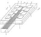
本発明の圧電センサの一例を図面を参照しながら説明する。圧電センサAは、図1及び図2に示したように、一枚の圧電シート1の一面にシグナル電極2が配設されていると共に、上記圧電シート1の他面にはシグナル電極2の電位を測定するための基準電極となるグランド電極4が配設されている。
An example of the piezoelectric sensor of the present invention will be described with reference to the drawings. In the piezoelectric sensor A, as shown in FIGS. 1 and 2, the
本発明の圧電シート1としては、外力が加えられることによって表面に電荷を発生させることができるシート(圧電現象を有するシート)であれば、特に限定されないが、脈波などの微弱な生体信号を精度良く検出でき、感度が高く、厚み方向の変形で電荷を発生しやすいことから、合成樹脂シート(合成樹脂発泡シート又は合成樹脂非発泡シート)に分極を付与した圧電シートが好ましく、合成樹脂発泡シートに分極を付与した圧電シートがより好ましく、ポリオレフィン系樹脂を含む合成樹脂発泡シートに分極を付与した圧電シートが特に好ましい。
The
合成樹脂シートを構成する合成樹脂としては、特に限定されず、例えば、ポリエチレン系樹脂、ポリプロピレン系樹脂などのポリオレフィン系樹脂、ポリフッ化ビニリデン、ポリ乳酸、液晶樹脂などが挙げられ、ポリオレフィン系樹脂が好ましい。 The synthetic resin constituting the synthetic resin sheet is not particularly limited, and examples thereof include polyolefin resins such as polyethylene resins and polypropylene resins, polyvinylidene fluoride, polylactic acid, and liquid crystal resins, and polyolefin resins are preferable. .
合成樹脂シートに分極を付与する方法としては、特に限定されず、例えば、(1)合成樹脂シートを一対の平板電極で挟持し、帯電させたい表面に接触させている平板電極を高圧直流電源に接続すると共に他方の平板電極をアースし、合成樹脂シートに直流又はパルス状の高電圧を印加して合成樹脂に電荷を注入して合成樹脂シートに分極を付与する方法、(2)電子線、X線などの電離性放射線や紫外線を合成樹脂シートの表面に照射して、合成樹脂シートの近傍部の空気分子をイオン化することによって合成樹脂シートに分極を付与する方法、(3)合成樹脂シートの一面に、アースされた平板電極を密着状態に重ね合わせ、合成樹脂シートの他面側に所定間隔を存して直流の高圧電源に電気的に接続された針状電極又はワイヤー電極を配設し、針状電極の先端又はワイヤー電極の表面近傍への電界集中によりコロナ放電を発生させ、空気分子をイオン化させて、針状電極又はワイヤー電極の極性により発生した空気イオンを反発させて合成樹脂に分極を付与する方法などが挙げられる。 The method for imparting polarization to the synthetic resin sheet is not particularly limited. For example, (1) a flat plate electrode sandwiched between a pair of flat plate electrodes and in contact with a surface to be charged is used as a high-voltage DC power source. Connecting and grounding the other plate electrode, applying a direct current or pulsed high voltage to the synthetic resin sheet to inject charges into the synthetic resin, and imparting polarization to the synthetic resin sheet, (2) electron beam, A method of imparting polarization to a synthetic resin sheet by irradiating the surface of the synthetic resin sheet with ionizing radiation such as X-rays or ultraviolet rays to ionize air molecules in the vicinity of the synthetic resin sheet; (3) a synthetic resin sheet; On one side, a grounded flat plate electrode is placed in close contact with each other, and a needle-like electrode or wire electrode electrically connected to a DC high-voltage power source with a predetermined interval on the other side of the synthetic resin sheet The corona discharge is generated by the electric field concentration near the tip of the needle electrode or near the surface of the wire electrode, the air molecules are ionized, and the air ions generated by the polarity of the needle electrode or wire electrode are repelled and synthesized. Examples thereof include a method of imparting polarization to the resin.
圧電シート1の一面1aにはシグナル電極2が必要に応じて固定剤層(図示せず)を介して配設一体化されている。シグナル電極2は、導電性を有しておれば、特に限定されず、例えば、銅箔、アルミニウム箔などの金属シート、導電性膜などが挙げられる。
A
シグナル電極2を導電性膜で構成する場合、圧電シート1の一面1aに汎用の印刷方法を用いて直接形成してもよいが、導電性膜は、通常、電気絶縁シート上に形成された上で、圧電シート1の一面1a上に電気絶縁シートを導電性膜が圧電シート1側となった状態で配設一体化されることが好ましい。圧電シート1又は電気絶縁シート上に導電性膜を形成する方法としては、例えば、(1)圧電シート1又は電気絶縁シート上に、バインダー中に導電性微粒子を含有させてなる導電ペーストを塗布、乾燥させる方法、(2)圧電シート1又は電気絶縁シート上に蒸着によって電極を形成する方法、(3)電気絶縁シートに接着剤などを用いて金属箔を積層一体化させた後、金属箔の不要部分をエッチング法によって除去して電極を形成する方法などが挙げられる。
When the
電気絶縁シートとしては、電気絶縁性を有しておれば、特に限定されず、例えば、ポリエチレンテレフタレートシート、ポリエチレンナフタレートシート、ポリ塩化ビニルシートなどが挙げられる。 The electrical insulating sheet is not particularly limited as long as it has electrical insulating properties, and examples thereof include a polyethylene terephthalate sheet, a polyethylene naphthalate sheet, and a polyvinyl chloride sheet.
固定剤層を構成している固定剤は、反応系・溶剤系・水系・ホットメルト系の接着剤又は粘着剤から構成されており、圧電シート1の感度を維持する観点から、誘電率の低い固定剤が好ましい。
The fixing agent constituting the fixing agent layer is composed of a reaction system, solvent system, water system, hot melt system adhesive or pressure sensitive adhesive, and has a low dielectric constant from the viewpoint of maintaining the sensitivity of the
圧電シート1の一面1aには1個又は複数個のシグナル電極2が互いに電気的に接続されずに独立した状態にて配設又は配設一体化されている。なお、図1においては、複数個のシグナル電極2が碁盤目状に配設されている。
On one surface 1a of the
そして、各シグナル電極2には、圧電シート1にて発生した電荷を電位としてシグナル電極2を通じて圧電センサA外に取り出すための配線部3(以下、シグナル電極に電気的に接続している配線部を「第一配線部」という)が電気的に接続している。各第一配線部3は、圧電シート1の一面1a上に配設又は配設一体化されており、好ましくは、圧電シート1の一面1aの外周端縁に達するまで形成されている。各シグナル電極2に接続している第一配線部3同士も互いに電気的に接続しておらず独立した状態となっている。第一配線部3は、導電性を有しておれば、特に限定されず、例えば、銅箔、アルミニウム箔などの金属シート、導電性膜などが挙げられる。第一配線部3の形成要領は、シグナル電極2の形成要領と同様であるので省略する。
Each
又、圧電シート1の他面1bには、圧電シート1の厚み方向においてシグナル電極2を投影した部分の全てを含む大きさの1個のグランド電極4が、必要に応じて固定剤層(図示せず)を介して、配設又は配設一体化されている。即ち、圧電シート1の他面1bには、圧電シート1の厚み方向においてシグナル電極2を投影した部分にグランド電極4が配設されている。なお、圧電シート1の厚み方向においてシグナル電極2を投影した部分にグランド電極4が配設されていることが好ましく、グランド電極4は複数個に分割されていてもよい。グランド電極4は、シグナル電極2の電位を測定するにあたって基準電極となるように配設されておればよい。なお、固定剤層は上記と同様であるのでその説明を省略する。
In addition, on the other surface 1b of the
グランド電極4は、導電性を有しておれば、特に限定されず、例えば、銅箔、アルミニウム箔などの金属シート、ステンレスなどの金属から形成された金属網、導電性膜などが挙げられる。グランド電極4を導電膜で構成する場合、その要領は、シグナル電極2の場合と同様であるのでその説明を省略する。
If the ground electrode 4 has electroconductivity, it will not specifically limit, For example, the metal net | network formed from metals, such as copper foil and aluminum foil, stainless steel, a conductive film, etc. are mentioned. When the ground electrode 4 is composed of a conductive film, the procedure is the same as in the case of the
そして、各グランド電極4には配線部5(以下、グランド電極に電気的に接続している配線部を「第二配線部」という)が電気的に接続されている。第二配線部5は、圧電シート1の他面1b上に配設又は配設一体化されており、好ましくは、圧電シート1の他面1bの外周端縁に達するまで形成されている。第二配線部5は、導電性を有しておれば、特に限定されず、例えば、銅箔、アルミニウム箔などの金属シート、ステンレスなどの金属から形成された金属網、導電性膜などが挙げられる。第二配線部5の形成要領は、グランド電極4の形成要領と同様であるので省略する。
Each ground electrode 4 is electrically connected to a wiring portion 5 (hereinafter, the wiring portion electrically connected to the ground electrode is referred to as a “second wiring portion”). The second wiring portion 5 is disposed or integrated on the other surface 1b of the
図1では、グランド電極4を圧電シート1の他面1b上にのみ配設一体化している場合を説明したが、図3に示したように、導電性シート6によって圧電シート1を包んだ状態とし、導電性シート6のうち、圧電シート1の他面1b側に配設され且つシグナル電極の電位を測定するにあたって基準電極となる部分61をグランド電極とし、シグナル電極2上に配設された部分62を電磁波シールド層とし、シグナル電極2が外部からの電磁波の影響を受けることを抑制できる構造としてもよい。なお、導電性シート6とシグナル電極2とは、これらの間に電気絶縁シート7などが介在されることによって電気絶縁性が保持されている必要がある。なお、導電性シート6としては、例えば、銅箔、アルミニウム箔などの金属シート、ステンレスなどの金属から形成された金属網、導電性膜などが挙げられる。図1の圧電センサと同様の構成については同一符号を付して説明を省略する。
Although the case where the ground electrode 4 is disposed and integrated only on the other surface 1b of the
又、グランド電極4に接続された第二配線部5は必要に応じて配設されればよく、後述する導電線をグランド電極4に第二配線部を介することなく直接、電気的に接続させてもよい。 Further, the second wiring portion 5 connected to the ground electrode 4 may be provided as necessary, and a conductive wire described later is directly and electrically connected to the ground electrode 4 without passing through the second wiring portion. May be.
更に、圧電シート1において、第一配線部3の配設部分1cの圧電性が低減されている。詳細には、圧電シート1の一面1aに配設された第一配線部3を圧電シート1の厚み方向に投影した圧電シート部分1cの圧電性が低減されている。このように、圧電シート1において、第一配線部3の配設部分の圧電性を低減させることによって、第一配線部3が配設されている圧電シート部分1cに荷重が加わった場合にあっても、第一配線部3が配設されている圧電シート部分1cにおいて電荷が殆ど発生しないように構成し、圧電シート1においてノイズが発生することを効果的に抑制している。
Furthermore, in the
圧電シート1において、第一配線部3の配設部分の圧電性を示す目安として出力感度がある。圧電シート1において、第一配線部3の配設部分の出力感度は、圧電シートにおいてノイズを効果的に抑制できるので、5mV/N以下であり、2mV/N以下が好ましい。一方、圧電シート1において、シグナル電極2の配設部分(シグナル電極2を圧電シート1の厚み方向に投影した圧電シート部分)1dの出力感度は、圧電シートの圧電性に優れているので、10mV/N以上が好ましく、15mV/N以上がより好ましく、20mV/N以上が特に好ましい。なお、圧電シートの出力感度は、圧電シートに10kPaの荷重を30Hzの周波数で加えた時に生ずる出力電圧をいう。圧電シートの出力感度は、例えば、PIEZOTEST社から商品名「Piezometer system PM300」で市販されている装置を用いて圧電シートに10kPaの荷重を30Hzの周波数で加え、その時に生ずる出力電圧をインステック社から商品名「オシロスコープGDS−1000A」にて市販されている装置を用いて測定することができる。
In the
圧電シート1において、第一配線部3の配設部分1cの圧電性を低減する方法としては、特に限定されないが、(1)圧電シートにおける第一配線部を配設する部分1cを60〜120℃に加熱する方法、(2)圧電シートにおける第一配線部を配設する部分1cにコロナ放電処理などの交流放電処理を施す方法が好ましい。具体的には、上記(1)の方法としては、例えば、圧電シートの平面大きさ又はこれよりも大きな大きさを有し且つ圧電シートにおけるシグナル電極の配設部分に対応する部分を切除してなる加熱板を用意し、この加熱板を60〜120℃に加熱した上で加熱板を圧電シートの表面に押圧し、圧電シートにおける第一配線部を配設する部分を60〜120℃に加熱する方法が挙げられる。上記(2)の方法としては、例えば、圧電シート上のシグナル電極を金属箔などの金属シートで保護した後、圧電シートに交流放電処理を施す方法が挙げられる。
In the
上記(1)の方法において、圧電シートにおける第一配線部を配設する部分1cの加熱温度は、圧電シートを損なうことなく、圧電シートにおける第一配線部3の配線部分の圧電性を十分に低減させることができるので、60〜120℃が好ましく、80〜100℃がより好ましい。
In the method of (1) above, the heating temperature of the
次に、上記圧電センサAの使用要領について説明する。圧電センサAにおける各シグナル電極2の第一配線部3に導電線を電気的に接続し、この導電線を測定モジュールに電気的に接続する一方、グランド電極4の第二配線部5に、又は、グランド電極3に直接、導電線を電気的に接続し、グランド電極4に電気的に接続させた導電線を、第一配線部3を接続させている測定モジュールに電気的に接続させる。
Next, how to use the piezoelectric sensor A will be described. A conductive wire is electrically connected to the
圧電シート1がその厚み方向に圧縮されると、圧電シート1内に分極状態で保持された正電荷と負電荷が互いに相対変位することによって圧電シート1に電荷が発生する。圧電シート1にて発生した電荷は電位としてグランド電極4を基準電極としてシグナル電極2を通じて測定される。
When the
この際、圧電シート1における第一配線部3の配設部分1cに荷重が加わった場合にあっても、第一配線部3の配設部分1cの出力感度が5mV/N以下とされて圧電性が低減されていることから、圧電シート1において電荷が殆ど発生することはなく、ノイズは殆ど発生しない。
At this time, even when a load is applied to the
従って、上記圧電センサAによれば、圧電シート1におけるシグナル電極2の配設部分1dに加わった荷重によって発生した電荷を電位として正確に検出することができ、圧電センサAは荷重の検出精度に優れていると共に、荷重を検出したい位置における荷重の有無を正確に検出することができる。
Therefore, according to the piezoelectric sensor A, the electric charge generated by the load applied to the
又、圧電シート1の一面にシグナル電極2を複数個、配設一体化することによって、荷重を検出したい位置における荷重の有無を独立して正確に検出することができるので、圧電シート1に加わる荷重の圧力分布を正確に検出することができると共に、圧電シート1に加わる荷重の変化を正確に捉えることができる。
Further, by arranging and integrating a plurality of
1 圧電シート
1c 圧電シートにおける第一配線部の配設部分
1d 圧電シートにおけるシグナル電極の配設部分
2 シグナル電極
3 第一配線部
4 グランド電極
5 第二配線部
A 圧電センサ
1 Piezoelectric sheet
1c Arrangement part of the first wiring part in the piezoelectric sheet
1d Signal
Claims (3)
Priority Applications (1)
| Application Number | Priority Date | Filing Date | Title |
|---|---|---|---|
| JP2014060329A JP6234858B2 (en) | 2014-03-24 | 2014-03-24 | Piezoelectric sensor |
Applications Claiming Priority (1)
| Application Number | Priority Date | Filing Date | Title |
|---|---|---|---|
| JP2014060329A JP6234858B2 (en) | 2014-03-24 | 2014-03-24 | Piezoelectric sensor |
Publications (2)
| Publication Number | Publication Date |
|---|---|
| JP2015184122A JP2015184122A (en) | 2015-10-22 |
| JP6234858B2 true JP6234858B2 (en) | 2017-11-22 |
Family
ID=54350821
Family Applications (1)
| Application Number | Title | Priority Date | Filing Date |
|---|---|---|---|
| JP2014060329A Active JP6234858B2 (en) | 2014-03-24 | 2014-03-24 | Piezoelectric sensor |
Country Status (1)
| Country | Link |
|---|---|
| JP (1) | JP6234858B2 (en) |
Cited By (1)
| Publication number | Priority date | Publication date | Assignee | Title |
|---|---|---|---|---|
| JP6468403B2 (en) * | 2016-09-21 | 2019-02-13 | 株式会社村田製作所 | Piezoelectric sensor, touch input device |
Families Citing this family (5)
| Publication number | Priority date | Publication date | Assignee | Title |
|---|---|---|---|---|
| EP3739305B1 (en) * | 2016-07-26 | 2023-06-07 | Kistler Holding AG | Wim sensor with sensor package |
| KR102638861B1 (en) * | 2016-09-06 | 2024-02-22 | 세키스이가가쿠 고교가부시키가이샤 | piezoelectric sensor |
| JP7162858B2 (en) * | 2018-02-09 | 2022-10-31 | ロボセンサー技研株式会社 | Planar sensors and how to use them |
| TWI791491B (en) * | 2018-03-02 | 2023-02-11 | 日商積水化學工業股份有限公司 | piezoelectric sensor |
| FR3143260A1 (en) * | 2022-12-09 | 2024-06-14 | Commissariat à l'Energie Atomique et aux Energies Alternatives | PIEZOELECTRIC DEVICE COMPRISING AN ELECTRODE ARRAY |
Family Cites Families (3)
| Publication number | Priority date | Publication date | Assignee | Title |
|---|---|---|---|---|
| JP4008594B2 (en) * | 1997-09-26 | 2007-11-14 | 北陸電気工業株式会社 | Acceleration sensor and triaxial acceleration sensor |
| JP5044196B2 (en) * | 2006-11-13 | 2012-10-10 | アイシン精機株式会社 | Piezoelectric sensor and manufacturing method thereof |
| CN102484199B (en) * | 2010-08-25 | 2014-09-10 | 三井化学株式会社 | Macromolecular piezoelectric material and manufacturing method therefor |
-
2014
- 2014-03-24 JP JP2014060329A patent/JP6234858B2/en active Active
Cited By (2)
| Publication number | Priority date | Publication date | Assignee | Title |
|---|---|---|---|---|
| JP6468403B2 (en) * | 2016-09-21 | 2019-02-13 | 株式会社村田製作所 | Piezoelectric sensor, touch input device |
| JPWO2018056165A1 (en) * | 2016-09-21 | 2019-03-07 | 株式会社村田製作所 | Piezoelectric sensor, touch input device |
Also Published As
| Publication number | Publication date |
|---|---|
| JP2015184122A (en) | 2015-10-22 |
Similar Documents
| Publication | Publication Date | Title |
|---|---|---|
| JP6234858B2 (en) | Piezoelectric sensor | |
| JP6574889B2 (en) | Piezoelectric sensor | |
| JP4613319B2 (en) | Gas radiation detector | |
| TWI669370B (en) | Pressure sensor | |
| JP6013120B2 (en) | Piezoelectric sensor | |
| JP2015533422A5 (en) | ||
| JP6450197B2 (en) | Biological detection system | |
| JP6168891B2 (en) | Biological signal sensor system | |
| CN105036065B (en) | A kind of electret polarization device based on ray and polarization method thereof | |
| JP6279330B2 (en) | Object detection sheet and living body detection system using the same | |
| JP2017058344A (en) | Piezoelectric sensor structure | |
| JP6328955B2 (en) | Biological detection system | |
| JP2015014550A (en) | Piezoelectric sensor sheet original fabric and piezoelectric device | |
| JP6110267B2 (en) | Piezoelectric sensor structure | |
| JP2017151038A (en) | Piezoelectric sensor | |
| JP6126388B2 (en) | Biological signal sensor and biological signal sensor system using the same | |
| JP2014169945A (en) | Piezoelectric sensor | |
| JP2014170863A (en) | Piezoelectric sensor manufacturing method | |
| JP2009296238A5 (en) | ||
| JP2015068643A (en) | Rainfall detection system | |
| JP2017062200A (en) | Piezoelectric sensor structure | |
| JP2015034818A (en) | Piezoelectric sensor | |
| TWI883929B (en) | Touch sensor and display device | |
| JP2015012987A (en) | Biological signal sensor | |
| JP2018159708A (en) | Load detection device |
Legal Events
| Date | Code | Title | Description |
|---|---|---|---|
| A621 | Written request for application examination |
Free format text: JAPANESE INTERMEDIATE CODE: A621 Effective date: 20161104 |
|
| A977 | Report on retrieval |
Free format text: JAPANESE INTERMEDIATE CODE: A971007 Effective date: 20170706 |
|
| A131 | Notification of reasons for refusal |
Free format text: JAPANESE INTERMEDIATE CODE: A131 Effective date: 20170711 |
|
| A521 | Request for written amendment filed |
Free format text: JAPANESE INTERMEDIATE CODE: A523 Effective date: 20170911 |
|
| TRDD | Decision of grant or rejection written | ||
| A01 | Written decision to grant a patent or to grant a registration (utility model) |
Free format text: JAPANESE INTERMEDIATE CODE: A01 Effective date: 20170926 |
|
| A61 | First payment of annual fees (during grant procedure) |
Free format text: JAPANESE INTERMEDIATE CODE: A61 Effective date: 20171025 |
|
| R151 | Written notification of patent or utility model registration |
Ref document number: 6234858 Country of ref document: JP Free format text: JAPANESE INTERMEDIATE CODE: R151 |