JP6236685B2 - Vehicle headlamp - Google Patents

Vehicle headlamp Download PDF

Info

Publication number
JP6236685B2
JP6236685B2 JP2013146708A JP2013146708A JP6236685B2 JP 6236685 B2 JP6236685 B2 JP 6236685B2 JP 2013146708 A JP2013146708 A JP 2013146708A JP 2013146708 A JP2013146708 A JP 2013146708A JP 6236685 B2 JP6236685 B2 JP 6236685B2
Authority
JP
Japan
Prior art keywords
light
lens
lens unit
distribution pattern
light distribution
Prior art date
Legal status (The legal status is an assumption and is not a legal conclusion. Google has not performed a legal analysis and makes no representation as to the accuracy of the status listed.)
Active
Application number
JP2013146708A
Other languages
Japanese (ja)
Other versions
JP2015018761A (en
Inventor
大久保 泰宏
泰宏 大久保
Current Assignee (The listed assignees may be inaccurate. Google has not performed a legal analysis and makes no representation or warranty as to the accuracy of the list.)
Ichikoh Industries Ltd
Original Assignee
Ichikoh Industries Ltd
Priority date (The priority date is an assumption and is not a legal conclusion. Google has not performed a legal analysis and makes no representation as to the accuracy of the date listed.)
Filing date
Publication date
Application filed by Ichikoh Industries Ltd filed Critical Ichikoh Industries Ltd
Priority to JP2013146708A priority Critical patent/JP6236685B2/en
Publication of JP2015018761A publication Critical patent/JP2015018761A/en
Application granted granted Critical
Publication of JP6236685B2 publication Critical patent/JP6236685B2/en
Active legal-status Critical Current
Anticipated expiration legal-status Critical

Links

Images

Landscapes

  • Non-Portable Lighting Devices Or Systems Thereof (AREA)

Description

この発明は、半導体型光源からの光をレンズから所定の配光パターンとして車両の前方に照射するレンズ直射型の車両用前照灯に関するものである。   The present invention relates to a direct lens-type vehicle headlamp that irradiates light from a semiconductor-type light source to the front of a vehicle as a predetermined light distribution pattern from a lens.

この種の車両用前照灯は、従来からある(たとえば、特許文献1、特許文献2)。以下、従来の車両用前照灯について説明する。   This type of vehicle headlamp has been conventionally used (for example, Patent Document 1 and Patent Document 2). Hereinafter, a conventional vehicle headlamp will be described.

特許文献1の従来の車両用前照灯は、発光素子光源と、投影レンズと、シェードとを、備えるダイレクトプロジェクション方式のものである。発光素子光源からの光の一部をシェードで遮蔽して、残りの光を投影レンズからカットオフラインを有するすれ違い配光パターンとして車両の前方に照射するものである。   The conventional vehicular headlamp of Patent Document 1 is a direct projection system that includes a light emitting element light source, a projection lens, and a shade. A part of light from the light emitting element light source is shielded by a shade, and the remaining light is irradiated from the projection lens to the front of the vehicle as a passing light distribution pattern having a cut-off line.

特許文献2の従来の車両用前照灯は、発光ユニットと、投影レンズと、シェードを含む光学部材と、を備える直射型のものである。発光ユニットからの光の一部をシェードと遮蔽して、残りの光を投影レンズからロービームとして車両の前方に照射される。   The conventional vehicular headlamp disclosed in Patent Document 2 is a direct-lighting type including a light emitting unit, a projection lens, and an optical member including a shade. A part of the light from the light emitting unit is shielded from the shade, and the remaining light is irradiated from the projection lens as a low beam to the front of the vehicle.

特開2011−187305号公報JP 2011-187305 A 特開2012−18839号公報JP 2012-18839 A

ところが、特許文献1の従来の車両用前照灯は、シェードの一部が発光素子光源と投影レンズとの間に位置するときに、発光素子光源からの光がシェードの一部の光軸に向き合う面で反射して投影レンズに入射すると、配光制御されていない光が投影レンズから迷光として照射される。また、同じく、特許文献2の従来の車両用前照灯は、シェードの一部が発光ユニットと投影レンズとの間に位置するときに、発光ユニットからの光がシェードの一部の光軸に向き合う面で反射して投影レンズに入射すると、配光制御されていない光が投影レンズから迷光として照射される。そして、迷光が集中すると、グレアとなる場合がある。   However, in the conventional vehicle headlamp of Patent Document 1, when a part of the shade is positioned between the light emitting element light source and the projection lens, the light from the light emitting element light source is placed on the optical axis of a part of the shade. When the light is reflected by the facing surfaces and enters the projection lens, light that is not subjected to light distribution control is emitted from the projection lens as stray light. Similarly, in the conventional vehicle headlamp disclosed in Patent Document 2, when a part of the shade is positioned between the light emitting unit and the projection lens, the light from the light emitting unit is placed on the optical axis of a part of the shade. When the light is reflected by the facing surfaces and enters the projection lens, light that is not subjected to light distribution control is emitted from the projection lens as stray light. If stray light is concentrated, glare may occur.

この発明が解決しようとする課題は、従来の車両用前照灯では、投影レンズから照射される迷光によりグレアが発生する場合がある、という点にある。   The problem to be solved by the present invention is that glare may occur in the conventional vehicle headlamp due to stray light emitted from the projection lens.

この発明(請求項1にかかる発明)は、半導体型光源と、半導体型光源の発光面からの光を所定の配光パターンとして車両の前方に照射するレンズと、発光面からの光の一部が入射される入射面と入射面に入射された光をレンズに向けて出射する出射面とが設けられた可変焦点レンズ部を有する光制御部材と、を備え、光制御部材の一部は、発光面を含む面、および、レンズの入射面、および、レンズの縁を通りレンズの基準光軸と平行もしくはほぼ平行な筒面により囲まれた空間中に配置されていて、光制御部材の一部のうち、可変焦点レンズ部の入射面と可変焦点レンズ部の出射面との間の面であって基準光軸に向き合う面には、光拡散部が設けられている、ことを特徴とする。 The present invention (the invention according to claim 1) includes a semiconductor-type light source, a lens that irradiates the front of the vehicle with light from the light-emitting surface of the semiconductor-type light source as a predetermined light distribution pattern, and a part of the light from the light-emitting surface. A light control member having a variable focus lens portion provided with an incident surface on which light is incident and an exit surface that emits light incident on the incident surface toward the lens, and a part of the light control member includes: The light control member is disposed in a space surrounded by a surface including the light emitting surface, a lens incident surface, and a cylindrical surface that passes through the lens edge and is parallel or substantially parallel to the reference optical axis of the lens. The light diffusing unit is provided on a surface between the incident surface of the variable focus lens unit and the output surface of the variable focus lens unit and facing the reference optical axis. .

この発明(請求項2にかかる発明)は、光制御部材が、駆動部材により、一部が空間中に配置されている第1位置と、第2位置とに移動切替可能に位置する、ことを特徴とする。   According to the present invention (the invention according to claim 2), the light control member is positioned to be movable and switched between a first position and a second position, a part of which is disposed in the space, by the driving member. Features.

この発明(請求項3にかかる発明)は、光制御部材が第1位置に位置するときには、光拡散部が基準光軸よりも下側に位置し、発光面からの光であって光拡散部で反射された光が、レンズから基準光軸より上向きに照射される、ことを特徴とする。   In the present invention (the invention according to claim 3), when the light control member is located at the first position, the light diffusing portion is located below the reference optical axis, and the light diffusing portion is light from the light emitting surface. The light reflected by is irradiated upward from the reference optical axis from the lens.

この発明は、光制御部材が、可変焦点レンズ部を備える、ことを特徴とする。 The inventions, the light control member includes a varifocal lens unit, characterized in that.

この発明(請求項にかかる発明)は、光拡散部が、プリズム素子の群からなり、プリズム素子の軸が、発光面からの光の放射方向もしくはほぼ放射方向に位置する、ことを特徴とする。 This invention (invention according to claim 4 ) is characterized in that the light diffusing section is composed of a group of prism elements, and the axis of the prism elements is located in the radiation direction or almost the radiation direction of light from the light emitting surface. To do.

この発明の車両用前照灯は、発光面からの光が光制御部材の一部のうち基準光軸に向き合う面の光拡散部で散らばって(拡散して)反射する。このために、配光制御されていない光がレンズから迷光として照射されたとしても、その迷光は散らばっているので、グレアとなるようなことがない。このように、レンズから照射される迷光によりグレアが発生する場合がない。   In the vehicle headlamp according to the present invention, light from the light emitting surface is scattered (diffused) and reflected by the light diffusing portion on the surface of the light control member facing the reference optical axis. For this reason, even if light that is not subjected to light distribution control is irradiated as stray light from the lens, the stray light is scattered, and thus there is no glare. Thus, there is no case where glare is generated by stray light emitted from the lens.

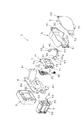
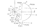
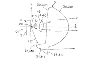
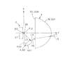
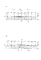
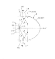
図1は、この発明にかかる車両用前照灯の実施形態1を示すランプユニットの主要構成部品の分解斜視図である。1 is an exploded perspective view of main components of a lamp unit showing Embodiment 1 of a vehicle headlamp according to the present invention. 図2は、ランプユニットを示す斜視図である。FIG. 2 is a perspective view showing the lamp unit. 図3は、ランプユニットを示す正面図である。FIG. 3 is a front view showing the lamp unit. 図4は、光制御部材が第1位置に位置しているときの光路を示す説明図(図3におけるIV−IV線断面図に対応する説明図)である。FIG. 4 is an explanatory diagram (an explanatory diagram corresponding to the cross-sectional view taken along the line IV-IV in FIG. 3) illustrating the optical path when the light control member is located at the first position. 図5は、光制御部材が第2位置に位置しているときの光路を示す説明図(図3におけるIV−IV線断面図に対応する説明図)である。FIG. 5 is an explanatory diagram showing an optical path when the light control member is located at the second position (an explanatory diagram corresponding to the sectional view taken along the line IV-IV in FIG. 3). 図6は、発光面からの光が光拡散部において散らばって反射する状態を示す光路の説明図である。FIG. 6 is an explanatory diagram of an optical path showing a state in which light from the light emitting surface is scattered and reflected by the light diffusion portion. 図7は、光が光拡散部において散らばって反射する状態と散らばらずに反射する状態とを示す光路の説明図である。FIG. 7 is an explanatory diagram of an optical path showing a state in which light is scattered and reflected by the light diffusion portion and a state in which light is reflected without being scattered. 図8は、ロービーム用配光パターンとハイビーム用配光パターンとを示す等光度曲線の説明図である。FIG. 8 is an explanatory diagram of an isoluminous curve showing a low beam distribution pattern and a high beam distribution pattern. 図9は、散らばっている状態の迷光と散らばっていない状態の迷光とを示す説明図である。FIG. 9 is an explanatory diagram showing stray light in a scattered state and stray light in a non-scattered state. 図10は、この発明にかかる車両用前照灯の実施形態2を示す光路の説明図(図6に対応する説明図)である。FIG. 10 is an explanatory diagram of an optical path (an explanatory diagram corresponding to FIG. 6) showing a second embodiment of the vehicle headlamp according to the present invention.

以下、この発明にかかる車両用前照灯の実施形態(実施例)の2例を図面に基づいて詳細に説明する。なお、この実施形態によりこの発明が限定されるものではない。図8、図9において、符号「VU−VD」は、スクリーンの上下の垂直線を示す。符号「HL−HR」は、スクリーンの左右の水平線を示す。また、図8は、コンピュータシミュレーションにより作図されたスクリーン上の配光パターンを簡略化して示す等光度曲線の説明図である。この等光度曲線の説明図において、中央の等光度曲線は、高光度を示し、外側の等光度曲線は、低光度を示す。さらに、図4、図5、図6、図10において、レンズおよび光制御部材の断面のハッチングは、省略してある。この明細書および別紙の特許請求の範囲において、前、後、上、下、左、右は、この発明にかかる車両用前照灯を車両に搭載した際の前、後、上、下、左、右である。   Hereinafter, two examples of embodiments (examples) of a vehicle headlamp according to the present invention will be described in detail with reference to the drawings. In addition, this invention is not limited by this embodiment. In FIGS. 8 and 9, the symbol “VU-VD” indicates vertical lines on the upper and lower sides of the screen. Reference sign “HL-HR” indicates horizontal lines on the left and right of the screen. FIG. 8 is an explanatory diagram of an isoluminous curve showing a simplified light distribution pattern on the screen drawn by computer simulation. In the explanatory diagram of the isoluminous curve, the central isoluminous curve indicates high luminous intensity, and the outer isoluminous curve indicates low luminous intensity. Furthermore, in FIG. 4, FIG. 5, FIG. 6, FIG. 10, the hatching of the cross section of the lens and the light control member is omitted. In this specification and the appended claims, front, rear, upper, lower, left, and right are front, rear, upper, lower, and left when the vehicle headlamp according to the present invention is mounted on a vehicle. , Right.

(実施形態1の構成の説明)
図1〜図9は、この発明にかかる車両用前照灯の実施形態1を示す。以下、この実施形態1にかかる車両用前照灯の構成について説明する。図1中、符号1は、この実施形態1にかかる車両用前照灯(たとえば、ヘッドランプなど)である。前記車両用前照灯1は、車両の前部の左右両端部に搭載されている。
(Description of Configuration of Embodiment 1)
1 to 9 show Embodiment 1 of a vehicle headlamp according to the present invention. Hereinafter, the configuration of the vehicle headlamp according to the first embodiment will be described. In FIG. 1, reference numeral 1 denotes a vehicle headlamp (for example, a headlamp) according to the first embodiment. The vehicle headlamp 1 is mounted on both left and right ends of the front portion of the vehicle.

(ランプユニットの説明)
前記車両用前照灯1は、図1〜図3に示すように、ランプハウジング(図示せず)と、ランプレンズ(図示せず)と、半導体型光源2と、レンズ(固定レンズ)3と、光制御部材(可動レンズ)4と、駆動部材5と、レンズカバー部材6と、軸受部材7と、ベース部材8と、冷却部材9と、を備えるものである。
(Explanation of lamp unit)
As shown in FIGS. 1 to 3, the vehicle headlamp 1 includes a lamp housing (not shown), a lamp lens (not shown), a semiconductor light source 2, and a lens (fixed lens) 3. , A light control member (movable lens) 4, a drive member 5, a lens cover member 6, a bearing member 7, a base member 8, and a cooling member 9.

前記半導体型光源2および前記レンズ3および前記光制御部材4および前記駆動部材5および前記レンズカバー部材6および前記軸受部材7および前記ベース部材8および前記冷却部材9は、ランプユニットを構成する。前記ランプハウジングおよび前記ランプレンズは、灯室(図示せず)を画成する。前記ランプユニット2、3、4、5、6、7、8、9は、前記灯室内に配置されていて、かつ、上下方向用光軸調整機構(図示せず)および左右方向用光軸調整機構(図示せず)を介して前記ランプハウジングに取り付けられている。   The semiconductor-type light source 2, the lens 3, the light control member 4, the drive member 5, the lens cover member 6, the bearing member 7, the base member 8, and the cooling member 9 constitute a lamp unit. The lamp housing and the lamp lens define a lamp chamber (not shown). The lamp units 2, 3, 4, 5, 6, 7, 8, and 9 are disposed in the lamp chamber, and have an optical axis adjustment mechanism for vertical direction (not shown) and an optical axis adjustment for horizontal direction. It is attached to the lamp housing via a mechanism (not shown).

(半導体型光源2の説明)
前記半導体型光源2は、図1、図4〜図7に示すように、この例では、たとえば、LED、OELまたはOLED(有機EL)などの自発光半導体型光源である。前記半導体型光源2は、発光チップ(LEDチップ)20と、前記発光チップ20を封止樹脂部材で封止したパッケージ(LEDパッケージ)と、前記パッケージを実装した基板21と、前記基板21に取り付けられていて前記発光チップ20に電源(バッテリー)からの電流を供給するコネクタ22と、から構成されている。なお、図4〜図7においては、前記コネクタ22の図示を省略してある。
(Description of the semiconductor-type light source 2)
As shown in FIGS. 1 and 4 to 7, the semiconductor light source 2 is a self-luminous semiconductor light source such as an LED, an OEL, or an OLED (organic EL) in this example. The semiconductor light source 2 includes a light emitting chip (LED chip) 20, a package (LED package) in which the light emitting chip 20 is sealed with a sealing resin member, a substrate 21 on which the package is mounted, and an attachment to the substrate 21. And a connector 22 for supplying a current from a power source (battery) to the light emitting chip 20. 4 to 7, illustration of the connector 22 is omitted.

前記基板21は、位置決め孔および位置決めピンなどにより前記ベース部材8の光源取付部80に位置決めされ、かつ、スクリューなどにより、前記ベース部材8の前記光源取付部80に取り付けられている。この結果、前記半導体型光源2は、前記ベース部材8に取り付けられている。   The substrate 21 is positioned on the light source mounting portion 80 of the base member 8 by positioning holes and positioning pins, and is mounted on the light source mounting portion 80 of the base member 8 by screws or the like. As a result, the semiconductor light source 2 is attached to the base member 8.

前記発光チップ20は、この例では、平面矩形形状(平面長方形状)をなす。すなわち、4個の正方形のチップをX軸方向(水平方向)に配列してなるものである。なお、2個もしくは3個もしくは5個以上の正方形のチップ、あるいは、1個の長方形のチップ、あるいは、1個の正方形のチップ、を使用しても良い。前記発光チップ20の正面この例では長方形の正面が発光面23をなす。前記発光面23は、前記レンズ3の基準光軸(基準軸)Zの前側に向いている。前記発光チップ20の前記発光面23の中心Oは、前記レンズ3の基準焦点Fもしくはその近傍に位置し、かつ、前記レンズ3の基準光軸Z上もしくはその近傍に位置する。   In this example, the light emitting chip 20 has a planar rectangular shape (planar rectangular shape). That is, four square chips are arranged in the X-axis direction (horizontal direction). Two, three, or five or more square chips, one rectangular chip, or one square chip may be used. Front of the light emitting chip 20 In this example, the rectangular front forms the light emitting surface 23. The light emitting surface 23 faces the front side of the reference optical axis (reference axis) Z of the lens 3. The center O of the light emitting surface 23 of the light emitting chip 20 is located at or near the reference focal point F of the lens 3 and on or near the reference optical axis Z of the lens 3.

図において、X、Y、Zは、直交座標(X−Y−Z直交座標系)を構成する。X軸は、前記発光チップ20の前記発光面23の中心Oを通る左右方向の水平軸であって、この実施形態1において、右側が+方向であり、左側が−方向である。また、Y軸は、前記発光チップ20の前記発光面23の中心Oを通る上下方向の鉛直軸であって、この実施形態1において、上側が+方向であり、下側が−方向である。さらに、Z軸は、前記発光チップ20の前記発光面23の中心Oを通る法線(垂線)、すなわち、前記X軸および前記Y軸と直交する前後方向の軸であって、この実施形態1において、前側が+方向であり、後側が−方向である。   In the figure, X, Y, and Z constitute an orthogonal coordinate (XYZ orthogonal coordinate system). The X axis is a horizontal axis in the left-right direction that passes through the center O of the light emitting surface 23 of the light emitting chip 20. In the first embodiment, the right side is the + direction and the left side is the-direction. The Y axis is a vertical axis in the vertical direction passing through the center O of the light emitting surface 23 of the light emitting chip 20, and in the first embodiment, the upper side is the + direction and the lower side is the-direction. Further, the Z axis is a normal line (perpendicular) passing through the center O of the light emitting surface 23 of the light emitting chip 20, that is, an axis in the front-rear direction orthogonal to the X axis and the Y axis. , The front side is the + direction and the rear side is the − direction.

(レンズ3の説明)
前記レンズ3は、光透過性部材から構成されている。前記レンズ3は、図1〜図6に示すように、主レンズ部30と、補助レンズ部(付加レンズ部)31と、取付部32と、から構成されている。前記取付部32は、前記主レンズ部30の左右両端部に一体に設けられている。前記取付部32は、前記レンズカバー部材6を介して位置決め孔および位置決めピンなどにより前記ベース部材8のレンズ取付部81に位置決めされ、かつ、スクリューなどにより、前記ベース部材8の前記レンズ取付部81に取り付けられている。この結果、前記レンズ3は、前記レンズカバー部材6を介して前記ベース部材8に取り付けられている。前記取付部32は、この例では、前記レンズ3と一体構造であるが、前記レンズ3と別体構造であっても良い。
(Description of lens 3)
The lens 3 is composed of a light transmissive member. As shown in FIGS. 1 to 6, the lens 3 includes a main lens part 30, an auxiliary lens part (additional lens part) 31, and an attachment part 32. The attachment portion 32 is integrally provided at both left and right end portions of the main lens portion 30. The mounting portion 32 is positioned on the lens mounting portion 81 of the base member 8 by a positioning hole and a positioning pin through the lens cover member 6, and the lens mounting portion 81 of the base member 8 by a screw or the like. Is attached. As a result, the lens 3 is attached to the base member 8 via the lens cover member 6. In this example, the attachment portion 32 has an integral structure with the lens 3, but may have a separate structure from the lens 3.

前記レンズ3は、前記半導体型光源2からの光を、図8(A)に示す第1配光パターンとしてのロービーム用配光パターン(すれ違い用配光パターン)LP、および、図8(B)に示す第2配光パターンとしてのハイビーム用配光パターン(走行用配光パターン)HPとして車両の前方に照射するものである。前記ロービーム用配光パターンLPは、下水平カットオフラインCL1と、斜めカットオフラインCL2と、上水平カットオフラインCL3とを、有する。前記ハイビーム用配光パターンHPは、中央部にホットゾーン(高光度帯)HZを有する。   The lens 3 converts the light from the semiconductor-type light source 2 into a low beam light distribution pattern (passing light distribution pattern) LP as a first light distribution pattern shown in FIG. 8A, and FIG. 8B. The light distribution pattern for high beams (running light distribution pattern) HP as the second light distribution pattern shown in FIG. The low-beam light distribution pattern LP includes a lower horizontal cut-off line CL1, an oblique cut-off line CL2, and an upper horizontal cut-off line CL3. The high beam light distribution pattern HP has a hot zone (high luminous intensity band) HZ at the center.

(主レンズ部30の説明)
前記主レンズ部30は、図4、図5に示すように、前記基準光軸Zおよび前記基準焦点Fを有する。前記主レンズ部30は、前記半導体型光源2から放射される光のうち、中央光L1および周辺光の一部を利用するものである。前記中央光L1は、前記半導体型光源2の半球放射範囲のX軸もしくはY軸から所定の角度(この例では、約60°)以上の範囲の光であって、前記主レンズ部30の中央部に入射する光である。また、前記周辺光は、前記半導体型光源2の半球放射範囲のX軸もしくはY軸から所定の角度(この例では、約60°)以下の範囲の光である。前記周辺光の一部は、前記周辺光のうち前記主レンズ部30の周辺部に入射する光である。前記主レンズ部30は、この例では、前記半導体型光源2からの光を透過させる透過タイプのレンズ部である。
(Description of the main lens unit 30)
The main lens unit 30 has the reference optical axis Z and the reference focal point F as shown in FIGS. The main lens unit 30 uses the central light L1 and a part of the ambient light among the light emitted from the semiconductor light source 2. The central light L1 is light having a predetermined angle (in this example, about 60 °) or more from the X-axis or Y-axis of the hemispherical emission range of the semiconductor-type light source 2, and is the center of the main lens unit 30. It is light incident on the part. The ambient light is light having a predetermined angle (about 60 ° in this example) or less from the X axis or Y axis of the hemispherical emission range of the semiconductor light source 2. A part of the ambient light is light that is incident on a peripheral part of the main lens unit 30 in the peripheral light. In this example, the main lens unit 30 is a transmissive lens unit that transmits light from the semiconductor light source 2.

前記主レンズ部30は、前記半導体型光源2からの光(前記中央光L1および前記周辺光の一部)を主配光パターン(基本配光パターン)、この実施形態1においては、ロービーム用配光パターンの主配光パターン、および、ハイビーム用配光パターンの主配光パターン、として車両の前方に照射する。すなわち、前記主レンズ部30は、前記半導体型光源2からの直接入射した光(前記中央光L1および前記周辺光の一部)を前記ロービーム用配光パターンの主配光パターンとして車両の前方に照射し、かつ、前記半導体型光源2から前記光制御部材4を透過した光(前記中央光L1、および、X軸方向の前記周辺光の一部)および前記半導体型光源2からの直接入射した光(X軸方向の前記周辺光の一部を除いた残りの前記周辺光の一部)を前記ハイビーム用配光パターンの主配光パターンとして車両の前方に照射する。   The main lens unit 30 uses the light from the semiconductor-type light source 2 (the central light L1 and a part of the ambient light) as a main light distribution pattern (basic light distribution pattern). The light is irradiated in front of the vehicle as the main light distribution pattern of the light pattern and the main light distribution pattern of the high beam light distribution pattern. That is, the main lens unit 30 uses the light directly incident from the semiconductor light source 2 (the central light L1 and part of the ambient light) as the main light distribution pattern of the low beam light distribution pattern in front of the vehicle. Irradiated and transmitted through the light control member 4 from the semiconductor-type light source 2 (the central light L1 and part of the ambient light in the X-axis direction) and directly incident from the semiconductor-type light source 2 Light (a part of the remaining ambient light excluding the part of the ambient light in the X-axis direction) is irradiated in front of the vehicle as a main light distribution pattern of the high beam light distribution pattern.

前記主レンズ部30は、前記半導体型光源2からの光が前記主レンズ部30中に入射する入射面300と、前記主レンズ部30中に入射した光が出射する出射面301と、から構成されている。前記主レンズ部30の前記入射面300は、自由曲面あるいは複合2次曲面から構成されている。前記主レンズ部30の前記出射面301は、前記半導体型光源2と反対側に突出した凸形状をなし、自由曲面あるいは複合2次曲面から構成されている。   The main lens unit 30 includes an incident surface 300 on which light from the semiconductor-type light source 2 enters the main lens unit 30 and an output surface 301 on which light incident on the main lens unit 30 exits. Has been. The entrance surface 300 of the main lens unit 30 is composed of a free-form surface or a composite quadric surface. The exit surface 301 of the main lens portion 30 has a convex shape protruding to the opposite side of the semiconductor light source 2, and is composed of a free curved surface or a compound quadratic curved surface.

(補助レンズ部31の説明)
前記補助レンズ部31は、図4、図5に示すように、前記主レンズ部30の周辺この実施形態1においては下辺(下側)に設けられている。この結果、前記半導体型光源2と、前記レンズ3の上部との間には、開口部が形成されている。
(Description of the auxiliary lens unit 31)
As shown in FIGS. 4 and 5, the auxiliary lens portion 31 is provided around the main lens portion 30 on the lower side (lower side) in the first embodiment. As a result, an opening is formed between the semiconductor-type light source 2 and the upper portion of the lens 3.

前記補助レンズ部31は、前記半導体型光源2から放射される光のうち、周辺光の他の一部L2を有効利用するものである。前記周辺光の他の一部L2は、前記周辺光のうち前記補助レンズ部31に入射する光である。前記補助レンズ部31は、この例では、前記周辺光の他の一部L2を全反射させる全反射タイプのレンズ部である。前記補助レンズ部31は、前記主レンズ部30と一体のものである。   The auxiliary lens unit 31 effectively uses another part L2 of ambient light among the light emitted from the semiconductor-type light source 2. The other part L2 of the ambient light is light that is incident on the auxiliary lens unit 31 among the ambient light. In this example, the auxiliary lens portion 31 is a total reflection type lens portion that totally reflects the other part L2 of the ambient light. The auxiliary lens unit 31 is integral with the main lens unit 30.

前記補助レンズ部31は、前記周辺光の他の一部L2を補助配光パターン、この実施形態1においては、ロービーム用配光パターンの補助配光パターン、および、ハイビーム用配光パターンの補助配光パターン、として車両の前方に照射する。すなわち、前記補助レンズ部31は、前記半導体型光源2から前記光制御部材4を透過した光(前記周辺光の他の一部L2)を前記ロービーム用配光パターンの補助配光パターンとして車両の前方に照射し、かつ、前記半導体型光源2からの直接入射した光(前記周辺光の他の一部L2)を前記ハイビーム用配光パターンの補助配光パターンとして車両の前方に照射する。   The auxiliary lens unit 31 uses the auxiliary light distribution pattern of the other portion L2 of the ambient light as an auxiliary light distribution pattern. Irradiate the front of the vehicle as a light pattern. In other words, the auxiliary lens unit 31 uses the light transmitted through the light control member 4 from the semiconductor light source 2 (the other part L2 of the ambient light) as an auxiliary light distribution pattern of the low beam light distribution pattern. Irradiate forward and directly incident light from the semiconductor-type light source 2 (the other part L2 of the ambient light) is irradiated forward of the vehicle as an auxiliary light distribution pattern of the high beam light distribution pattern.

前記補助レンズ部31は、前記周辺光の他の一部L2が前記補助レンズ部31中に入射する入射面310と、前記入射面310から前記補助レンズ部31中に入射した光が反射する反射面311と、前記反射面311で反射した反射光が前記補助レンズ部31中から外部に出射する出射面312と、から構成されている。前記入射面310および前記反射面311および前記出射面312は、それぞれ自由曲面(あるいは複合二次曲面)から構成されている。   The auxiliary lens unit 31 includes an incident surface 310 on which another part L2 of the ambient light is incident on the auxiliary lens unit 31, and a reflection on which light incident on the auxiliary lens unit 31 from the incident surface 310 is reflected. A surface 311 and an exit surface 312 from which reflected light reflected by the reflecting surface 311 exits from the auxiliary lens portion 31 to the outside are configured. The entrance surface 310, the reflection surface 311 and the exit surface 312 are each composed of a free-form surface (or a composite quadric surface).

(光制御部材4の説明)
前記光制御部材4は、中央側の部分の可変焦点レンズ部40と、左右両側の部分の取付部41と、を備える。前記可変焦点レンズ部40と前記取付部41とは、光透過部材から構成されていて、一体構造をなす。前記取付部41は、前記軸受部材7を介して前記ベース部材8に位置決めされて取り付けられている。この結果、前記光制御部材4は、前記軸受部材7を介して前記ベース部材8に、第1位置と第2位置との間を回転可能に取り付けられている。前記光制御部材4の回転中心O1は、前記発光面23の中心Oよりも、後側でかつ下側に位置する。
(Description of light control member 4)
The light control member 4 includes a varifocal lens portion 40 at a central portion and mounting portions 41 at both left and right portions. The varifocal lens portion 40 and the attachment portion 41 are made of a light transmitting member and have an integral structure. The attachment portion 41 is positioned and attached to the base member 8 via the bearing member 7. As a result, the light control member 4 is attached to the base member 8 via the bearing member 7 so as to be rotatable between a first position and a second position. The rotation center O <b> 1 of the light control member 4 is located behind and below the center O of the light emitting surface 23.

前記光制御部材4は、前記駆動部材5により前記第1位置と前記第2位置とに移動(回転)切替可能に構成されている。前記第1位置は、図4に示すように、前記可変焦点レンズ部40が前記半導体型光源2の前記発光面23と、前記補助レンズ部31の前記入射面310との間に位置する位置である。前記第2位置は、図5に示すように、前記可変焦点レンズ部40が前記半導体型光源2の前記発光面23と、前記主レンズ部30の前記入射面300の前記中央光L1が入射する中央部との間に位置する位置である。   The light control member 4 is configured to be switchable (rotated) between the first position and the second position by the drive member 5. As shown in FIG. 4, the first position is a position where the variable focus lens unit 40 is located between the light emitting surface 23 of the semiconductor light source 2 and the incident surface 310 of the auxiliary lens unit 31. is there. As shown in FIG. 5, the varifocal lens unit 40 is incident on the light emitting surface 23 of the semiconductor light source 2 and the central light L <b> 1 on the incident surface 300 of the main lens unit 30. It is a position located between the central part.

前記第1位置に位置する前記光制御部材4の前記可変焦点レンズ部40と前記レンズ3の前記補助レンズ部31とは、図4に示すように、一部(大部分)が上下において重なる。この結果、前記半導体型光源2と、前記レンズ3の下部および前記光制御部材4との間には、若干の開口部が形成されている。   As shown in FIG. 4, a part (most part) of the variable focus lens part 40 of the light control member 4 and the auxiliary lens part 31 of the lens 3 overlap each other in the vertical direction. As a result, a slight opening is formed between the semiconductor-type light source 2 and the lower portion of the lens 3 and the light control member 4.

(可変焦点レンズ部40の説明)
前記可変焦点レンズ部40は、前記第1位置に位置するときには、図4に示すように、前記周辺光の他の一部L2を透過させて前記補助レンズ部31中に入射させる。この結果、前記ロービーム用配光パターンの補助配光パターンが前記補助レンズ部31の前記出射面312から車両の前方に照射される。
(Description of the variable focus lens unit 40)
When the varifocal lens unit 40 is located at the first position, as shown in FIG. 4, the other part L <b> 2 of the ambient light is transmitted and incident into the auxiliary lens unit 31. As a result, the auxiliary light distribution pattern of the low beam light distribution pattern is irradiated from the emission surface 312 of the auxiliary lens unit 31 to the front of the vehicle.

前記可変焦点レンズ部40は、前記第2位置に位置するときには、図5に示すように、前記中央光L1を透過させて前記主レンズ部30の中央部中に入射させる。この結果、前記ハイビーム用配光パターンの主配光パターンが前記主レンズ部30の前記出射面301の中央部から車両の前方に照射される。   When the varifocal lens unit 40 is located at the second position, as shown in FIG. 5, the varifocal lens unit 40 transmits the central light L <b> 1 and enters the central part of the main lens unit 30. As a result, the main light distribution pattern of the high beam light distribution pattern is irradiated from the center of the exit surface 301 of the main lens unit 30 to the front of the vehicle.

図1、図4、図5に示すように、前記可変焦点レンズ部40の入射面400は、前記可変焦点レンズ部40の光軸(光出射軸)方向に、すなわち、前記半導体型光源2の前記発光面23に対して前記可変焦点レンズ部40の内側に凹形状をなす。前記可変焦点レンズ部40の出射面401は、前記可変焦点レンズ部40の光軸(光出射軸)方向に、すなわち、前記半導体型光源2の前記発光面23に対して前記可変焦点レンズ部40の外側に凸形状をなす。   As shown in FIGS. 1, 4, and 5, the incident surface 400 of the varifocal lens unit 40 is in the optical axis (light emission axis) direction of the varifocal lens unit 40, that is, the semiconductor-type light source 2. A concave shape is formed inside the varifocal lens portion 40 with respect to the light emitting surface 23. The exit surface 401 of the varifocal lens unit 40 is in the optical axis (light exit axis) direction of the varifocal lens unit 40, that is, with respect to the light emitting surface 23 of the semiconductor-type light source 2. Convex shape outside.

前記可変焦点レンズ部40は、前記補助レンズ部31の焦点を変化させるものである。すなわち、前記第1位置に位置するときの前記補助レンズ部31の焦点(疑似焦点)F1を、前記第2位置に位置するときの前記補助レンズ部31の焦点Fに対して、上側かつ右側に変位させるものである。前記疑似焦点F1は、前記可変焦点レンズ部40を通した前記補助レンズ部31の疑似焦点である。   The variable focus lens unit 40 changes the focus of the auxiliary lens unit 31. That is, the focal point (pseudo focal point) F1 of the auxiliary lens unit 31 when positioned at the first position is on the upper side and the right side with respect to the focal point F of the auxiliary lens unit 31 when positioned at the second position. It is to be displaced. The pseudo focus F <b> 1 is a pseudo focus of the auxiliary lens unit 31 through the variable focus lens unit 40.

前記可変焦点レンズ部40は、水平断面において、対向車線側この例では右側から走行車線側この例では左側にかけて徐々に前記入射面400と前記出射面401との間の距離が近くなる。すなわち、前記可変焦点レンズ部40の右側端部の前記入射面400と前記出射面401との間の距離は長く、前記可変焦点レンズ部40の左側端部の前記入射面400と前記出射面401との間の距離は短い。   In the horizontal section, the variable focus lens portion 40 gradually decreases in distance from the incident surface 400 and the exit surface 401 from the right side in this example to the left side in this example. That is, the distance between the entrance surface 400 and the exit surface 401 at the right end of the variable focus lens unit 40 is long, and the entrance surface 400 and the exit surface 401 at the left end of the variable focus lens unit 40 are long. The distance between is short.

前記可変焦点レンズ部40は、鉛直断面において、上側から下側にかけて徐々に前記入射面400と前記出射面401との間の距離が近くなる。すなわち、前記可変焦点レンズ部40の上側端部の前記入射面400と前記出射面401との間の距離は長く、前記可変焦点レンズ部40の下側端部の前記入射面400と前記出射面401との間の距離は短い。なお、鉛直断面において、上側の前記入射面400と前記出射面401との間の距離と、下側の前記入射面400と前記出射面401との間の距離とは、変わらない場合がある。   In the variable focus lens unit 40, the distance between the incident surface 400 and the exit surface 401 gradually decreases from the upper side to the lower side in the vertical cross section. That is, the distance between the entrance surface 400 and the exit surface 401 at the upper end of the variable focus lens unit 40 is long, and the entrance surface 400 and the exit surface at the lower end of the variable focus lens unit 40. The distance to 401 is short. In the vertical cross section, the distance between the upper entrance surface 400 and the exit surface 401 and the distance between the lower entrance surface 400 and the exit surface 401 may not change.

前記可変焦点レンズ部40は、前記の構造により、前記第1位置に位置するときの前記補助レンズ部31の焦点(疑似焦点)F1を、前記第2位置に位置するときの前記補助レンズ部31の焦点Fに対して、上側かつ右側に変位させる。すなわち、前記可変焦点レンズ部40は、前記半導体型光源2の前記発光チップ20(前記発光面23)の位置を、実際の位置から、右斜め下方の仮想の位置に変化させる。   Due to the above structure, the variable focus lens unit 40 has the focal point (pseudo focus) F1 of the auxiliary lens unit 31 when located at the first position, and the auxiliary lens unit 31 when located at the second position. Is displaced upward and to the right with respect to the focal point F. That is, the varifocal lens unit 40 changes the position of the light emitting chip 20 (the light emitting surface 23) of the semiconductor-type light source 2 from an actual position to a virtual position obliquely downward to the right.

これにより、前記ロービーム用配光パターンの補助配光パターンは、前記ハイビーム用配光パターンの補助配光パターンに対して、右斜め下方に変化する。この結果、前記ロービーム用配光パターンの補助配光パターンは、前記ロービーム用配光パターンLPの前記下水平カットオフラインCL1よりも下側に位置する。   Accordingly, the auxiliary light distribution pattern of the low beam light distribution pattern changes obliquely downward to the right with respect to the auxiliary light distribution pattern of the high beam light distribution pattern. As a result, the auxiliary light distribution pattern of the low beam light distribution pattern is positioned below the lower horizontal cutoff line CL1 of the low beam light distribution pattern LP.

また、前記可変焦点レンズ部40は、前記主レンズ部30の焦点を変化させて、前記主レンズ部30から照射される主配光パターンを切り替えるものである。すなわち、前記可変焦点レンズ部40は、前記第1位置に位置するときには、図4に示すように、前記中央光L1および前記周辺光の一部を直接前記主レンズ部30中に入射させる。この結果、前記ロービーム用配光パターンの主配光パターンが前記主レンズ部30の前記出射面301から車両の前方に照射される。   The variable focus lens unit 40 changes the focal point of the main lens unit 30 and switches the main light distribution pattern irradiated from the main lens unit 30. That is, when the varifocal lens unit 40 is located at the first position, as shown in FIG. 4, the central light L <b> 1 and a part of the ambient light are directly incident on the main lens unit 30. As a result, the main light distribution pattern of the low beam light distribution pattern is irradiated from the emission surface 301 of the main lens unit 30 to the front of the vehicle.

前記可変焦点レンズ部40は、前記第2位置に位置するときには、図5に示すように、前記中央光L1を透過させて前記主レンズ部30の中央部中に入射させる。この結果、前記ハイビーム用配光パターンの主配光パターンが前記主レンズ部30の前記出射面301の中央部から車両の前方に照射される。   When the varifocal lens unit 40 is located at the second position, as shown in FIG. 5, the varifocal lens unit 40 transmits the central light L <b> 1 and enters the central part of the main lens unit 30. As a result, the main light distribution pattern of the high beam light distribution pattern is irradiated from the center of the exit surface 301 of the main lens unit 30 to the front of the vehicle.

このとき、前記可変焦点レンズ部40は、前記ロービーム用配光パターンの主配光パターンの中央部分の光の一部を、前記ロービーム用配光パターンの主配光パターンの中央部分のカットオフラインCL1、CL2、CL3から上方に山形形状にせり上げる。この結果、前記ロービーム用配光パターンの主配光パターンの中央部分は、前記ハイビーム用配光パターンの主配光パターンの中央部分に、変形する。この主配光パターンの中央部分の変形により、配光パターンの切替の節度感が得られる。   At this time, the varifocal lens unit 40 uses a part of the light at the central portion of the main light distribution pattern of the low beam light distribution pattern as a cut-off line CL1 at the central portion of the main light distribution pattern of the low beam light distribution pattern. , CL2 and CL3 are raised upward in a mountain shape. As a result, the central portion of the main light distribution pattern of the low beam light distribution pattern is transformed into the central portion of the main light distribution pattern of the high beam light distribution pattern. Due to the deformation of the central portion of the main light distribution pattern, a moderation feeling of switching the light distribution pattern can be obtained.

(光拡散部45の説明)
図4、図6に示すように、前記光制御部材4が前記第1位置に位置するときには、前記可変焦点レンズ部40の一部(上端部)が前記半導体型光源2と前記レンズ3との間の空間中に配置されている。前記空間は、前記発光面23を含む面(Y軸を含む前記基準光軸Zに対して垂直もしくはほぼ垂直な面)、および、前記レンズ3の前記主レンズ部30の入射面300、および、前記レンズ3の前記主レンズ部30の縁を通り前記基準光軸Zと平行もしくはほぼ平行な筒面46(図10中の二点鎖線を参照)により囲まれた空間である。
(Description of the light diffusion unit 45)
As shown in FIGS. 4 and 6, when the light control member 4 is located at the first position, a part (upper end) of the variable focus lens unit 40 is formed between the semiconductor light source 2 and the lens 3. It is arranged in the space between. The space includes a surface including the light emitting surface 23 (a surface perpendicular to or substantially perpendicular to the reference optical axis Z including the Y axis), an incident surface 300 of the main lens unit 30 of the lens 3, and This is a space surrounded by a cylindrical surface 46 (see a two-dot chain line in FIG. 10) that passes through the edge of the main lens portion 30 of the lens 3 and is parallel or substantially parallel to the reference optical axis Z.

図4〜図7に示すように、前記光制御部材4が前記第1位置に位置するときにおいて、前記可変焦点レンズ部40の前記一部(上端部)のうち、前記基準光軸Zに向き合う面(前記入射面400と前記出射面401との間の上面)には、光拡散部45が設けられている。図6に示すように、前記光制御部材4が前記第1位置に位置するときには、前記光拡散部45が前記基準光軸Zよりも下側に位置する。   As shown in FIGS. 4 to 7, when the light control member 4 is located at the first position, it faces the reference optical axis Z among the part (upper end portion) of the variable focus lens unit 40. A light diffusion portion 45 is provided on the surface (the upper surface between the incident surface 400 and the exit surface 401). As shown in FIG. 6, when the light control member 4 is located at the first position, the light diffusion portion 45 is located below the reference optical axis Z.

前記光拡散部45が設けられている面(前記可変焦点レンズ部40の上面)の傾斜は、前記光制御部材4が前記第2位置に位置するとき(図5参照)において、前記中央光L1が可変焦点レンズ部40を透過して前記主レンズ部30に効率良く入射し、前記ハイビーム用配光パターンの主配光パターンが効率良く形成できるように、設計されている。また、前記光拡散部45が設けられている面(前記可変焦点レンズ部40の上面)は、図6に示すように、前記光制御部材4が前記第2位置に位置するときにおいて、前記発光面23からの光L3が前記主レンズ部30側に反射するように、設計されている。   The inclination of the surface on which the light diffusing unit 45 is provided (the upper surface of the variable focus lens unit 40) is the center light L1 when the light control member 4 is located at the second position (see FIG. 5). Is designed to pass through the varifocal lens portion 40 and efficiently enter the main lens portion 30 so that the main light distribution pattern of the high beam light distribution pattern can be efficiently formed. Further, the surface on which the light diffusing unit 45 is provided (the upper surface of the varifocal lens unit 40) emits the light when the light control member 4 is located at the second position, as shown in FIG. The light L3 from the surface 23 is designed to be reflected toward the main lens unit 30 side.

この結果、前記発光面23からの光L3は、図7(A)に示すように、前記光拡散部45で散らばって反射する。この散らばった反射光L4は、前記レンズ30の前記出射面301から散らばった出射光L5として前記基準光軸Zより上向きに照射される。なお、図6中における二点鎖線は、前記基準光軸Zと平行な線(軸)である。   As a result, the light L3 from the light emitting surface 23 is scattered and reflected by the light diffusion portion 45 as shown in FIG. The scattered reflected light L4 is emitted upward from the reference optical axis Z as outgoing light L5 scattered from the outgoing surface 301 of the lens 30. Note that the two-dot chain line in FIG. 6 is a line (axis) parallel to the reference optical axis Z.

前記光拡散部45は、図7(A)に示すように、プリズム素子の群からなる。前記プリズム素子の軸Z1は、前記発光面23からの光L3の放射方向もしくはほぼ放射方向に位置する。前記プリズム素子は、この例では、マイクロオーダーの凸状の円錐形状の面を有する。なお、凸状の円筒形状の面、あるいは、凹状の円錐形状の面、あるいは、凹状の円筒形状の面であっても良い。   As shown in FIG. 7A, the light diffusion portion 45 is composed of a group of prism elements. The axis Z1 of the prism element is located in the radiation direction of the light L3 from the light emitting surface 23 or substantially in the radiation direction. In this example, the prism element has a micro-conical convex conical surface. It may be a convex cylindrical surface, a concave conical surface, or a concave cylindrical surface.

(駆動部材5の説明)
前記駆動部材5は、図1、図2に示すように、前記光制御部材4を前記第1位置と前記第2位置とに移動(回転、回動)切替可能に位置させるものである。前記駆動部材5は、ソレノイド50と、連結ピン51と、スプリング52と、から構成されている。
(Description of drive member 5)
As shown in FIGS. 1 and 2, the drive member 5 positions the light control member 4 so that the movement (rotation and rotation) can be switched between the first position and the second position. The drive member 5 includes a solenoid 50, a connecting pin 51, and a spring 52.

前記ソレノイド50には、取付部53が一体に設けられている。前記取付部53は、位置決め孔および位置決めピンなどにより前記ベース部材8のベース取付部82の背面側に位置決めされ、かつ、スクリューなどにより、前記ベース部材8の前記ベース取付部82の背面側に取り付けられている。この結果、前記駆動部材5の前記ソレノイド50は、前記ベース部材8に取り付けられている。前記ソレノイド50は、進退ロッド54を有する。   A mounting portion 53 is provided integrally with the solenoid 50. The mounting portion 53 is positioned on the back side of the base mounting portion 82 of the base member 8 by positioning holes and positioning pins, and is mounted on the back side of the base mounting portion 82 of the base member 8 by screws or the like. It has been. As a result, the solenoid 50 of the drive member 5 is attached to the base member 8. The solenoid 50 has an advance / retreat rod 54.

前記連結ピン51の一端は、前記進退ロッド54の先端に固定されている。前記連結ピン51の他端は、前記光制御部材4の前記取付部41に設けられている長孔42中に挿入されている。この結果、前記ソレノイド50の前記進退ロッド54の進退運動が前記連結ピン51および前記長孔42を介して前記光制御部材4の回転運動に変換される。   One end of the connecting pin 51 is fixed to the tip of the advance / retreat rod 54. The other end of the connecting pin 51 is inserted into a long hole 42 provided in the mounting portion 41 of the light control member 4. As a result, the forward / backward movement of the forward / backward rod 54 of the solenoid 50 is converted into the rotational movement of the light control member 4 via the connecting pin 51 and the long hole 42.

前記スプリング52は、前記軸受部材7に取り付けられている。前記スプリング52の一端は、前記軸受部材7に弾性当接している。前記スプリング52の他端は、前記光制御部材4に弾性当接している。この結果、通常時すなわち前記ソレノイド50が非通電時においては、前記スプリング52の力により、前記光制御部材4は、前記第1位置に位置する。前記ソレノイド50に通電すると、前記スプリング52の力に抗して前進位置に位置する前記進退ロッド54が後退して、前記光制御部材4は、前記第1位置から前記第2位置に回転して前記第2位置に位置する。前記ソレノイド50への通電を遮断すると、前記スプリング52の力により、後退位置に位置する前記進退ロッド54が前進して、前記光制御部材4は、前記第2位置から前記第1位置に回転して前記第1位置に位置する。   The spring 52 is attached to the bearing member 7. One end of the spring 52 is in elastic contact with the bearing member 7. The other end of the spring 52 is in elastic contact with the light control member 4. As a result, during normal operation, that is, when the solenoid 50 is not energized, the light control member 4 is positioned at the first position by the force of the spring 52. When the solenoid 50 is energized, the advancing / retracting rod 54 positioned at the forward movement position moves against the force of the spring 52, and the light control member 4 rotates from the first position to the second position. Located in the second position. When the energization of the solenoid 50 is cut off, the advance / retreat rod 54 located at the retracted position moves forward by the force of the spring 52, and the light control member 4 rotates from the second position to the first position. Located in the first position.

(レンズカバー部材6の説明)
前記レンズカバー部材6は、図1〜図3に示すように、前記レンズ3を覆う形状をなす。前記レンズカバー部材6は、たとえば、光不透過性の部材から構成されている。前記レンズカバー部材6の中央部には、前記半導体型光源2からの光を前記レンズ3の前記主レンズ部30および前記補助レンズ部31に通す開口部60が設けられている。前記レンズカバー部材6の左右両端部には、取付部61が一体に設けられている。前記取付部61は、前記レンズ3の前記取付部32と共に、位置決め孔および位置決めピンなどにより前記ベース部材8の前記レンズ取付部81に位置決めされ、かつ、スクリューなどにより、前記ベース部材8の前記レンズ取付部81に取り付けられている。この結果、前記レンズカバー部材6は、前記レンズ3と共に前記ベース部材8に取り付けられている。
(Description of the lens cover member 6)
The lens cover member 6 has a shape that covers the lens 3 as shown in FIGS. The lens cover member 6 is made of a light impermeable member, for example. An opening 60 through which light from the semiconductor-type light source 2 passes through the main lens portion 30 and the auxiliary lens portion 31 of the lens 3 is provided at the center of the lens cover member 6. Attachment portions 61 are integrally provided at both left and right ends of the lens cover member 6. The mounting portion 61 is positioned on the lens mounting portion 81 of the base member 8 together with the mounting portion 32 of the lens 3 by a positioning hole, a positioning pin, and the like, and the lens of the base member 8 by a screw or the like. It is attached to the attachment part 81. As a result, the lens cover member 6 is attached to the base member 8 together with the lens 3.

(軸受部材7の説明)
前記軸受部材7は、図1、図2に示すように、前記半導体型光源2および前記ベース部材8の前記光源取付部80を覆う形状をなす。前記軸受部材7は、たとえば、光不透過性の部材から構成されている。前記軸受部材7の中央部には、前記半導体型光源2からの光を前記レンズ3の前記主レンズ部30および前記補助レンズ部31、前記光制御部材4の前記可変焦点レンズ部40に通す開口部70が設けられている。前記軸受部材7の4角部には、取付部71が一体に設けられている。前記取付部71は、位置決め孔および位置決めピンなどにより前記ベース部材8の前記ベース取付部82の正面側に位置決めされ、かつ、スクリューなどにより、前記ベース部材8の前記ベース取付部82の正面側に取り付けられている。この結果、前記軸受部材7は、前記ベース部材8に取り付けられている。
(Description of bearing member 7)
As shown in FIGS. 1 and 2, the bearing member 7 has a shape that covers the semiconductor light source 2 and the light source mounting portion 80 of the base member 8. The bearing member 7 is made of a light-impermeable member, for example. An opening through which light from the semiconductor-type light source 2 passes through the main lens portion 30 and the auxiliary lens portion 31 of the lens 3 and the variable focus lens portion 40 of the light control member 4 is provided at the center of the bearing member 7. A portion 70 is provided. Mounting portions 71 are integrally provided at the four corners of the bearing member 7. The mounting portion 71 is positioned on the front side of the base mounting portion 82 of the base member 8 by positioning holes and positioning pins, and is positioned on the front side of the base mounting portion 82 of the base member 8 by screws or the like. It is attached. As a result, the bearing member 7 is attached to the base member 8.

前記軸受部材7の左右両側の中央部には、軸部72がそれぞれ一体に設けられている。前記軸部72には、前記光制御部材4の前記取付部41に設けられている回転孔43が回転可能に軸受されている。この結果、前記軸受部材7には、前記光制御部材4が前記第1位置と前記第2位置との間を回転可能に取り付けられている。   A shaft portion 72 is integrally provided at each of the left and right central portions of the bearing member 7. A rotation hole 43 provided in the attachment portion 41 of the light control member 4 is rotatably supported on the shaft portion 72. As a result, the light control member 4 is attached to the bearing member 7 so as to be rotatable between the first position and the second position.

前記軸受部材7と前記光制御部材4とには、それぞれストッパ73、44が一体に設けられている。これにより、前記光制御部材4を前記第1位置と前記第2位置とに位置させることができる。   The bearing member 7 and the light control member 4 are integrally provided with stoppers 73 and 44, respectively. Thereby, the light control member 4 can be positioned at the first position and the second position.

(ベース部材8の説明)
前記ベース部材8は、図1〜図3に示すように、前記ベース取付部82と、前記ベース取付部82の正面側の中央部の前記光源取付部80と、前記ベース取付部82の正面側の左右両端部の前記レンズ取付部81と、から構成されている。前記光源取付部80には、前記半導体型光源2が取り付けられている。前記レンズ取付部81には、前記レンズ3が前記レンズカバー部材6を介して取り付けられている。前記ベース取付部82の正面側には、前記光制御部材4が前記第1位置と前記第2位置との間を回転可能に軸受されている前記軸受部材7が取り付けられている。前記ベース取付部82の背面側には、前記駆動部材5および前記冷却部材9がそれぞれ取り付けられている。
(Description of base member 8)
As shown in FIGS. 1 to 3, the base member 8 includes the base mounting portion 82, the light source mounting portion 80 at the center of the front side of the base mounting portion 82, and the front side of the base mounting portion 82. And the lens mounting portions 81 at both the left and right end portions. The semiconductor light source 2 is attached to the light source attachment portion 80. The lens 3 is attached to the lens attachment portion 81 via the lens cover member 6. The bearing member 7 on which the light control member 4 is rotatably supported between the first position and the second position is attached to the front side of the base attachment portion 82. The drive member 5 and the cooling member 9 are respectively attached to the back side of the base attachment portion 82.

(冷却部材9の説明)
前記冷却部材9は、図1、図2に示すように、冷却ファンを有する。前記冷却部材9は、前記ベース部材8の前記ベース取付部82の背面側に位置決めされ、かつ、スクリューなどにより、前記ベース部材8の前記ベース取付部82の背面側に取り付けられている。この結果、前記冷却部材9は、前記ベース部材8に取り付けられている。
(Description of cooling member 9)
The cooling member 9 has a cooling fan as shown in FIGS. The cooling member 9 is positioned on the back side of the base mounting portion 82 of the base member 8 and is mounted on the back side of the base mounting portion 82 of the base member 8 with a screw or the like. As a result, the cooling member 9 is attached to the base member 8.

(実施形態1の作用の説明)
この実施形態1にかかる車両用前照灯1は、以上のごとき構成からなり、以下、その作用について説明する。
(Description of the operation of the first embodiment)
The vehicle headlamp 1 according to the first embodiment is configured as described above, and the operation thereof will be described below.

通常時すなわちソレノイド50が非通電時においては、スプリング52のスプリング力により、進退ロッド54が前進位置に位置していて光制御部材4が第1位置に位置する。このとき、光制御部材4の可変焦点レンズ部40は、図4に示すように、半導体型光源2の発光面23とレンズ3の補助レンズ部31の入射面310との間に位置している。   During normal operation, that is, when the solenoid 50 is not energized, the advance / retreat rod 54 is located at the advance position and the light control member 4 is located at the first position by the spring force of the spring 52. At this time, as shown in FIG. 4, the variable focus lens unit 40 of the light control member 4 is positioned between the light emitting surface 23 of the semiconductor light source 2 and the incident surface 310 of the auxiliary lens unit 31 of the lens 3. .

この通常時において、半導体型光源2の発光チップ20を点灯する。すると、発光チップ20の発光面23から放射される光のうち、半導体型光源2の中央光L1および周辺光の一部は、図4に示すように、直接、レンズ3の主レンズ部30の入射面300から主レンズ部30中に入射する。このとき、入射光は、入射面300において配光制御される。主レンズ部30中に入射した入射光は、主レンズ部30の出射面301から出射する。このとき、出射光は、出射面301において配光制御される。主レンズ部30からの出射光は、下水平カットオフラインCL1と、斜めカットオフラインCL2と、上水平カットオフラインCL3とを、有するロービーム用配光パターンの主配光パターンとして、車両の前方に照射される。   In this normal time, the light emitting chip 20 of the semiconductor light source 2 is turned on. Then, among the light radiated from the light emitting surface 23 of the light emitting chip 20, the central light L1 and the part of the peripheral light of the semiconductor light source 2 are directly from the main lens portion 30 of the lens 3 as shown in FIG. The light enters the main lens unit 30 from the incident surface 300. At this time, the light distribution of the incident light is controlled on the incident surface 300. Incident light that enters the main lens unit 30 exits from the exit surface 301 of the main lens unit 30. At this time, the light distribution of the outgoing light is controlled on the outgoing surface 301. The emitted light from the main lens unit 30 is irradiated to the front of the vehicle as a main light distribution pattern of a low beam light distribution pattern having a lower horizontal cut-off line CL1, an oblique cut-off line CL2, and an upper horizontal cut-off line CL3. The

一方、発光チップ20の発光面23から放射される光のうち、半導体型光源2の周辺光の他の一部L2は、図4に示すように、光制御部材4の可変焦点レンズ部40の入射面400から可変焦点レンズ部40中に入射する。このとき、入射光は、入射面400において配光制御される。可変焦点レンズ部40中に入射した入射光は、可変焦点レンズ部40の出射面401から出射する。このとき、出射光は、出射面401において配光制御される。   On the other hand, among the light emitted from the light emitting surface 23 of the light emitting chip 20, the other part L2 of the ambient light of the semiconductor light source 2 is as shown in FIG. 4 of the variable focus lens unit 40 of the light control member 4. The light enters from the incident surface 400 into the variable focus lens unit 40. At this time, the light distribution of the incident light is controlled on the incident surface 400. Incident light that enters the varifocal lens unit 40 exits from the exit surface 401 of the varifocal lens unit 40. At this time, the emitted light is subjected to light distribution control on the emission surface 401.

可変焦点レンズ部40からの出射光は、補助レンズ部31の入射面310から補助レンズ部31中に入射する。このとき、入射光は、入射面310において配光制御される。補助レンズ部31中に入射した入射光は、補助レンズ部31の反射面311で全反射する。このとき、反射光は、反射面311において配光制御される。全反射した反射光は、出射面312から出射する。このとき、出射光は、出射面312において配光制御される。補助レンズ部31からの出射光は、ロービーム用配光パターンの補助配光パターンとして、車両の前方であって主レンズ部30から照射されるロービーム用配光パターンの主配光パターンの中央部に対して、右斜め下方に照射される。   Light emitted from the variable focus lens unit 40 enters the auxiliary lens unit 31 from the incident surface 310 of the auxiliary lens unit 31. At this time, the light distribution of the incident light is controlled on the incident surface 310. Incident light that has entered the auxiliary lens unit 31 is totally reflected by the reflecting surface 311 of the auxiliary lens unit 31. At this time, the reflected light is subjected to light distribution control on the reflecting surface 311. The totally reflected light is emitted from the emission surface 312. At this time, the light distribution of the outgoing light is controlled on the outgoing surface 312. The emitted light from the auxiliary lens unit 31 is used as an auxiliary light distribution pattern of the low beam light distribution pattern at the center of the main light distribution pattern of the low beam light distribution pattern emitted from the main lens unit 30 in front of the vehicle. On the other hand, it is irradiated obliquely downward to the right.

ここで、可変焦点レンズ部40の焦点の変位の作用により、補助レンズ部31の焦点Fは、右斜め上方の疑似焦点F1に変位する。このために、半導体型光源2の発光チップ20(発光面23)の位置は、実際の位置から、右斜め下方の仮想の位置に変化する。これにより、ロービーム用配光パターンの補助配光パターンは、スクリーンの中心(スクリーンの左右の水平線HL−HRとスクリーンの上下の垂直線VU−VDとの交点)に対して、右斜め下方に位置する。すなわち、ロービーム用配光パターンの補助配光パターンは、ロービーム用配光パターンの主配光パターンの下水平カットオフラインCL1よりも下方に位置する。   Here, the focal point F of the auxiliary lens unit 31 is displaced to the pseudo focal point F <b> 1 obliquely upward to the right by the action of the focal point displacement of the variable focus lens unit 40. For this reason, the position of the light-emitting chip 20 (light-emitting surface 23) of the semiconductor light source 2 changes from the actual position to a virtual position diagonally downward to the right. As a result, the auxiliary light distribution pattern of the low beam light distribution pattern is positioned obliquely downward to the right with respect to the center of the screen (intersection of the horizontal line HL-HR on the left and right of the screen and the vertical line VU-VD on the upper and lower sides of the screen). To do. That is, the auxiliary light distribution pattern of the low beam light distribution pattern is positioned below the lower horizontal cutoff line CL1 of the main light distribution pattern of the low beam light distribution pattern.

そして、下水平カットオフラインCL1と、斜めカットオフラインCL2と、上水平カットオフラインCL3とを、有するロービーム用配光パターンの主配光パターンと、ロービーム用配光パターンの補助配光パターンとが合成(重畳)されて、下水平カットオフラインCL1と、斜めカットオフラインCL2と、上水平カットオフラインCL3とを、有するロービーム用配光パターンLP(図8(A)参照)が得られる。   Then, the main light distribution pattern of the low beam light distribution pattern having the lower horizontal cut-off line CL1, the oblique cut-off line CL2, and the upper horizontal cut-off line CL3 is combined with the auxiliary light distribution pattern of the low beam light distribution pattern ( The low-beam light distribution pattern LP (see FIG. 8A) having the lower horizontal cut-off line CL1, the oblique cut-off line CL2, and the upper horizontal cut-off line CL3 is obtained.

それから、ソレノイド50に通電する。すると、進退ロッド54がスプリング52のスプリング力に抗して後退して後退位置に位置していて、光制御部材4が第1位置から第2位置に向かって回転して第2位置に位置する。すなわち、今まで半導体型光源2と補助レンズ部31との間に位置している光制御部材4は、図5に示すように、半導体型光源2の発光面23とレンズ3の主レンズ部30の入射面300との間に位置する。   Then, the solenoid 50 is energized. Then, the advancing / retreating rod 54 moves backward against the spring force of the spring 52 and is positioned at the retracted position, and the light control member 4 rotates from the first position toward the second position and is positioned at the second position. . That is, the light control member 4 that has been positioned between the semiconductor-type light source 2 and the auxiliary lens unit 31 until now has the light-emitting surface 23 of the semiconductor-type light source 2 and the main lens unit 30 of the lens 3 as shown in FIG. Between the light incident surface 300 and the light incident surface 300.

そして、発光チップ20の発光面23から放射される光のうち、半導体型光源2の中央光L1は、光制御部材4の可変焦点レンズ部40の入射面400から可変焦点レンズ部40中に入射する。このとき、入射光は、入射面400において配光制御される。可変焦点レンズ部40中に入射した入射光は、可変焦点レンズ部40の出射面401から出射する。このとき、出射光は、出射面401において配光制御される。   Of the light emitted from the light emitting surface 23 of the light emitting chip 20, the central light L <b> 1 of the semiconductor-type light source 2 enters the variable focus lens unit 40 from the incident surface 400 of the variable focus lens unit 40 of the light control member 4. To do. At this time, the light distribution of the incident light is controlled on the incident surface 400. Incident light that enters the varifocal lens unit 40 exits from the exit surface 401 of the varifocal lens unit 40. At this time, the emitted light is subjected to light distribution control on the emission surface 401.

可変焦点レンズ部40からの出射光は、主レンズ部30の入射面300から主レンズ部30中に入射する。また、半導体型光源2の周辺光の一部は、直接、主レンズ部30の入射面300から主レンズ部30中に入射する。このとき、入射光は、入射面300において配光制御される。主レンズ部30中に入射した入射光は、主レンズ部30の出射面301から出射する。このとき、出射光は、出射面301において配光制御される。主レンズ部30からの出射光は、ハイビーム用配光パターンの主配光パターンとして、車両の前方に照射される。   Light emitted from the variable focus lens unit 40 enters the main lens unit 30 from the incident surface 300 of the main lens unit 30. A part of the ambient light of the semiconductor light source 2 is directly incident on the main lens unit 30 from the incident surface 300 of the main lens unit 30. At this time, the light distribution of the incident light is controlled on the incident surface 300. Incident light that enters the main lens unit 30 exits from the exit surface 301 of the main lens unit 30. At this time, the light distribution of the outgoing light is controlled on the outgoing surface 301. The emitted light from the main lens unit 30 is irradiated in front of the vehicle as the main light distribution pattern of the high beam light distribution pattern.

ここで、ハイビーム用配光パターンの主配光パターンは、可変焦点レンズ部40を介して主レンズ部30から照射されるものである。このために、ハイビーム用配光パターンの主配光パターンの中央部分は、ロービーム用配光パターンの主配光パターンの中央部分の光の一部を上方に山形形状にせり上げた状態に変形する。このとき、配光パターンの切替の節度感が得られる。   Here, the main light distribution pattern of the high beam light distribution pattern is emitted from the main lens unit 30 via the variable focus lens unit 40. For this reason, the central portion of the main light distribution pattern of the high beam light distribution pattern is deformed into a state where a part of the light at the central portion of the main light distribution pattern of the low beam light distribution pattern is raised upward in a mountain shape. . At this time, a moderation feeling of switching the light distribution pattern is obtained.

一方、発光チップ20の発光面23から放射される光のうち、半導体型光源2の周辺光の他の一部L2は、図5に示すように、直接、補助レンズ部31の入射面310から補助レンズ部31中に入射する。このとき、入射光は、入射面310において配光制御される。補助レンズ部31中に入射した入射光は、補助レンズ部31の反射面311で全反射する。このとき、反射光は、反射面311において配光制御される。全反射した反射光は、出射面312から出射する。このとき、出射光は、出射面312において配光制御される。補助レンズ部31からの出射光は、ハイビーム用配光パターンの補助配光パターンとして、車両の前方であって主レンズ部30から照射されるハイビーム用配光パターンの主配光パターンの中央部に照射される。   On the other hand, among the light emitted from the light emitting surface 23 of the light emitting chip 20, the other part L2 of the ambient light of the semiconductor light source 2 is directly from the incident surface 310 of the auxiliary lens unit 31, as shown in FIG. The light enters the auxiliary lens unit 31. At this time, the light distribution of the incident light is controlled on the incident surface 310. Incident light that has entered the auxiliary lens unit 31 is totally reflected by the reflecting surface 311 of the auxiliary lens unit 31. At this time, the reflected light is subjected to light distribution control on the reflecting surface 311. The totally reflected light is emitted from the emission surface 312. At this time, the light distribution of the outgoing light is controlled on the outgoing surface 312. The emitted light from the auxiliary lens unit 31 is used as an auxiliary light distribution pattern of the high beam light distribution pattern at the center of the main light distribution pattern of the high beam light distribution pattern emitted from the main lens unit 30 in front of the vehicle. Irradiated.

ここで、ハイビーム用配光パターンの補助配光パターンは、可変焦点レンズ部40を介さずに直接補助レンズ部31から照射されるものである。このために、補助レンズ部31の焦点Fは、本来の位置、すなわち、半導体型光源2の発光チップ20の発光面23の中心Oもしくはその近傍に位置する。これにより、ハイビーム用配光パターンの補助配光パターンは、スクリーンの中心(スクリーンの左右の水平線HL−HRとスクリーンの上下の垂直線VU−VDとの交点)もしくはその近傍に位置する。すなわち、ハイビーム用配光パターンの補助配光パターンは、ハイビーム用配光パターンの主配光パターンの中央部に位置する。   Here, the auxiliary light distribution pattern of the high beam light distribution pattern is directly irradiated from the auxiliary lens unit 31 without using the variable focus lens unit 40. For this reason, the focal point F of the auxiliary lens unit 31 is located at the original position, that is, at the center O of the light emitting surface 23 of the light emitting chip 20 of the semiconductor light source 2 or in the vicinity thereof. As a result, the auxiliary light distribution pattern of the high beam light distribution pattern is located at or near the center of the screen (intersection of the horizontal line HL-HR on the left and right of the screen and the vertical line VU-VD on the upper and lower sides of the screen). That is, the auxiliary light distribution pattern of the high beam light distribution pattern is located at the center of the main light distribution pattern of the high beam light distribution pattern.

そして、ハイビーム用配光パターンの主配光パターンと、ハイビーム用配光パターンの補助配光パターンとが合成(重畳)されて、中央部にホットゾーンHZを有するハイビーム用配光パターンHP(図8(B)参照)が得られる。   Then, the main light distribution pattern of the high beam light distribution pattern and the auxiliary light distribution pattern of the high beam light distribution pattern are combined (superimposed) to form a high beam light distribution pattern HP having a hot zone HZ in the center (FIG. 8). (See (B)).

それから、ソレノイド50への通電を遮断する。すると、進退ロッド54がスプリング52のスプリング力により前進して前進位置に位置していて、光制御部材4が第2位置から第1位置に向かって回転して第1位置に位置する。すなわち、今まで半導体型光源2と主レンズ部30との間に位置していた光制御部材4は、半導体型光源2と補助レンズ部31との間に位置する。   Then, the energization to the solenoid 50 is cut off. Then, the advance / retreat rod 54 moves forward by the spring force of the spring 52 and is located at the advance position, and the light control member 4 rotates from the second position toward the first position and is located at the first position. That is, the light control member 4 that has been positioned between the semiconductor-type light source 2 and the main lens unit 30 is positioned between the semiconductor-type light source 2 and the auxiliary lens unit 31.

(実施形態1の効果の説明)
この実施形態1にかかる車両用前照灯1は、以上のごとき構成および作用からなり、以下、その効果について説明する。
(Description of the effect of Embodiment 1)
The vehicular headlamp 1 according to the first embodiment is configured and operated as described above, and the effects thereof will be described below.

この実施形態1にかかる車両用前照灯1は、発光面23からの光L3が可変焦点レンズ部40の一部のうち基準光軸Zに向き合う面の光拡散部45で散らばって(拡散して)反射する。その散らばった反射光L4は、主レンズ部30中に入射して、その主レンズ部30から散らばった出射光L5として出射する。このために、配光制御されていない光(L4)が主レンズ部30から迷光(L5)として照射されたとしても、その迷光(L5)は散らばっているので、グレアとなるようなことがない。このように、主レンズ部30から照射される迷光(L5)によりグレアが発生する場合がない。   In the vehicle headlamp 1 according to the first embodiment, the light L3 from the light emitting surface 23 is scattered (diffused) by the light diffusing unit 45 on the surface of the varifocal lens unit 40 facing the reference optical axis Z. Reflect). The scattered reflected light L4 enters the main lens unit 30 and is emitted from the main lens unit 30 as emitted light L5. For this reason, even if light (L4) that is not subjected to light distribution control is irradiated from the main lens unit 30 as stray light (L5), the stray light (L5) is scattered, so there is no glare. . Thus, glare is not generated by the stray light (L5) emitted from the main lens unit 30.

ここで、図7(B)に示すように、可変焦点レンズ部40の一部のうち基準光軸Zに向き合う面が平面450の場合について説明する。この場合においては、発光面23からの光L3が可変焦点レンズ部40の一部のうち基準光軸Zに向き合う平面450でそのまま反射する。そのまま反射した反射光L6は、主レンズ部30中に入射して、その主レンズ部30から散らばらずに出射する。このために、図9(B)に示すように、ロービーム用配光パターンLPのカットオフラインCL1、CL2、CL3よりも上方(約20°〜約30°)の中央にグレアとなる配光パターンGPが発生する場合がある。   Here, as shown in FIG. 7B, a case where the plane facing the reference optical axis Z in a part of the variable focus lens unit 40 is a flat surface 450 will be described. In this case, the light L3 from the light emitting surface 23 is reflected as it is on the plane 450 facing the reference optical axis Z in a part of the variable focus lens unit 40. The reflected light L6 reflected as it is enters the main lens unit 30 and is emitted from the main lens unit 30 without being scattered. For this reason, as shown in FIG. 9B, a light distribution pattern GP that has a glare in the center above the cut-off lines CL1, CL2, and CL3 (about 20 ° to about 30 °) of the low-beam light distribution pattern LP. May occur.

これに対して、この実施形態1にかかる車両用前照灯1は、発光面23からの光L3が光拡散部45で散らばって反射する。このために、図9(A)に示すように、ロービーム用配光パターンLPのカットオフラインCL1、CL2、CL3よりも上方(約20°〜約30°)の中央のグレアとなる配光パターンGPが左右に広く拡散されて、グレアとならない配光パターンWGPとなる。   In contrast, in the vehicle headlamp 1 according to the first embodiment, the light L3 from the light emitting surface 23 is scattered and reflected by the light diffusion portion 45. For this purpose, as shown in FIG. 9A, the light distribution pattern GP that becomes the central glare above the cut-off lines CL1, CL2, and CL3 (about 20 ° to about 30 °) of the low-beam light distribution pattern LP. Is widely diffused to the left and right to form a light distribution pattern WGP that does not become glare.

この実施形態1にかかる車両用前照灯1は、光制御部材4が駆動部材5により、第1位置と第2位置とに移動切替可能に位置するので、レンズ直射型のランプユニットにおいて、ロービーム用配光パターンLP、ハイビーム用配光パターンHPが確実に得られる。   In the vehicle headlamp 1 according to the first embodiment, the light control member 4 is positioned so as to be movable and switched between the first position and the second position by the drive member 5. The light distribution pattern LP and the high beam light distribution pattern HP can be obtained reliably.

この実施形態1にかかる車両用前照灯1は、光制御部材4が前記第1位置に位置するときには、光拡散部45が基準光軸Zよりも下側に位置し、発光面23からの光L3であって光拡散部45で散らばって反射された反射光L4が、主レンズ部30から散らばった出射光L5として基準光軸Zより上向きに照射される。このために、上向きのグレアとなる配光パターンGPの発生を確実に防ぐことができる。   In the vehicle headlamp 1 according to the first embodiment, when the light control member 4 is located at the first position, the light diffusing unit 45 is located below the reference optical axis Z and The reflected light L4, which is the light L3 and scattered and reflected by the light diffusing unit 45, is emitted upward from the reference optical axis Z as outgoing light L5 scattered from the main lens unit 30. For this reason, generation | occurrence | production of the light distribution pattern GP used as an upward glare can be prevented reliably.

この実施形態1にかかる車両用前照灯1は、光制御部材4が可変焦点レンズ部40を備えるものであるから、良好なロービーム用配光パターンLP、ハイビーム用配光パターンHPを得ることができる。しかも、この実施形態1にかかる車両用前照灯1は、可変焦点レンズ部40の光拡散部45が発光面23からの光L3を主レンズ部30側に反射させるように設計されている。このために、発光面23からの光L3が光拡散部45から可変焦点レンズ部40中に入射するのを防ぐことができる。   In the vehicle headlamp 1 according to the first embodiment, since the light control member 4 includes the variable focus lens unit 40, a good low beam light distribution pattern LP and a high beam light distribution pattern HP can be obtained. it can. Moreover, the vehicle headlamp 1 according to the first embodiment is designed such that the light diffusing unit 45 of the variable focus lens unit 40 reflects the light L3 from the light emitting surface 23 toward the main lens unit 30. For this reason, the light L3 from the light emitting surface 23 can be prevented from entering the variable focus lens unit 40 from the light diffusion unit 45.

この実施形態1にかかる車両用前照灯1は、光拡散部45がプリズム素子の群からなり、プリズム素子の軸Z1が発光面23からの光L3の放射方向もしくはほぼ放射方向に位置する。このために、発光面23からの光L3を光拡散部45でさらに広く散らばらせることができる。これにより、グレアの発生をさらに確実に防止することができる。   In the vehicular headlamp 1 according to the first embodiment, the light diffusing unit 45 is composed of a group of prism elements, and the axis Z1 of the prism elements is positioned in the radiation direction of the light L3 from the light emitting surface 23 or substantially in the radiation direction. For this reason, the light L <b> 3 from the light emitting surface 23 can be more widely scattered by the light diffusion portion 45. Thereby, generation | occurrence | production of a glare can be prevented further reliably.

(実施形態2の構成作用効果の説明)
図10は、この発明にかかる車両用前照灯の実施形態2を示す。以下、この実施形態2にかかる車両用前照灯について説明する。図中、図1〜図9と同符号は、同一のものを示す。
(Description of the configuration and effect of the second embodiment)
FIG. 10 shows Embodiment 2 of the vehicle headlamp according to the present invention. Hereinafter, the vehicle headlamp according to the second embodiment will be described. In the figure, the same reference numerals as those in FIGS. 1 to 9 denote the same components.

前記の実施形態1の車両用前照灯1は、光制御部材として光制御部材4の可変焦点レンズ部40を使用するものである。これに対して、この実施形態2にかかる車両用前照灯は、光制御部材として上下に配置されているシェード47を使用するものである。   The vehicle headlamp 1 of the first embodiment uses the variable focus lens portion 40 of the light control member 4 as a light control member. On the other hand, the vehicular headlamp according to the second embodiment uses shades 47 arranged vertically as light control members.

前記シェード47の一部(上端部、下端部)が半導体型光源2とレンズ3との間の空間中に配置されている。前記空間は、発光面23を含む面(Y軸を含む基準光軸Zに対して垂直もしくはほぼ垂直な面)、および、前記レンズ3の前記主レンズ部30の入射面300、および、前記レンズ3の前記主レンズ部30の縁を通り前記基準光軸Zと平行もしくはほぼ平行な筒面46(図10中の二点鎖線を参照)により囲まれた空間である。前記シェード47の前記一部(上端部、下端部)のうち、前記基準光軸Zに向き合う面には、光拡散部45が設けられている。   Part of the shade 47 (upper end and lower end) is disposed in a space between the semiconductor light source 2 and the lens 3. The space includes a surface including the light emitting surface 23 (a surface perpendicular or substantially perpendicular to the reference optical axis Z including the Y axis), the incident surface 300 of the main lens portion 30 of the lens 3, and the lens. 3 is a space surrounded by a cylindrical surface 46 (see a two-dot chain line in FIG. 10) that passes through the edge of the main lens unit 30 and is parallel or substantially parallel to the reference optical axis Z. A light diffusing portion 45 is provided on a surface of the shade 47 that faces the reference optical axis Z (upper end portion and lower end portion).

この実施形態2にかかる車両用前照灯は、以上のごとき構成作用からなるので、前記の実施形態1の車両用前照灯1の効果とほぼ同様の効果を達成することができる。特に、この実施形態2にかかる車両用前照灯は、シェード47が基準光軸Zより上側に位置し、発光面23からの光L3が上側のシェード47の光拡散部45で反射された反射光L4が主レンズ部30から基準光軸Zより下向きに照射される。この下向きの出射光をも左右に広く散らばらせることができる。   Since the vehicular headlamp according to the second embodiment is configured as described above, substantially the same effect as the vehicular headlamp 1 of the first embodiment can be achieved. In particular, in the vehicle headlamp according to the second embodiment, the shade 47 is positioned above the reference optical axis Z, and the light L3 from the light emitting surface 23 is reflected by the light diffusion portion 45 of the upper shade 47. Light L4 is emitted from the main lens unit 30 downward from the reference optical axis Z. This downward outgoing light can also be scattered widely from side to side.

(実施形態1、2以外の例の説明)
この実施形態1、2においては、車両が左側通行の場合の車両用前照灯1について説明するものである。ところが、この発明においては、車両が右側通行の場合の車両用前照灯にも適用することができる。
(Description of examples other than Embodiments 1 and 2)
In the first and second embodiments, the vehicle headlamp 1 when the vehicle is on the left side will be described. However, the present invention can also be applied to a vehicle headlamp when the vehicle is on the right side.

また、この実施形態1、2においては、レンズ3の主レンズ部30と補助レンズ部31とが一体である。ところが、この発明においては、レンズ3の主レンズ部30と補助レンズ部31とが別体のものであっても良い。   In the first and second embodiments, the main lens portion 30 and the auxiliary lens portion 31 of the lens 3 are integrated. However, in the present invention, the main lens portion 30 and the auxiliary lens portion 31 of the lens 3 may be separate.

さらに、この実施形態1、2においては、光制御部材4を第1位置と第2位置との間を回転させるものである。ところが、この発明においては、光制御部材4を第1位置と第2位置との間をスライドさせるものであっても良い。この場合においては、回転軸の代わりに、スライド手段を設ける。   Further, in the first and second embodiments, the light control member 4 is rotated between the first position and the second position. However, in the present invention, the light control member 4 may be slid between the first position and the second position. In this case, a slide means is provided instead of the rotating shaft.

さらにまた、この実施形態1、2においては、駆動部材5としてソレノイド50を使用するものである。ところが、この発明においては、駆動部材5としてソレノイド50以外の部材、たとえば、モータなどを使用しても良い。この場合においては、モータと光制御部材4との間に駆動力伝達機構を設ける。   Furthermore, in Embodiments 1 and 2, a solenoid 50 is used as the drive member 5. However, in the present invention, a member other than the solenoid 50 such as a motor may be used as the drive member 5. In this case, a driving force transmission mechanism is provided between the motor and the light control member 4.

さらにまた、この実施形態1、2においては、レンズ3の補助レンズ部31が全反射タイプのレンズ部である。ところが、この発明においては、レンズ3の補助レンズ部が全反射タイプのレンズ部以外のレンズ部、たとえば、屈折タイプのレンズ部やフレネルタイプのレンズ部であっても良い。   Furthermore, in the first and second embodiments, the auxiliary lens portion 31 of the lens 3 is a total reflection type lens portion. However, in the present invention, the auxiliary lens portion of the lens 3 may be a lens portion other than the total reflection type lens portion, for example, a refraction type lens portion or a Fresnel type lens portion.

さらにまた、この実施形態1、2においては、第1配光パターンがロービーム用配光パターンLPであり、第2配光パターンがハイビーム用配光パターンHPである。ところが、この発明においては、第1配光パターンとして、ロービーム用配光パターンLP以外の配光パターン、たとえば、AFSやADBなどにおいて、スクリーンの左右の水平線HL−HRよりも下方に照射される配光パターンであっても良いし、また、第2配光パターンとして、ハイビーム用配光パターンHP以外の配光パターン、たとえば、AFSやADBなどにおいて、スクリーンの左右の水平線HL−HRよりも上方に照射される配光パターンであっても良い。   In the first and second embodiments, the first light distribution pattern is the low beam light distribution pattern LP, and the second light distribution pattern is the high beam light distribution pattern HP. However, in the present invention, as the first light distribution pattern, a light distribution pattern other than the low beam light distribution pattern LP, such as AFS or ADB, is distributed below the horizontal line HL-HR on the left and right of the screen. The second light distribution pattern may be a light pattern other than the high beam light distribution pattern HP, for example, AFS, ADB, etc., above the horizontal line HL-HR on the left and right of the screen. It may be a light distribution pattern to be irradiated.

さらにまた、この実施形態1、2においては、光拡散部45としてプリズム素子の群を使用するものである。ところが、この発明においては、光拡散部としてプリズム素子の群以外の光学素子たとえば微細な凹凸などを使用しても良い。   Furthermore, in the first and second embodiments, a group of prism elements is used as the light diffusing unit 45. However, in the present invention, optical elements other than the prism element group, such as fine irregularities, may be used as the light diffusing portion.

さらにまた、この実施形態1、2においては、プリズム素子の軸Z1が発光面23からの光L3の放射方向もしくはほぼ放射方向に位置するものである。ところが、この発明においては、プリズム素子の軸が基準光軸と平行もしくはほぼ平衡であっても良い。   Furthermore, in the first and second embodiments, the axis Z1 of the prism element is located in the radiation direction of the light L3 from the light emitting surface 23 or substantially in the radiation direction. However, in the present invention, the axis of the prism element may be parallel to or substantially balanced with the reference optical axis.

さらにまた、この実施形態1、2においては、光制御部材として、光制御部材4の可変焦点レンズ部40、シェード47を使用するものである。ところが、この発明においては、光制御部材として、可変焦点レンズ部やシェード以外の部材、たとえば、遮光機能を有するインナーパネルなどを使用するものであっても良い。   In the first and second embodiments, the variable focus lens unit 40 and the shade 47 of the light control member 4 are used as the light control member. However, in the present invention, as the light control member, a member other than the variable focus lens portion and the shade, for example, an inner panel having a light shielding function may be used.

さらにまた、この実施形態1、2においては、可変焦点レンズ部40、シェード47が基準光軸Zよりも下側、上側に位置し、発光面23からの光L3が下側に位置する可変焦点レンズ部40、下側上側に位置するシェード47の光拡散部45で反射された反射光L4が主レンズ部30から基準光軸Zより下向き、上向きに照射されるものである。ところが、この発明においては、光制御部材を基準光軸に対して下側、上側以外に左側、右側に配しても良い。この場合、発光面からの光が左側、右側に位置する光制御部材の光拡散部で反射された反射光がレンズから基準光軸より右向き、左向きに照射される。   Furthermore, in the first and second embodiments, the variable focus lens unit 40 and the shade 47 are located below and above the reference optical axis Z, and the variable focus where the light L3 from the light emitting surface 23 is located below. The reflected light L4 reflected by the lens unit 40 and the light diffusion unit 45 of the shade 47 located on the lower upper side is emitted from the main lens unit 30 downward and upward from the reference optical axis Z. However, in the present invention, the light control member may be arranged on the left side and the right side in addition to the lower side and the upper side with respect to the reference optical axis. In this case, the light reflected from the light diffusion portion of the light control member positioned on the left side and the right side of the light from the light emitting surface is emitted from the lens to the right and to the left from the reference optical axis.

さらにまた、この実施形態1、2においては、駆動部材5により第1位置と第2位置とに移動切替可能に位置する光制御部材4を使用するものである。ところが、この発明においては、位置が固定した光制御部材を使用するものであっても良い。   Furthermore, in the first and second embodiments, the light control member 4 positioned so as to be movable and switched between the first position and the second position by the driving member 5 is used. However, in the present invention, a light control member whose position is fixed may be used.

1 車両用前照灯
2 半導体型光源
20 発光チップ
21 基板
22 コネクタ
23 発光面
3 レンズ
30 主レンズ部
300 主レンズ部の入射面
301 主レンズ部の出射面
31 補助レンズ部
310 補助レンズ部の入射面
311 補助レンズ部の反射面
312 補助レンズ部の出射面
32 取付部
4 光制御部材
40 可変焦点レンズ部
400 入射面
401 出射面
41 取付部
42 長孔
43 回転孔
44 ストッパ
45 光拡散部
450 平面
46 筒面
47 シェード
5 駆動部材
50 ソレノイド
51 連結ピン
52 スプリング
53 取付部
54 進退ロッド
6 レンズカバー部材
60 開口部
61 取付部
7 軸受部材
70 開口部
71 取付部
72 軸部
73 ストッパ
8 ベース部材
80 光源取付部
81 レンズ取付部
82 ベース取付部
9 冷却部材
CL1 下水平カットオフライン
CL2 斜めカットオフライン
CL3 上水平カットオフライン
F レンズの基準焦点
F1 疑似焦点
GP グレアとなる配光パターン
HL−HR スクリーンの左右の水平線
HP ハイビーム用配光パターン
HZ ホットゾーン
L1 中央光
L2 周辺光の他の一部
L3 発光面からの光
L4 反射光
L5 出射光
L6 反射光
LP ロービーム用配光パターン
O 発光面の中心
O1 回転中心
VU−VD スクリーンの上下の垂直線
WGP グレアとならない配光パターン
X X軸
Y Y軸
Z レンズの基準光軸(Z軸)
DESCRIPTION OF SYMBOLS 1 Vehicle headlamp 2 Semiconductor type light source 20 Light emitting chip 21 Board | substrate 22 Connector 23 Light emitting surface 3 Lens 30 Main lens part 300 Incident surface of main lens part 301 Outgoing surface of main lens part 31 Auxiliary lens part 310 Incident of auxiliary lens part Surface 311 Reflecting surface of auxiliary lens unit 312 Output surface of auxiliary lens unit 32 Mounting unit 4 Light control member 40 Variable focus lens unit 400 Incident surface 401 Output surface 41 Mounting unit 42 Long hole 43 Rotating hole 44 Stopper 45 Light diffusion unit 450 Plane 46 Cylindrical surface 47 Shade 5 Drive member 50 Solenoid 51 Connecting pin 52 Spring 53 Mounting portion 54 Advancement / retraction rod 6 Lens cover member 60 Opening portion 61 Mounting portion 7 Bearing member 70 Opening portion 71 Mounting portion 72 Shaft portion 73 Stopper 8 Base member 80 Light source Mounting part 81 Lens mounting part 82 Base mounting part 9 Cooling member CL1 Lower horizontal cut-off line CL2 Oblique cut-off line CL3 Upper horizontal cut-off line F Lens standard focus F1 Pseudo-focus GP Light distribution pattern that becomes glare HL-HR Horizontal line on the left and right HP High beam light distribution pattern HZ Hot zone L1 Center Light L2 Other part of ambient light L3 Light from light emitting surface L4 Reflected light L5 Emission light L6 Reflected light LP Light distribution pattern for low beam O Center of light emitting surface O1 Center of rotation VU-VD Vertical lines WGP glare and Unsatisfactory light distribution pattern X X axis Y Y axis Z Lens reference optical axis (Z axis)

Claims (4)

半導体型光源と、
前記半導体型光源の発光面からの光を所定の配光パターンとして車両の前方に照射するレンズと、
前記発光面からの光の一部が入射される入射面と前記入射面に入射された光を前記レンズに向けて出射する出射面とが設けられた可変焦点レンズ部を有する光制御部材と、
を備え、
前記光制御部材の一部は、前記発光面を含む面、および、前記レンズの入射面、および、前記レンズの縁を通り前記レンズの基準光軸と平行もしくはほぼ平行な筒面により囲まれた空間中に配置されていて、
前記光制御部材の前記一部のうち、前記可変焦点レンズ部の入射面と前記可変焦点レンズ部の出射面との間の面であって前記基準光軸に向き合う面には、光拡散部が設けられている、
ことを特徴とする車両用前照灯。
A semiconductor light source;
A lens for irradiating the front of the vehicle with light from the light emitting surface of the semiconductor-type light source as a predetermined light distribution pattern;
A light control member having a variable focus lens portion provided with an incident surface on which a part of light from the light emitting surface is incident and an exit surface that emits the light incident on the incident surface toward the lens ;
With
A part of the light control member is surrounded by a surface including the light emitting surface, an incident surface of the lens, and a cylindrical surface that passes through the edge of the lens and is parallel or substantially parallel to the reference optical axis of the lens. Placed in space,
Of the part of the light control member, a light diffusion unit is provided on a surface between the incident surface of the variable focus lens unit and the output surface of the variable focus lens unit and facing the reference optical axis. Provided,
A vehicle headlamp characterized by that.
前記光制御部材は、駆動部材により、前記一部が前記空間中に配置されている第1位置と、第2位置とに移動切替可能に位置する、
ことを特徴とする請求項1に記載の車両用前照灯。
The light control member is positioned so as to be movable and switched between a first position where the part is disposed in the space and a second position by a driving member.
The vehicle headlamp according to claim 1.
前記光制御部材が前記第1位置に位置するときには、前記光拡散部が前記基準光軸よりも下側に位置し、
前記発光面からの光であって前記光拡散部で反射された光は、前記レンズから前記基準光軸より上向きに照射される、
ことを特徴とする請求項に記載の車両用前照灯。
When the light control member is located at the first position, the light diffusion portion is located below the reference optical axis,
The light from the light emitting surface and reflected by the light diffusing unit is irradiated upward from the reference optical axis from the lens.
The vehicle headlamp according to claim 2 , wherein:
前記光拡散部は、プリズム素子の群からなり、
前記プリズム素子の軸は、前記発光面からの光の放射方向もしくはほぼ放射方向に位置する、
ことを特徴とする請求項1〜のいずれか1項に記載の車両用前照灯。
The light diffusing unit is composed of a group of prism elements,
The axis of the prism element is located in the radiation direction of the light from the light emitting surface or substantially in the radiation direction,
The vehicular headlamp according to any one of claims 1 to 3 .
JP2013146708A 2013-07-12 2013-07-12 Vehicle headlamp Active JP6236685B2 (en)

Priority Applications (1)

Application Number Priority Date Filing Date Title
JP2013146708A JP6236685B2 (en) 2013-07-12 2013-07-12 Vehicle headlamp

Applications Claiming Priority (1)

Application Number Priority Date Filing Date Title
JP2013146708A JP6236685B2 (en) 2013-07-12 2013-07-12 Vehicle headlamp

Publications (2)

Publication Number Publication Date
JP2015018761A JP2015018761A (en) 2015-01-29
JP6236685B2 true JP6236685B2 (en) 2017-11-29

Family

ID=52439578

Family Applications (1)

Application Number Title Priority Date Filing Date
JP2013146708A Active JP6236685B2 (en) 2013-07-12 2013-07-12 Vehicle headlamp

Country Status (1)

Country Link
JP (1) JP6236685B2 (en)

Families Citing this family (2)

* Cited by examiner, † Cited by third party
Publication number Priority date Publication date Assignee Title
JP6985801B2 (en) * 2017-02-23 2021-12-22 スタンレー電気株式会社 Lighting equipment
CN111076141A (en) * 2019-12-04 2020-04-28 华域视觉科技(上海)有限公司 Car light module and car light

Family Cites Families (4)

* Cited by examiner, † Cited by third party
Publication number Priority date Publication date Assignee Title
JPH029445Y2 (en) * 1986-06-30 1990-03-08
JP2007213877A (en) * 2006-02-08 2007-08-23 Koito Mfg Co Ltd Vehicle headlamp
JP2011187305A (en) * 2010-03-09 2011-09-22 Stanley Electric Co Ltd Lamp unit for vehicle and headlight for vehicle
JP2013058321A (en) * 2011-09-07 2013-03-28 Koito Mfg Co Ltd Vehicle headlamp

Also Published As

Publication number Publication date
JP2015018761A (en) 2015-01-29

Similar Documents

Publication Publication Date Title
CN105229371B (en) Headlight for automobile
JP5953742B2 (en) Vehicle headlamp
CN103185270B (en) Vehicle headlamp
EP2610547A2 (en) Vehicle headlamp
EP2610546B1 (en) Vehicle headlamp
JP6171163B2 (en) Vehicle headlamp
JP5942424B2 (en) Vehicle headlamp
JP6209858B2 (en) Vehicle headlamp
JP6236685B2 (en) Vehicle headlamp
JP6244715B2 (en) Vehicle lighting
JP6176019B2 (en) Vehicle headlamp
JP6031758B2 (en) Vehicle headlamp
JP6209856B2 (en) Vehicle headlamp
JP6209857B2 (en) Vehicle headlamp
JP6171212B2 (en) Vehicle headlamp
JP6094376B2 (en) Vehicle headlamp
JP6175892B2 (en) Vehicle headlamp
JP2014102985A (en) Headlight for vehicle
JP6028480B2 (en) Vehicle headlamp
JP6205795B2 (en) Vehicle headlamp
JP6019644B2 (en) Vehicle headlamp

Legal Events

Date Code Title Description
A621 Written request for application examination

Free format text: JAPANESE INTERMEDIATE CODE: A621

Effective date: 20160708

A977 Report on retrieval

Free format text: JAPANESE INTERMEDIATE CODE: A971007

Effective date: 20170417

A131 Notification of reasons for refusal

Free format text: JAPANESE INTERMEDIATE CODE: A131

Effective date: 20170425

A521 Request for written amendment filed

Free format text: JAPANESE INTERMEDIATE CODE: A523

Effective date: 20170620

TRDD Decision of grant or rejection written
A01 Written decision to grant a patent or to grant a registration (utility model)

Free format text: JAPANESE INTERMEDIATE CODE: A01

Effective date: 20170926

A61 First payment of annual fees (during grant procedure)

Free format text: JAPANESE INTERMEDIATE CODE: A61

Effective date: 20171009

R150 Certificate of patent or registration of utility model

Ref document number: 6236685

Country of ref document: JP

Free format text: JAPANESE INTERMEDIATE CODE: R150

R250 Receipt of annual fees

Free format text: JAPANESE INTERMEDIATE CODE: R250

R250 Receipt of annual fees

Free format text: JAPANESE INTERMEDIATE CODE: R250

R250 Receipt of annual fees

Free format text: JAPANESE INTERMEDIATE CODE: R250

R250 Receipt of annual fees

Free format text: JAPANESE INTERMEDIATE CODE: R250

R250 Receipt of annual fees

Free format text: JAPANESE INTERMEDIATE CODE: R250

R250 Receipt of annual fees

Free format text: JAPANESE INTERMEDIATE CODE: R250