JP6237635B2 - Inspection system for shot processing equipment - Google Patents
Inspection system for shot processing equipment Download PDFInfo
- Publication number
- JP6237635B2 JP6237635B2 JP2014540849A JP2014540849A JP6237635B2 JP 6237635 B2 JP6237635 B2 JP 6237635B2 JP 2014540849 A JP2014540849 A JP 2014540849A JP 2014540849 A JP2014540849 A JP 2014540849A JP 6237635 B2 JP6237635 B2 JP 6237635B2
- Authority
- JP
- Japan
- Prior art keywords
- inspection
- unit
- shot processing
- processing apparatus
- inspected
- Prior art date
- Legal status (The legal status is an assumption and is not a legal conclusion. Google has not performed a legal analysis and makes no representation as to the accuracy of the status listed.)
- Active
Links
Images


Classifications
-
- B—PERFORMING OPERATIONS; TRANSPORTING
- B24—GRINDING; POLISHING
- B24C—ABRASIVE OR RELATED BLASTING WITH PARTICULATE MATERIAL
- B24C1/00—Methods for use of abrasive blasting for producing particular effects; Use of auxiliary equipment in connection with such methods
- B24C1/10—Methods for use of abrasive blasting for producing particular effects; Use of auxiliary equipment in connection with such methods for compacting surfaces, e.g. shot-peening
-
- B—PERFORMING OPERATIONS; TRANSPORTING
- B24—GRINDING; POLISHING
- B24C—ABRASIVE OR RELATED BLASTING WITH PARTICULATE MATERIAL
- B24C9/00—Appurtenances of abrasive blasting machines or devices, e.g. working chambers, arrangements for handling used abrasive material
-
- G—PHYSICS
- G05—CONTROLLING; REGULATING
- G05B—CONTROL OR REGULATING SYSTEMS IN GENERAL; FUNCTIONAL ELEMENTS OF SUCH SYSTEMS; MONITORING OR TESTING ARRANGEMENTS FOR SUCH SYSTEMS OR ELEMENTS
- G05B19/00—Program-control systems
- G05B19/02—Program-control systems electric
- G05B19/04—Program control other than numerical control, i.e. in sequence controllers or logic controllers
- G05B19/042—Program control other than numerical control, i.e. in sequence controllers or logic controllers using digital processors
- G05B19/0428—Safety, monitoring
-
- G—PHYSICS
- G05—CONTROLLING; REGULATING
- G05B—CONTROL OR REGULATING SYSTEMS IN GENERAL; FUNCTIONAL ELEMENTS OF SUCH SYSTEMS; MONITORING OR TESTING ARRANGEMENTS FOR SUCH SYSTEMS OR ELEMENTS
- G05B2219/00—Program-control systems
- G05B2219/30—Nc systems
- G05B2219/36—Nc in input of data, input key till input tape
- G05B2219/36167—Use camera of handheld device, pda, pendant, head mounted display
-
- G—PHYSICS
- G05—CONTROLLING; REGULATING
- G05B—CONTROL OR REGULATING SYSTEMS IN GENERAL; FUNCTIONAL ELEMENTS OF SUCH SYSTEMS; MONITORING OR TESTING ARRANGEMENTS FOR SUCH SYSTEMS OR ELEMENTS
- G05B2219/00—Program-control systems
- G05B2219/30—Nc systems
- G05B2219/37—Measurements
- G05B2219/37095—Digital handheld device with data interface
Landscapes
- Engineering & Computer Science (AREA)
- Mechanical Engineering (AREA)
- Physics & Mathematics (AREA)
- General Physics & Mathematics (AREA)
- Automation & Control Theory (AREA)
- Testing And Monitoring For Control Systems (AREA)
- Investigating Materials By The Use Of Optical Means Adapted For Particular Applications (AREA)
Description
本発明は、ショット処理装置の点検システムに関する。 The present invention relates to an inspection system for a shot processing apparatus.
現場の装置(機器)の点検には、ハンディ式ターミナル装置が用いられる場合がある(例えば、特許第3406739号公報参照)。このような場合、例えば、ハンディ式ターミナル装置が、装置単位に設けられたバーコードをスキャンすることで、バーコードが付された装置の全点検項目をハンディ式ターミナル装置に表示し、また、ハンディ式ターミナル装置への点検結果の入力も可能としている。 A handy terminal device may be used for inspection of a device (apparatus) in the field (for example, refer to Japanese Patent No. 34066739). In such a case, for example, the handy terminal device scans the bar code provided for each device, and displays all inspection items of the device with the bar code on the handy terminal device. It is also possible to input the inspection results to the type terminal device.
しかしながら、この場合、点検作業者が実際に点検箇所に足を運ばなくても点検結果の入力が可能になってしまう場合があるため、装置の各点検箇所で該当部品の点検を確実に行わせるという点で改善の余地がある。そして、点検対象の装置がショット処理装置である場合、同一装置内に離れた点検箇所が存在するので、各点検箇所で該当部品の点検を確実に行わせるニーズは高い。なお、ショット処理装置は、投射材を被処理対象物に投射するものであるが、投射材を用いることに起因した保守点検が必要になる側面もある。 However, in this case, since the inspection operator may not be able to enter the inspection result without actually going to the inspection point, the inspection of the corresponding part at each inspection point of the apparatus is surely performed. There is room for improvement. When the device to be inspected is a shot processing device, since there are remote inspection locations in the same device, there is a high need for ensuring that the corresponding parts are inspected at each inspection location. Note that the shot processing apparatus projects a projection material onto an object to be processed, but there are also aspects that require maintenance and inspection due to the use of the projection material.
本発明は、上記事実を考慮して、ショット処理装置の各点検箇所で該当部品の点検を確実に行わせることができ、投射材を用いることに起因したショット処理装置の保守点検に資することができるショット処理装置の点検システムを得ることが目的である。 In consideration of the above facts, the present invention can surely perform the inspection of the corresponding parts at each inspection point of the shot processing apparatus, and contributes to the maintenance inspection of the shot processing apparatus due to the use of the projection material. It is an object to obtain an inspection system for a shot processing apparatus that can be used.
本発明の第1の態様に係るショット処理装置の点検システムは、被処理対象物に投射材を投射するショット処理装置において予め設定された点検対象となる部品又はその周囲部に設けられ、点検対象となる部品の識別用データを表す部品識別部と、点検対象となる部品の前記部品識別部を読み取る読取部と、前記読取部が読み取った前記部品識別部の識別用データに応じて点検画面を表示する表示部と、前記点検画面に応じて入力された点検結果の情報を送信する送信部と、を備えた携帯端末と、前記携帯端末の前記送信部から送信された点検結果の情報を受信する受信部と、前記受信部で受信した点検結果の情報を記憶する記憶部と、前記記憶部から点検結果の情報を読み出すと共に印刷用又は表示用として点検結果の情報を表形式に変換する作表部と、を備えたコンピュータと、を有する。 An inspection system for a shot processing apparatus according to a first aspect of the present invention is provided in a part to be inspected in advance or a peripheral part thereof in a shot processing apparatus that projects a projection material onto an object to be processed. A component identification unit representing identification data for a component to be read, a reading unit for reading the component identification unit of the component to be inspected, and an inspection screen according to the identification data of the component identification unit read by the reading unit A portable terminal comprising: a display unit for displaying; and a transmitting unit for transmitting inspection result information input according to the inspection screen; and receiving inspection result information transmitted from the transmitting unit of the portable terminal Receiving unit, a storage unit for storing the inspection result information received by the receiving unit, and reading the inspection result information from the storage unit and converting the inspection result information into a table format for printing or display That has a tabulation unit, and a computer equipped with a.
なお、上記の「部品」には、一部材で構成された部品に限定されず、複数部材で構成された部品も含まれる。 The “component” is not limited to a component composed of one member, but also includes a component composed of a plurality of members.
本発明の第1の態様に係るショット処理装置の点検システムによれば、被処理対象物に投射材を投射するショット処理装置において予め設定された点検対象となる部品又はその周囲部には部品識別部が設けられており、部品識別部は、点検対象となる部品の識別用データを表す。すなわち、部品識別部は、点検対象となるショット処理装置に複数の点検箇所がある場合には、各点検箇所に対応するように複数設けられている。点検対象となる部品の部品識別部は、携帯端末の読取部によって読み取られる。携帯端末では、読取部が読み取った部品識別部の識別用データに応じて表示部が点検画面を表示し、点検画面に応じて入力された点検結果の情報を送信部が送信する。携帯端末の送信部から送信された点検結果の情報は、コンピュータの受信部によって受信される。コンピュータでは、受信部で受信した点検結果の情報を記憶部が記憶し、作表部が記憶部から点検結果の情報を読み出すと共に印刷用又は表示用として点検結果の情報を表形式に変換する。このため、作表された点検結果を参照することが可能となる。 According to the inspection system for a shot processing apparatus according to the first aspect of the present invention, a part to be inspected in advance in the shot processing apparatus for projecting a projection material onto an object to be processed or a part identification in the peripheral part thereof The component identification unit represents data for identifying a component to be inspected. That is, when there are a plurality of inspection locations in the shot processing apparatus to be inspected, a plurality of component identification units are provided so as to correspond to each inspection location. The part identification part of the part to be inspected is read by the reading part of the portable terminal. In the portable terminal, the display unit displays an inspection screen according to the identification data of the component identification unit read by the reading unit, and the transmission unit transmits information on the inspection result input according to the inspection screen. Information on the inspection result transmitted from the transmission unit of the portable terminal is received by the reception unit of the computer. In the computer, the storage unit stores the inspection result information received by the reception unit, and the table forming unit reads the inspection result information from the storage unit and converts the inspection result information into a table format for printing or display. For this reason, it is possible to refer to the tabulated inspection results.
本発明の第2の態様に係るショット処理装置の点検システムは、第1の態様に係る構成において、前記点検対象となる部品又はその周囲部に設けられ、点検対象となる部品における点検項目の識別用データを表す点検項目識別部を備え;前記読取部が前記点検項目識別部を読み取り、前記表示部が前記読取部で読み取った前記点検項目識別部の識別用データに応じて点検項目を表示し、前記送信部が前記点検項目毎に入力された点検結果の情報を送信する。 An inspection system for a shot processing apparatus according to a second aspect of the present invention is the configuration according to the first aspect, wherein the inspection item is identified in a part to be inspected or a peripheral part of the inspection target part. An inspection item identification unit representing data for operation; the reading unit reads the inspection item identification unit, and the display unit displays inspection items according to the identification data of the inspection item identification unit read by the reading unit. The transmission unit transmits information on the inspection result input for each inspection item.
本発明の第2の態様に係るショット処理装置の点検システムによれば、点検対象となる部品又はその周囲部には点検項目識別部が設けられており、点検項目識別部は、点検対象となる部品における点検項目の識別用データを表す。すなわち、点検項目識別部は、点検対象となる部品に複数の点検項目がある場合には、各点検項目に対応するように複数設けられている。点検項目識別部は、携帯端末の読取部によって読み取られる。携帯端末では、読取部が読み取った点検項目識別部の識別用データに応じて表示部が点検項目を表示し、点検項目毎に入力された点検結果の情報を送信部が送信する。このように、点検項目毎に携帯端末の読取部で点検項目識別部を読み取ってから点検結果が入力されるので、点検の堅実化をサポートすることができる。 According to the inspection system for the shot processing apparatus according to the second aspect of the present invention, the inspection item identification unit is provided in the part to be inspected or the surrounding area, and the inspection item identification unit is the inspection target. It represents the identification data of inspection items in parts. That is, when there are a plurality of inspection items in a part to be inspected, a plurality of inspection item identification units are provided to correspond to the inspection items. The inspection item identification unit is read by the reading unit of the mobile terminal. In the portable terminal, the display unit displays the inspection item according to the identification data of the inspection item identification unit read by the reading unit, and the transmission unit transmits information on the inspection result input for each inspection item. As described above, since the inspection result is input after the inspection item identification unit is read by the reading unit of the portable terminal for each inspection item, it is possible to support the solidification of the inspection.
本発明の第3の態様に係るショット処理装置の点検システムは、第1又は第2の態様に係る構成において、前記ショット処理装置において予め設定された点検対象となる部品には、投射材を投射する投射部を含み、前記携帯端末では、前記読取部が読み取った前記部品識別部が前記投射部を表す識別用データである場合に、前記表示部が点検画面に前記投射部の摩耗を点検させるための点検項目を表示する。 The inspection system for a shot processing apparatus according to a third aspect of the present invention is the configuration according to the first or second aspect, wherein a projection material is projected onto a part to be inspected in advance in the shot processing apparatus. In the portable terminal, when the component identification unit read by the reading unit is identification data representing the projection unit, the display unit causes the inspection screen to check the wear of the projection unit. Check items for inspection.
本発明の第3の態様に係るショット処理装置の点検システムによれば、ショット処理装置において予め設定された点検対象となる部品には、投射材を投射する投射部を含んでいる。携帯端末では、読取部が読み取った部品識別部が投射部を表す識別用データである場合に、表示部が点検画面に投射部の摩耗を点検させるための点検項目を表示する。ここで、投射部の摩耗が点検されて保守されることで、投射部は良好に投射材を投射することができる。 According to the inspection system for the shot processing apparatus according to the third aspect of the present invention, the parts to be inspected set in advance in the shot processing apparatus include the projection unit that projects the projection material. In the portable terminal, when the component identification unit read by the reading unit is identification data representing the projection unit, the display unit displays an inspection item for inspecting the wear of the projection unit on the inspection screen. Here, the projection part can project the projection material satisfactorily by checking and maintaining the wear of the projection part.
本発明の第4の態様に係るショット処理装置の点検システムは、第1〜第3のいずれかの態様に係る構成において、前記ショット処理装置は、駆動モータの駆動力で羽根車を高速回転させることで投射材に遠心力を付与して投射材を投射する遠心式投射機を備え、前記ショット処理装置において予め設定された点検対象となる部品には、前記遠心式投射機を含み、前記携帯端末では、前記読取部が読み取った前記部品識別部が前記遠心式投射機を表す識別用データである場合に、前記表示部が点検画面に前記遠心式投射機の振動を点検項目として表示する。 In the inspection system for a shot processing apparatus according to a fourth aspect of the present invention, in the configuration according to any one of the first to third aspects, the shot processing apparatus rotates the impeller at high speed with the driving force of the drive motor. A centrifugal projector for projecting the projection material by applying centrifugal force to the projection material, and the inspection target set in advance in the shot processing device includes the centrifugal projector, and the portable In the terminal, when the component identification unit read by the reading unit is identification data representing the centrifugal projector, the display unit displays the vibration of the centrifugal projector on the inspection screen as an inspection item.
なお、第4の態様において第3の態様を引用する構成においては、第4の態様の「遠心式投射機」は、第3の態様の「投射部」に該当する。 In the configuration in which the third aspect is cited in the fourth aspect, the “centrifugal projector” in the fourth aspect corresponds to the “projection unit” in the third aspect.
本発明の第4の態様に係るショット処理装置の点検システムによれば、ショット処理装置は、駆動モータの駆動力で羽根車を高速回転させることで投射材に遠心力を付与して投射材を投射する遠心式投射機を備え、ショット処理装置において予め設定された点検対象となる部品には、遠心式投射機を含んでいる。携帯端末では、読取部が読み取った部品識別部が遠心式投射機を表す識別用データである場合に、表示部が点検画面に遠心式投射機の振動を点検項目として表示する。ここで、遠心式投射機の振動を点検することで羽根車の羽根の摩耗状態や軸受の摩耗などを確認することができる。そして、この点検項目に対応した保守がなされることで、遠心式投射機は良好な羽根車で投射材を投射することができる。 According to the inspection system for a shot processing apparatus according to the fourth aspect of the present invention, the shot processing apparatus applies a centrifugal force to the projection material by rotating the impeller at high speed with the driving force of the drive motor, so that the projection material is used. A centrifugal projector to be projected is provided, and the parts to be inspected in advance set in the shot processing apparatus include a centrifugal projector. In the portable terminal, when the component identification unit read by the reading unit is identification data representing the centrifugal projector, the display unit displays the vibration of the centrifugal projector as an inspection item on the inspection screen. Here, by checking the vibration of the centrifugal projector, it is possible to check the wear state of the impeller blades, the wear of the bearings, and the like. And the maintenance corresponding to this inspection item is made, and the centrifugal projector can project a projection material with a good impeller.
本発明の第5の態様に係るショット処理装置の点検システムは、第1〜第4のいずれかの態様に係る構成において、前記ショット処理装置は、駆動モータの駆動力で羽根車を高速回転させることで投射材に遠心力を付与して投射材を投射する遠心式投射機を備え、前記ショット処理装置において予め設定された点検対象となる部品には、前記遠心式投射機を含み、前記携帯端末では、前記読取部が読み取った前記部品識別部が前記遠心式投射機を表す識別用データである場合に、前記表示部が点検画面に前記駆動モータの電流値を点検項目として表示する。 The inspection system for a shot processing apparatus according to a fifth aspect of the present invention is the configuration according to any one of the first to fourth aspects, wherein the shot processing apparatus rotates the impeller at high speed with the driving force of the drive motor. A centrifugal projector for projecting the projection material by applying centrifugal force to the projection material, and the inspection target set in advance in the shot processing device includes the centrifugal projector, and the portable In the terminal, when the component identification unit read by the reading unit is identification data representing the centrifugal projector, the display unit displays the current value of the drive motor on the inspection screen as an inspection item.
なお、第5の態様において第4の態様を引用する構成では、第4の態様の遠心式投射機と第5の態様の遠心式投射機とは、同一の遠心式投射機を指している。 In the configuration in which the fourth aspect is cited in the fifth aspect, the centrifugal projector of the fourth aspect and the centrifugal projector of the fifth aspect refer to the same centrifugal projector.
本発明の第5の態様に係るショット処理装置の点検システムによれば、ショット処理装置は、駆動モータの駆動力で羽根車を高速回転させることで投射材に遠心力を付与して投射材を投射する遠心式投射機を備え、ショット処理装置において予め設定された点検対象となる部品には、遠心式投射機を含んでいる。携帯端末では、読取部が読み取った部品識別部が遠心式投射機を表す識別用データである場合に、表示部が点検画面に駆動モータの電流値を点検項目として表示する。ここで、駆動モータの電流値を点検することで投射量が適切であるか否かを確認することができる。そして、この点検項目に対応した保守がなされることで、遠心式投射機は適切な駆動力で投射材を投射することができる。 According to the inspection system for the shot processing apparatus according to the fifth aspect of the present invention, the shot processing apparatus applies a centrifugal force to the projection material by rotating the impeller at high speed with the driving force of the drive motor, and applies the projection material. A centrifugal projector to be projected is provided, and the parts to be inspected in advance set in the shot processing apparatus include a centrifugal projector. In the portable terminal, when the component identification unit read by the reading unit is identification data representing a centrifugal projector, the display unit displays the current value of the drive motor as an inspection item on the inspection screen. Here, it is possible to confirm whether or not the projection amount is appropriate by checking the current value of the drive motor. And the maintenance corresponding to this inspection item is made, and the centrifugal projector can project the projection material with an appropriate driving force.
本発明の第6の態様に係るショット処理装置の点検システムは、第1〜第3のいずれかの態様に係る構成において、前記ショット処理装置は、エア供給部で加圧されたエアと投射材とを混合させてノズルから噴射するエア圧式投射機を備え、前記ショット処理装置において予め設定された点検対象となる部品には、前記ノズルを含み、前記携帯端末では、前記読取部が読み取った前記部品識別部が前記ノズルを表す識別用データである場合に、前記表示部が点検画面にノズルの摩耗を点検項目として表示する。 An inspection system for a shot processing apparatus according to a sixth aspect of the present invention is the configuration according to any one of the first to third aspects, wherein the shot processing apparatus includes air pressurized by an air supply unit and a projection material And the air pressure type projector that jets from the nozzle and includes the nozzle in the inspection target set in advance in the shot processing apparatus, and in the portable terminal, the reading unit reads the When the component identification unit is identification data representing the nozzle, the display unit displays nozzle wear on the inspection screen as an inspection item.
なお、第6の態様において第3の態様を引用する構成においては、第6の態様の「ノズル」は、第3の態様の「投射部」に該当する。 In the configuration in which the third aspect is cited in the sixth aspect, the “nozzle” in the sixth aspect corresponds to the “projection unit” in the third aspect.
本発明の第6の態様に係るショット処理装置の点検システムによれば、ショット処理装置は、エア供給部で加圧されたエアと投射材とを混合させてノズルから噴射するエア圧式投射機を備えており、ショット処理装置において予め設定された点検対象となる部品には、ノズルを含んでいる。携帯端末は、読取部が読み取った部品識別部がノズルを表す識別用データである場合に、表示部が点検画面にノズルの摩耗を点検項目として表示する。ここで、ノズルの摩耗が点検されて保守されることで、投射範囲の広がり及び投射圧力の低下が抑えられる。 According to the inspection system for a shot processing apparatus according to the sixth aspect of the present invention, the shot processing apparatus includes an air pressure type projector that mixes the air pressurized by the air supply unit and the projection material and injects the air from the nozzle. The components to be inspected and set in advance in the shot processing apparatus include a nozzle. In the portable terminal, when the component identification unit read by the reading unit is identification data representing a nozzle, the display unit displays the wear of the nozzle as an inspection item on the inspection screen. Here, the wear of the nozzle is inspected and maintained, so that the expansion of the projection range and the decrease in the projection pressure are suppressed.
本発明の第7の態様に係るショット処理装置の点検システムは、第1〜第3及び第6のいずれかの態様に係る構成において、前記ショット処理装置は、加圧されたエアを供給するエア供給部と、投射材を貯蔵すると共に下部側から投射材を供給する加圧タンクと、前記加圧タンクの下部側に連通して投射材とエアとを混合させるミキシング部と、前記加圧タンク内の加圧用として前記エア供給部と前記加圧タンクとを連通させる第一エア供給配管部と、前記エア供給部と前記ミキシング部とを連通させる第二エア供給配管部と、を含み、かつ、前記エア供給部で加圧されて前記第二エア供給配管部を流通させたエアと前記加圧タンクから供給された投射材とを前記ミキシング部で混合させてノズルから噴射するエア圧式投射機を備え、前記ショット処理装置において予め設定された点検対象となる部品には、前記第一エア供給配管部を含み、前記携帯端末では、前記読取部が読み取った前記部品識別部が前記第一エア供給配管部を表す識別用データである場合に、前記表示部が点検画面に前記第一エア供給配管部におけるエアの圧力値を点検項目として表示する。 The inspection system for a shot processing apparatus according to a seventh aspect of the present invention is the configuration according to any one of the first to third and sixth aspects, wherein the shot processing apparatus supplies air that supplies pressurized air. A supply unit, a pressurized tank that stores the projection material and supplies the projection material from the lower side, a mixing unit that communicates with the lower side of the pressurized tank and mixes the projection material and air, and the pressurized tank A first air supply piping section that communicates the air supply section and the pressurized tank for pressurization, and a second air supply piping section that communicates the air supply section and the mixing section, and An air pressure type projector that mixes the air pressurized by the air supply unit and circulated through the second air supply piping unit and the projection material supplied from the pressurized tank and injects it from the nozzle. Comprising The parts to be inspected in advance in the robot processing apparatus include the first air supply piping unit. In the portable terminal, the component identification unit read by the reading unit is the first air supply piping unit. In the case of the identification data representing the above, the display unit displays the pressure value of the air in the first air supply piping unit as an inspection item on the inspection screen.
なお、第7の態様において第6の態様を引用する構成では、第6の態様に記載のエア圧式投射機と第7の態様に記載のエア圧式投射機とは、同一のエア圧式投射機を指している。 In the configuration in which the sixth aspect is cited in the seventh aspect, the air-pressure projector according to the sixth aspect and the air-pressure projector according to the seventh aspect are the same air-pressure projector. pointing.
本発明の第7の態様に係るショット処理装置の点検システムによれば、適用対象となるショット処理装置は、エア圧式投射機を備えている。このエア圧式投射機は、加圧されたエアをエア供給部が供給しており、加圧タンクが投射材を貯蔵すると共に下部側から投射材を供給する。この加圧タンクの下部側には、投射材とエアとを混合させるミキシング部が連通している。また、加圧タンク内の加圧用として設けられた第一エア供給配管部が、エア供給部と加圧タンクとを連通させており、第二エア供給配管部が、エア供給部とミキシング部とを連通させている。そして、エア圧式投射機は、エア供給部で加圧されて第二エア供給配管部を流通させたエアと加圧タンクから供給された投射材とをミキシング部で混合させてノズルから噴射する。このショット処理装置において予め設定された点検対象となる部品には、第一エア供給配管部を含んでいる。 According to the inspection system for a shot processing apparatus according to the seventh aspect of the present invention, the shot processing apparatus to be applied includes an air pressure type projector. In this air pressure projector, the air supply unit supplies pressurized air, and the pressurized tank stores the projection material and supplies the projection material from the lower side. A mixing unit that mixes the projection material and air communicates with the lower side of the pressurized tank. In addition, a first air supply piping section provided for pressurization in the pressurization tank communicates the air supply section and the pressurization tank, and the second air supply piping section includes an air supply section and a mixing section. Is in communication. And an air pressure type projector mixes the air which was pressurized by the air supply part and distribute | circulated the 2nd air supply piping part, and the projection material supplied from the pressurization tank, and injects it from a nozzle. The parts to be inspected in advance set in this shot processing apparatus include a first air supply piping section.
携帯端末では、読取部が読み取った部品識別部が第一エア供給配管部を表す識別用データである場合に、表示部が点検画面に第一エア供給配管部におけるエアの圧力値を点検項目として表示する。ここで、加圧タンク内の加圧用として設けられた第一エア供給配管部のエアの圧力値が点検されることで、適切な投射条件で投射が行われるか否かを確認することができる。そして、この点検項目に対応した保守がなされることで、エア圧式投射機が適切に投射材を投射することができる。 In the portable terminal, when the component identification unit read by the reading unit is identification data representing the first air supply piping unit, the display unit displays the air pressure value in the first air supply piping unit as an inspection item on the inspection screen. indicate. Here, by checking the pressure value of the air in the first air supply pipe provided for pressurization in the pressurization tank, it can be confirmed whether or not the projection is performed under an appropriate projection condition. . And the maintenance corresponding to this inspection item is made, and an air pressure type projector can project a projection material appropriately.
本発明の第8の態様に係るショット処理装置の点検システムは、第1〜第7のいずれか態様に係る構成において、前記ショット処理装置は、前記投射機に投射材を供給するタンクと、前記投射機から投射された投射材を前記タンクへ戻す循環路に設けられて投射材を上方側へ搬送するバケットエレベータと、を備え、前記ショット処理装置において予め設定された点検対象となる部品には、前記バケットエレベータを含み、前記携帯端末では、前記読取部が読み取った前記部品識別部が前記バケットエレベータを表す識別用データである場合に、前記表示部が点検画面に前記バケットエレベータの作動時の異音を点検項目として表示する。 An inspection system for a shot processing apparatus according to an eighth aspect of the present invention is the configuration according to any one of the first to seventh aspects, wherein the shot processing apparatus includes a tank that supplies a projection material to the projector, A bucket elevator that is provided in a circulation path for returning the projection material projected from the projector to the tank and conveys the projection material to the upper side, and is a preset inspection target in the shot processing apparatus. In the portable terminal including the bucket elevator, when the component identification unit read by the reading unit is identification data representing the bucket elevator, the display unit displays an inspection screen when the bucket elevator is in operation. Abnormal noise is displayed as an inspection item.
なお、第8の態様の「投射機」は、第4又は第5の態様を引用する構成では「遠心式投射機」のことであり、第6又は第7の態様を引用する構成では「エア圧式投射機」のことである。 Note that the “projector” in the eighth aspect is a “centrifugal projector” in the configuration that cites the fourth or fifth aspect, and “air” in the configuration that cites the sixth or seventh aspect. It is a "pressure type projector".
本発明の第8の態様に係るショット処理装置の点検システムによれば、ショット処理装置において予め設定された点検対象となる部品には、投射材の循環路に設けられて投射材を上方側へ搬送するバケットエレベータを含んでいる。携帯端末では、読取部が読み取った部品識別部がバケットエレベータを表す識別用データである場合に、表示部が点検画面にバケットエレベータの作動時の異音を点検項目として表示する。ここで、バケットエレベータの作動時の異音が点検されることで、バケットエレベータの蛇行やベルトテンションが適正か否かを確認することができる。そして、この点検項目に対応した保守がなされることで、バケットエレベータを良好に作動させることができる。 According to the inspection system for the shot processing apparatus according to the eighth aspect of the present invention, the parts to be inspected in advance in the shot processing apparatus are provided in the circulation path of the projection material and the projection material is moved upward. Includes a bucket elevator to transport. In the portable terminal, when the component identification unit read by the reading unit is identification data representing a bucket elevator, the display unit displays an abnormal noise during operation of the bucket elevator as an inspection item on the inspection screen. Here, it is possible to check whether or not the meandering of the bucket elevator and the belt tension are appropriate by checking the abnormal noise during operation of the bucket elevator. And the maintenance corresponding to this inspection item is made, and a bucket elevator can be operated favorably.
本発明の第9の態様に係るショット処理装置の点検システムは、第1〜第8のいずれかの態様に係る構成において、前記ショット処理装置は、内部に投射材が投射される投射室を有するキャビネットを備え、前記ショット処理装置において予め設定された点検対象となる部品には、前記キャビネットを含み、前記携帯端末では、前記読取部が読み取った前記部品識別部が前記キャビネットを表す識別用データである場合に、前記表示部が点検画面に前記キャビネットからの投射材の漏れを点検項目として表示する。 An inspection system for a shot processing apparatus according to a ninth aspect of the present invention is the configuration according to any one of the first to eighth aspects, wherein the shot processing apparatus has a projection chamber into which a projection material is projected. The inspection target set in advance in the shot processing apparatus includes a cabinet, and in the portable terminal, the component identification unit read by the reading unit is identification data representing the cabinet. In some cases, the display unit displays leakage of the projection material from the cabinet as an inspection item on the inspection screen.
本発明の第9の態様に係るショット処理装置の点検システムによれば、ショット処理装置は、内部に投射材が投射される投射室を有するキャビネットを備え、ショット処理装置において予め設定された点検対象となる部品には、キャビネットを含んでいる。携帯端末では、読取部が読み取った部品識別部がキャビネットを表す識別用データである場合に、表示部が点検画面にキャビネットからの投射材の漏れを点検項目として表示する。ここで、キャビネットからの投射材の漏れが点検されることで、キャビネットのシール状態を確認することができる。そして、この点検項目に対応した保守がなされることで、キャビネットのシール性が確保されてキャビネットからの投射材の漏れが抑えられる。 According to the inspection system for a shot processing apparatus according to the ninth aspect of the present invention, the shot processing apparatus includes a cabinet having a projection chamber into which a projection material is projected, and is an inspection target set in advance in the shot processing apparatus. These parts include a cabinet. In the portable terminal, when the component identification unit read by the reading unit is identification data representing a cabinet, the display unit displays the leakage of the projection material from the cabinet as an inspection item on the inspection screen. Here, the seal state of the cabinet can be confirmed by checking the leakage of the projection material from the cabinet. And the maintenance corresponding to this inspection item is made, the sealing property of a cabinet is ensured and the leakage of the projection material from a cabinet is suppressed.
本発明の第10の態様に係るショット処理装置の点検システムは、第1〜第9のいずれかの態様に係る構成において、前記ショット処理装置は、内部に投射材が投射される投射室を有するキャビネットと、前記キャビネットの内部の粉塵を含む空気を吸引する集塵機と、を備え、前記ショット処理装置において予め設定された点検対象となる部品には、前記集塵機を含み、前記携帯端末では、前記読取部が読み取った前記部品識別部が前記集塵機を表す識別用データである場合に、前記表示部が点検画面に前記集塵機の作動時の異音、前記集塵機の吸気側と排気側との差圧、及び前記集塵機からの粉塵漏れを点検項目として表示する。 An inspection system for a shot processing apparatus according to a tenth aspect of the present invention is the configuration according to any one of the first to ninth aspects, wherein the shot processing apparatus has a projection chamber into which a projection material is projected. A cabinet and a dust collector that sucks air containing dust inside the cabinet, and the inspection target set in advance in the shot processing device includes the dust collector, and the portable terminal reads the reading When the component identification unit read by the unit is identification data representing the dust collector, the display unit displays an abnormal noise during operation of the dust collector on the inspection screen, a differential pressure between the intake side and the exhaust side of the dust collector, And dust leakage from the dust collector is displayed as an inspection item.
なお、第10の態様において第9の態様を引用する構成では、第9の態様に係るキャビネットと第10の態様に係るキャビネットとは、同一のキャビネットを指している。 In the configuration in which the ninth aspect is cited in the tenth aspect, the cabinet according to the ninth aspect and the cabinet according to the tenth aspect refer to the same cabinet.
本発明の第10の態様に係るショット処理装置の点検システムによれば、ショット処理装置において予め設定された点検対象となる部品には、キャビネットの内部の粉塵を含む空気を吸引する集塵機を含んでいる。携帯端末では、読取部が読み取った部品識別部が集塵機を表す識別用データである場合に、表示部が点検画面に集塵機の作動時の異音、集塵機の吸気側と排気側との差圧、及び集塵機からの粉塵漏れを点検項目として表示する。ここで、集塵機の作動時の異音、集塵機の吸気側と排気側との差圧、及び集塵機からの粉塵漏れが点検されることで、集塵機の濾布の破れ及び目詰まりの有無を確認することができる。そして、これらの点検項目に対応した保守がなされることで、集塵機を良好に作動させることができる。 According to the inspection system for the shot processing apparatus according to the tenth aspect of the present invention, the parts to be inspected set in advance in the shot processing apparatus include a dust collector that sucks air containing dust inside the cabinet. Yes. In the portable terminal, when the part identification unit read by the reading unit is identification data representing a dust collector, the display unit displays an abnormal noise during the operation of the dust collector on the inspection screen, the differential pressure between the intake side and the exhaust side of the dust collector, And dust leakage from the dust collector is displayed as an inspection item. Here, by checking for abnormal noise during operation of the dust collector, differential pressure between the intake side and exhaust side of the dust collector, and dust leakage from the dust collector, check whether the filter cloth of the dust collector is torn or clogged. be able to. And the dust collector can be operated favorably by performing maintenance corresponding to these inspection items.
本発明の第11の態様に係るショット処理装置の点検システムは、被処理対象物に投射材を投射するショット処理装置において予め設定された点検対象となる部品又はその周囲部に設けられ、点検対象となる部品における点検項目の識別用データを表す点検項目識別部と、前記点検項目識別部を読み取る読取部と、前記読取部が読み取った前記点検項目識別部の識別用データに応じて点検項目を表示する表示部と、前記点検項目毎に入力された点検結果の情報を送信する送信部と、を備えた携帯端末と、前記携帯端末の前記送信部から送信された点検結果の情報を受信する受信部と、前記受信部で受信した点検結果の情報を記憶する記憶部と、前記記憶部から点検結果の情報を読み出すと共に印刷用又は表示用として点検結果の情報を表形式に変換する作表部と、を備えたコンピュータと、を有する。 An inspection system for a shot processing apparatus according to an eleventh aspect of the present invention is provided in a part to be inspected in advance or a peripheral part thereof in a shot processing apparatus for projecting a projection material onto an object to be processed. The inspection item identification unit that represents the identification data of the inspection item in the part to be, a reading unit that reads the inspection item identification unit, and the inspection item according to the identification data of the inspection item identification unit read by the reading unit A portable terminal comprising: a display unit for displaying; and a transmitter for transmitting inspection result information input for each inspection item; and receiving inspection result information transmitted from the transmitter of the portable terminal A receiving unit, a storage unit for storing the inspection result information received by the receiving unit, and reading out the inspection result information from the storage unit and displaying the inspection result information for printing or display in a tabular format Having a computer with a, a tabulation unit for converting.
本発明の第11の態様に係るショット処理装置の点検システムによれば、被処理対象物に投射材を投射するショット処理装置において予め設定された点検対象となる部品又はその周囲部には、点検項目識別部が設けられており、点検項目識別部は、点検対象となる部品における点検項目の識別用データを表す。すなわち、点検項目識別部は、点検対象となる部品に複数の点検項目がある場合には、各点検項目に対応するように複数設けられている。点検項目識別部は、携帯端末の読取部によって読み取られる。携帯端末では、読取部が読み取った点検項目識別部の識別用データに応じて表示部が点検項目を表示し、点検項目毎に入力された点検結果の情報を送信部が送信する。このように、点検項目毎に携帯端末の読取部で点検項目識別部を読み取ってから点検結果が入力されるので、点検の堅実化をサポートすることができる。携帯端末の送信部から送信された点検結果の情報は、コンピュータの受信部によって受信される。コンピュータは、受信部で受信した点検結果の情報を記憶部が記憶し、作表部が記憶部から点検結果の情報を読み出すと共に印刷用又は表示用として点検結果の情報を表形式に変換する。このため、作表された点検結果を参照することが可能となる。 According to the inspection system for the shot processing apparatus according to the eleventh aspect of the present invention, the inspection target part set in advance in the shot processing apparatus for projecting the projection material onto the object to be processed or the peripheral portion thereof is inspected. An item identification unit is provided, and the inspection item identification unit represents data for identifying an inspection item in a part to be inspected. That is, when there are a plurality of inspection items in a part to be inspected, a plurality of inspection item identification units are provided to correspond to the inspection items. The inspection item identification unit is read by the reading unit of the mobile terminal. In the portable terminal, the display unit displays the inspection item according to the identification data of the inspection item identification unit read by the reading unit, and the transmission unit transmits information on the inspection result input for each inspection item. As described above, since the inspection result is input after the inspection item identification unit is read by the reading unit of the portable terminal for each inspection item, it is possible to support the solidification of the inspection. Information on the inspection result transmitted from the transmission unit of the portable terminal is received by the reception unit of the computer. In the computer, the storage unit stores the inspection result information received by the receiving unit, and the table forming unit reads the inspection result information from the storage unit and converts the inspection result information into a table format for printing or display. For this reason, it is possible to refer to the tabulated inspection results.
以上説明したように、本発明のショット処理装置の点検システムによれば、ショット処理装置の各点検箇所で該当部品の点検を確実に行わせることができ、投射材を用いることに起因したショット処理装置の保守点検に資することができるという優れた効果を有する。 As described above, according to the inspection system for the shot processing apparatus of the present invention, the corresponding parts can be surely inspected at each inspection point of the shot processing apparatus, and shot processing caused by using the projection material It has an excellent effect that it can contribute to maintenance and inspection of the apparatus.
この出願は、日本国で2012年10月9日に出願された特願2012−224315号に基づいており、その内容は本出願の内容として、その一部を形成する。
また、本発明は以下の詳細な説明により更に完全に理解できるであろう。しかしながら、詳細な説明および特定の実施例は、本発明の望ましい実施の形態であり、説明の目的のためにのみ記載されているものである。この詳細な説明から、種々の変更、改変が、当業者にとって明らかだからである。
出願人は、記載された実施の形態のいずれをも公衆に献上する意図はなく、開示された改変、代替案のうち、特許請求の範囲内に文言上含まれないかもしれないものも、均等論下での発明の一部とする。
本明細書あるいは請求の範囲の記載において、名詞及び同様な指示語の使用は、特に指示されない限り、または文脈によって明瞭に否定されない限り、単数および複数の両方を含むものと解釈すべきである。本明細書中で提供されたいずれの例示または例示的な用語(例えば、「等」)の使用も、単に本発明を説明し易くするという意図であるに過ぎず、特に請求の範囲に記載しない限り本発明の範囲に制限を加えるものではない。
This application is based on Japanese Patent Application No. 2012-224315 filed on October 9, 2012 in Japan, the contents of which form part of the present application.
The present invention will also be more fully understood from the following detailed description. However, the detailed description and specific examples are preferred embodiments of the present invention and are described for illustrative purposes only. This is because various changes and modifications will be apparent to those skilled in the art from this detailed description.
The applicant does not intend to contribute any of the described embodiments to the public, and the disclosed modifications and alternatives that may not be included in the scope of the claims are equivalent. It is part of the invention under discussion.
In this specification or in the claims, the use of nouns and similar directives should be interpreted to include both the singular and the plural unless specifically stated otherwise or clearly denied by context. The use of any examples or exemplary terms provided herein (eg, “etc.”) is merely intended to facilitate the description of the invention and is not specifically recited in the claims. As long as it does not limit the scope of the present invention.
[第1の実施形態]
本発明の第1の実施形態に係るショット処理装置の点検システムについて図1〜図7を用いて説明する。図1及び図2には、本発明の第1の実施形態に係るショット処理装置の点検システム10の一部が斜視図にて示されている。また、図3には、ショット処理装置の点検システムのシステム構成を示すブロック図が示されている。[First Embodiment]
An inspection system for a shot processing apparatus according to a first embodiment of the present invention will be described with reference to FIGS. 1 and 2 show a perspective view of a part of an
(ショット処理装置の点検システムの概要)
図1に示されるように、ショット処理装置の点検システム10において点検対象となるショット処理装置12には、装置本体部等の所定部位にバーコードシール12Aが貼り付けられている。なお、図1では、ショット処理装置12は模式的に示しているが、ショット処理装置12は、被処理対象物に投射材(「ショット」、「ショット材」ともいう。)を投射する処理装置である。バーコードシール12Aには、バーコード12Bが印刷されている。バーコード12Bは、点検対象となるショット処理装置12の識別用データを表しており、具体的には太さの異なる多数の黒い線(バー)の組み合わせによって装置情報をコード化している。なお、バーコードシール12Aは、点検対象となるショット処理装置12に直接貼り付けることができない場合等には、ショット処理装置12の周囲部に貼り付けられる。また、バーコード12Bは、ショット処理装置12又はその周囲部に刻印される等のように、バーコードシール12Aの貼り付け以外の形態で設けられてもよい。(Outline of inspection system for shot processing equipment)
As shown in FIG. 1, a
また、ショット処理装置の点検システム10において点検対象となるショット処理装置12には、予め設定された点検対象となる各部品14にもバーコードシール16、16A、16Bが貼り付けられている。なお、図1では、部品14も模式的に示している。部品14において最上段に貼り付けられたバーコードシール16には、部品識別部としてのバーコード18が印刷されており、部品14において中段及び最下段に貼り付けられたバーコードシール16A、16Bには、点検項目識別部としてのバーコード18A、18Bが印刷されている。また、部品14において最上段に貼り付けられたバーコード18は、点検対象となる部品14の識別用データを表しており、太さの異なる多数の黒い線(バー)の組み合わせによって部品情報をコード化している。これに対して、部品14において中段及び最下段に貼り付けられたバーコード18A、18Bは、点検対象となる部品14における点検項目の識別用データを表しており、太さの異なる多数の黒い線(バー)の組み合わせによって点検項目情報をコード化している。
In addition, barcode seals 16, 16A, and 16B are affixed to each
なお、これらのバーコードシール16、16A、16Bは、点検対象となる部品14に直接貼り付けることができない場合等には、部品14の周囲部に貼り付けられる。また、バーコード18、18A、18Bは、部品14又はその周囲部に刻印される等のように、バーコードシール16、16A、16Bの貼り付け以外の形態で設けられてもよい。
These bar code seals 16, 16 </ b> A, 16 </ b> B are affixed to the periphery of the
ショット処理装置の点検システム10は、読取部としてのバーコードリーダ20Aを備えた携帯端末20を有する。バーコードリーダ20Aは、点検対象となるショット処理装置12のバーコード12B、点検対象となる部品14のバーコード18、及び点検項目のバーコード18A、18Bをそれぞれ認識して光学的に読み取ることが可能となっている。
The shot processing
携帯端末20には、CPU及びメモリ等が内蔵されている。図3に示されるように、携帯端末20は、バーコードリーダ20Aに接続された制御部20Bを備えている。制御部20Bには、入力部20Cが接続されている。入力部20Cは、配列されたキー等を備え、点検作業者による点検結果等のデータ、及びその他の指示データを入力するための構成部とされている。また、制御部20Bには、記憶部20Dが接続されている。記憶部20Dには、制御プログラム、点検部品テーブル、点検項目テーブル、判定基準テーブル等のテーブルの他、入力部20Cから入力された点検結果のデータ等が記憶されている。点検部品テーブルは、ショット処理装置12(図1参照)のバーコード12Bの識別用データに応じた点検部品(点検箇所)のデータがテーブル化されたものである。点検項目テーブルは、部品14(図1参照)のバーコード18の識別用データに応じた点検項目のデータがテーブル化されたものである。判定基準テーブルは、点検項目のバーコード18A、18Bの識別用データに応じた判定基準のデータがテーブル化されたものである。
The
また、制御部20Bには、表示部20Eが接続されている。制御部20Bは、バーコードリーダ20Aから取得したショット処理装置12(図1参照)の識別用データ(バーコード12Bのデータ)をキーとして、記憶部20Dの点検部品テーブルを参照し、前記識別用データとそれに対応する点検部品のデータを所定の表示形式に従って表示部20Eに表示させる。以上により、表示部20Eは、バーコードリーダ20Aが読み取ったバーコード12Bの識別用データに応じて点検部品を表示するようになっている。また、制御部20Bは、バーコードリーダ20Aから取得した部品14(図1参照)の識別用データ(バーコード18のデータ)をキーとして、記憶部20Dの点検項目テーブルを参照し、前記識別用データとそれに対応する点検項目のデータを所定の表示形式に従って表示部20Eに表示させる。以上により、表示部20Eは、バーコードリーダ20Aが読み取ったバーコード18の識別用データに応じて点検画面を表示するようになっている。
In addition, a
さらに、制御部20Bは、バーコードリーダ20Aから取得した点検項目の識別用データ(バーコード18A、18Bのデータ)をキーとして、記憶部20Dの判定基準テーブルを参照し、前記識別用データとそれに対応する判定基準のデータを所定の表示形式に従って表示部20Eに表示させる。以上により、表示部20Eは、バーコードリーダ20Aが読み取ったバーコード18A、18Bの識別用データに応じて点検項目及びその各判定基準を表示するようになっている。
Further, the
制御部20Bには、送信部20F(インタフェース)が接続されている。送信部20Fは、外部装置との間でデータの授受を行うデータ伝送機能を有しており、入力部20Cから点検画面に応じて点検項目毎に入力された多段階評価(本実施形態では、一例として、三段階評価)による点検結果の情報を、送信器22を介して送信するようになっている。なお、図2に示されるように、本実施形態では、送信器22は、携帯端末20のホルダを兼ねると共に送信部20F(図3参照)と接続される本体部22Aと、本体部22Aとコンピュータとしてのパソコン24とを接続する配線22Bと、を備えている。
A
パソコン24には、CPU及びメモリ等が内蔵されている。図3に示されるように、パソコン24は、送信器22に接続される受信部24Aを備えている。受信部24Aは、携帯端末20の送信部20Fから送信された点検結果の情報を、送信器22を介して受信するようになっている。
The
パソコン24は、受信部24Aに接続された制御部24Bを備えている。制御部24Bには、入力部24Cが接続されている。入力部24Cは、配列されたキー等を備え、指示データ等を入力するための構成部とされている。また、制御部24Bには、記憶部24Dが接続されている。記憶部24Dには、制御プログラム(後述するデータ転送ソフト及び点検報告書作成ソフトの各プログラムを含む)及び各種テーブルの他、受信部24Aで受信されて制御部24Bを介して取得した点検結果の情報(データ)等が記憶されている。そして、制御部24Bの一部は作表部24Gとされ、作表部24Gは、記憶部24Dから点検結果の情報を読み出すと共に印刷用又は表示用として点検結果の情報を表形式(少なくとも点検箇所と点検結果を示す所定フォーマットの一覧表形式)に変換するようになっている。
The
また、制御部24Bには、表示部24Eが接続されている。制御部24Bは、入力部24Cからの指示データ等に応じた画面を表示部24Eに表示させる。制御部24Bには、出力部24F(インタフェース)が接続されている。出力部24Fは、外部装置との間でデータの授受を行うデータ伝送機能を有しており、入力部24Cからの指示データ等に応じて、作表された点検結果の情報を、配線を介してプリンタ26に出力(送信)可能になっている。
In addition, a
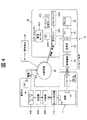
図4には、ショット処理装置の点検システム10の全体構成がブロック図にて示されている。図4に示されるように、パソコン(PC)24はプリンタ26の他にサポートセンター32の社内ネットワーク32Aに接続されている。サポートセンター32とは、ショット処理装置12が設置された現場を支援するための機関である。なお、パソコン24及びプリンタ26は、サポートセンター32に設置されてもよいし、サポートセンター32以外の場所に設置されてもよい。サポートセンター32では、社内ネットワーク32Aにメインサーバ32S及びパソコン32Bが接続されている。すなわち、サポートセンター32に設置されたメインサーバ32S及びパソコン32Bは、通信回線を介してパソコン24に接続されている。
FIG. 4 is a block diagram showing the overall configuration of the
パソコン32Bには、管理サーバ32C及び監視モニター32Dが通信回線を介して接続されている。なお、管理サーバ32Cは、社内ネットワーク32Aに直接接続されてもよい。管理サーバ32Cには点検等に関するデータがデータベースとして格納されている。社内ネットワーク32Aは、公衆回線34(通信回線ネットワーク)に接続されており、パソコン32Bは、社内ネットワーク32Aを介して公衆回線34に接続されている。また、公衆回線34には、管理サーバ32C等を管理する管理会社36のシステムが接続されると共に、パソコン38が接続されている。パソコン38は、ショット処理装置12のユーザである顧客先に設置されている。そして、サポートセンター32に設置されたパソコン32Bは、パソコン24から受信した点検結果の情報を、顧客先のパソコン38に社内ネットワーク32A及び公衆回線34(通信回線ネットワーク)を介して送信する。なお、図4では、サポートセンター32のパソコン32Bから顧客先のパソコン38への送信経路を二点鎖線で示している。以上により、点検結果の情報(パソコン24の出力情報)は、サポートセンター32のパソコン32Bで参照できると共に、パソコン32Bから社内ネットワーク32A及び公衆回線34を介して顧客先のパソコン38に提供可能となっている。
A management server 32C and a
また、図4の左側に示されるように、点検対象となるショット処理装置12の部品14の少なくともいずれか(特に重要なもの)にはセンサ付発信器42Aが取り付けられている。センサ付発信器42Aは、振動、騒音、及び温度を検知すると共に検知した検知情報を無線で送信できる発信器である。センサ付発信器42Aは、検知情報を中継器42Bを介して受信器(親器)42Cに送信可能となっている。換言すれば、受信器42Cは、センサ付発信器42Aから送信された検知情報を受信する。なお、センサ付発信器42Aと受信器42Cとの距離が短い場合、中継器42Bは不要である。
As shown on the left side of FIG. 4, a sensor-equipped
受信器42Cは、モバイルルータ(変換送信器)42Dに通信回線で接続されており、受信器42Cで受信した検知情報のデータはモバイルルータ42Dに転送される。モバイルルータ42Dは、受信器42Cで受信された検知情報を無線ネットワーク(図示省略)内の無線基地局42Eに送信するための通信機器である。また、無線基地局42Eは、公衆回線34(通信回線ネットワーク)に接続されている。そして、サポートセンター32に設置された管理サーバ32Cは、モバイルルータ42Dから無線基地局42E及び通信回線ネットワーク(公衆回線34及び社内ネットワーク32A)を介して検知情報を受信する。
The
センサ付発信器42Aは定期的に前述の検知情報を発信する。センサ付発信器42Aの検知情報は、サポートセンター32の管理サーバ32Cに格納される。これにより、管理サーバ32Cに格納された検知情報は、通信回線ネットワーク(公衆回線34及び社内ネットワーク32A)を介して顧客先のパソコン38からアクセス可能とされている。また、管理サーバ32Cに格納された検知情報は、サポートセンター32のパソコン32Bからもアクセス可能とされている。このため、顧客先のパソコン38(端末)及びサポートセンター32のパソコン32Bから検知情報を閲覧することができる。また、サポートセンター32では、センサ付発信器42Aの検知情報を収集分析し、部品交換時期の予想情報を顧客先(ユーザー)に提供すると共に、予防保全計画を提案する。
The sensor-equipped
(ショット処理装置の点検システムを用いた処理手順)
次に、ショット処理装置の点検システム10を用いた処理手順について図5のフローチャートを参照しながら説明する。(Processing procedure using an inspection system for shot processing equipment)
Next, a processing procedure using the
図5(A)に示されるように、装置点検時には、まず携帯端末20の電源を入れる(S1)。次に、携帯端末20で点検するショット処理装置12のバーコード12Bをスキャンする(S2)。すると、携帯端末20には、ショット処理装置12全体の点検対象となる部品14が列挙される形で表示される(S3)。次に、携帯端末20で点検対象となる部品14のバーコード18をスキャンする(S4)。なお、このスキャン処理(読み取り処理)の前に携帯端末20に種々の情報(例えば、点検作業者のIDコード、日常点検、週次点検、月次点検のいずれであるか等の情報)を入力する形態であってもよい。
As shown in FIG. 5A, at the time of checking the apparatus, the
スキャン処理を行なうと、携帯端末20には、バーコード18の識別用データに応じて点検画面が表示される。この点検画面には、点検項目が列挙される形で表示される。点検作業者は、携帯端末20の点検画面に従って(点検画面の表示に応じて)点検対象となる部品14における点検項目のバーコード18A、18Bをスキャンし、その点検項目の点検を行う(S5)。このとき、携帯端末20の点検画面には、点検項目及びその判定基準が表示されると共に、点検項目に対応する点検結果の入力(画面上の選択肢の選択等)が可能となる。そして、点検作業者は、判定基準に従った点検結果(例えば、○、×等の判定結果)を携帯端末20に入力する(S6)。なお、点検日がいつであるかの情報(データ)は、一例として携帯端末20のシステム日付が自動的に書き込まれる。
When the scanning process is performed, an inspection screen is displayed on the
次に、点検作業者は、未点検の項目が有るか否かを判断し(S7)、有る場合には、点検項目のバーコード18A、18Bをスキャンしその点検項目の点検を行う工程(S5)に戻る。また、未点検の項目がない場合には、点検作業者は、未点検の部品14が有るか否かを判断する(S8)。そして、点検作業者は、未点検の部品14が有る場合には、点検対象となる部品14のバーコード18のスキャンを行う工程(S4)に戻る。また、未点検の部品14がない場合には、点検作業者は、点検予定のショット処理装置12が有るか否かを判断し(S9)、有る場合には、点検するショット処理装置12のバーコード12Bをスキャンする工程(S2)に戻る。一方、点検予定のショット処理装置12がない場合、点検作業者は、点検を終了する。
Next, the inspection operator determines whether or not there is an uninspected item (S7). If there is, an inspection
このように、ショット処理装置の点検システム10によれば、ショット処理装置12の各点検箇所で該当部品の点検を確実に行わせることができる。
As described above, according to the
点検が終了したら、点検作業者は、図5(B)に示されるデータ転送時の処理を行う。図5(B)に示されるように、データ転送時には、まず、携帯端末20を送信器22にセットする(S11)。次に、パソコン24の電源を入れる(S12)、そして、パソコン24でデータ転送ソフトを立ち上げ(S13)、パソコン24を待受け状態にする。なお、この直後に後述する点検報告書作成ソフトを立ち上げてもよい。
When the inspection is completed, the inspection operator performs the data transfer process shown in FIG. As shown in FIG. 5B, at the time of data transfer, first, the
次に、携帯端末20の画面及び入力部20Cからの操作によって、携帯端末20のデータ(点検画面に応じて点検項目毎に入力された点検結果の情報)をパソコン24に転送(送信)する(S14)。そして、転送されたデータをパソコン24の記憶部24Dに保存する(S15)。その後、データ転送ソフトを終了する(S16)。なお、データ転送ソフトは、後述するパソコン24をOFFする直前に終了させてもよい。
Next, the data of the portable terminal 20 (information of the inspection result input for each inspection item according to the inspection screen) is transferred (transmitted) to the
図5(C)には、パソコン24に転送データを保存した後の処理フローが示されている。図5(C)に示されるように、この処理フローでは、まず、点検報告書をプリントアウトするか否かを作業者が判断する(S21)。プリントアウトしない場合はパソコン24の電源をOFFにし(S29)、処理を終了する。一方、プリントアウトする場合は、パソコン24上で点検報告書作成ソフトを立ち上げる(S22)。次に、点検報告書作成ソフトで点検データを取り込む(S23)。そして、点検をした装置のうち、プリントアウトしたい装置を選択し(S24)、点検日を入力すると(S25)、点検者、及び点検結果等が表示部24Eに表示され(S26)、印刷処理の操作を実行することでプリンタ26にプリントアウトされる(S27)。その後、点検報告書作成ソフトを終了させ(S28)、パソコン24の電源をOFFにして(S29)、処理を終了させる。
FIG. 5C shows a processing flow after the transfer data is stored in the
(遠心式投射機を備えたショットブラスト装置の点検) (Inspection of shot blasting equipment equipped with a centrifugal projector)
次に、図6を参照しながら、点検対象のショット処理装置がショットブラスト装置50である場合について説明する。図6には、ショットブラスト装置50が斜視図にて示されている。まず、このショットブラスト装置50について概説する。なお、このショットブラスト装置50には、装置識別用としてショットブラスト装置50の識別用データを表すバーコード(図示省略)が付されている。
Next, the case where the shot processing apparatus to be inspected is the shot
図6に示されるように、ショットブラスト装置50は、内部に投射材が投射される投射室52Aを有するキャビネット52を備えている。キャビネット52の天井部52Bには、投射部としての遠心式投射機54が取り付けられている。遠心式投射機54は、ハウジング54Aと、ハウジング54Aの側板に隣接して配置される駆動モータ54Bと、ハウジング54Aの内側に配置されて駆動モータ54Bの駆動軸に連結される羽根車(インペラ)54Cと、を備えている。駆動モータ54Bの電流値は、図示しない電流計によって測定可能となっている。また、羽根車54Cには、その回転軸の外周に複数の羽根板(ブレード)54C1が設けられている。そして、遠心式投射機54は、駆動モータ54Bの駆動力で羽根車54Cを高速回転させることで投射材に遠心力を付与して投射材を投射室52A内の被処理対象物へ向けて投射するようになっている。
As shown in FIG. 6, the
また、ショットブラスト装置50は、遠心式投射機54に投射材を供給するタンク56を備えている。タンク56の下部は、導入管58等を介して遠心式投射機54に接続されている。また、タンク56の上部は、セパレータ60を介してバケットエレベータ62の上部に接続されている。バケットエレベータ62は、装置上下方向を長手方向として配置され、遠心式投射機54から投射された投射材をタンク56へ戻す循環路に設けられている。なお、循環路は、セパレータ60、バケットエレベータ62、及び、キャビネット52に設けられて投射室52Aの下方側に配置されたホッパ64を含む構成部にて形成されている。また、ホッパ64の排出口は、バケットエレベータ62の下部収集口に臨む位置に配置されている。
Further, the
バケットエレベータ62は、ショットブラスト装置50の上部及び下部に配置されたプーリ62A(図中では上側のみ図示)に無端ベルト62Bが巻き掛けられると共に、無端ベルト62Bに多数のバケット62Cが取り付けられている。なお、図中では、バケットエレベータ62の上部のみを隠れ線(点線)で示している。また、図を見やすくするために、図中では、多数のバケット62Cのうちの二つのバケット62Cのみを図示しているが、実際には多数のバケット62Cが無端ベルト62Bの周方向に隣接して配置されている。また、上側のプーリ62Aは、モータ(図示省略)に接続されて回転駆動可能とされている。これにより、バケットエレベータ62は、ホッパ64で回収した投射材をバケット62Cで掬い上げると共に、上側のプーリ62Aを前記モータで回転させることによって、バケット62C内の投射材を上方側へ向けて搬送するようになっている。
In the
なお、バケットエレベータ62に代えて、スクリュコンベア、ベルトコンベア、オシレートコンベア、空気輸送等の搬送方式が適用されてもよい。
In place of the
また、バケットエレベータ62の上部と連通するセパレータ60は、ダクト66を介して集塵機68と接続されている。そして、セパレータ60は、集塵機68の吸引力によって生じる気流を利用して、バケットエレベータ62から流入された投射材を含む粉粒物を、軽量物と重量物とに選別し、投射材から異物を分級するようになっている。また、セパレータ60は、再利用可能な投射材を前述したタンク56に落とし込む位置に設定されている。なお、セパレータ60としては、サイクロン、セトリングチャンバー、ロータリスクリーン、振動篩等が適用可能である。
The
集塵機68の内部には、空気を吸入するファン(図示省略)が設けられている。これにより、集塵機68は、バケットエレベータ62、セパレータ60、及びダクト66を介して、キャビネット52の内部の粉塵を含む空気を吸引する。また、集塵機68の内部において前記ファンよりも流路上流側の空間には、当該空間を流路上流側と流路下流側とに仕切るように濾布が張られている。前記濾布は、粉塵の捕捉用とされている。集塵機68は、前記濾布が設けられることで、清浄空気を排出するようになっている。また、集塵機68には、吸気側と排気側との差圧を測定する差圧計(図示省略)が設けられている。
Inside the
次に、ショットブラスト装置50の点検について説明する。
Next, inspection of the
前述した遠心式投射機54は、ショットブラスト装置50において予め設定された点検対象となる部品となっており、遠心式投射機54には、遠心式投射機54の識別用データを表すバーコード(図示省略)が付されている。図1に示される携帯端末20は、バーコードリーダ20Aが読み取ったバーコード18が図6に示される遠心式投射機54を表す識別用データである場合に、表示部20E(図1参照)が点検画面に駆動モータ54Bの電流値及び遠心式投射機54の振動を点検項目として表示する。
The centrifugal projector 54 described above is a part to be inspected in advance set in the
駆動モータ54Bの電流値は、ショットブラスト装置50を作動させて電流計を目視で読み取ることで確認される。点検作業者は、駆動モータ54Bの電流値が予め想定した電流値の正常範囲内にある場合は、異常なし(○)の判定をする。一方、駆動モータ54Bの電流値が正常範囲内になく注意すべき範囲内にある場合、点検作業者は注意(△)の判定をする。さらに、駆動モータ54Bの電流値が正常範囲内になくかつ注意すべき範囲内にもない場合、点検作業者は異常あり(×)の判定をする。なお、注意(△)の状態は、調整又は部品準備が必要な状態であり、異常あり(×)の状態は、修理や部品交換が必要な状態である(以下の説明における注意(△)及び異常あり(×)も同様)。ここでの判定結果(点検結果)は、点検作業者により携帯端末20(図1参照)に入力される。
The current value of the
また、遠心式投射機54の振動は、遠心式投射機54の摩耗を点検させるための点検項目であり、ショットブラスト装置50を作動させた後に目視することで確認される。点検作業者は、遠心式投射機54の振動の程度が予め想定した正常範囲内にある場合は、異常なし(○)の判定をする。一方、遠心式投射機54の振動の程度が正常範囲内になく注意すべき範囲内にある場合、点検作業者は注意(△)の判定をする。さらに、遠心式投射機54の振動の程度が正常範囲内になくかつ注意すべき範囲内にもない場合、点検作業者は異常あり(×)の判定をする。ここでの判定結果(点検結果)も、点検作業者により携帯端末20(図1参照)に入力される。
The vibration of the centrifugal projector 54 is an inspection item for checking the wear of the centrifugal projector 54 and is confirmed by visual inspection after the
ここで、駆動モータ54Bの電流値を点検することで投射量が適切であるか否かを確認することができる。また、遠心式投射機54の振動を点検することで羽根車54Cの羽根板54C1の摩耗状態を確認することができる。また、羽根車54Cを回転自在に支持する軸受(図示省略)の損傷なども確認できる。そして、これらの点検項目に対応した保守がなされることで、遠心式投射機54が適切に投射材を投射することができる。
Here, it is possible to confirm whether or not the projection amount is appropriate by checking the current value of the
また、バケットエレベータ62も、ショットブラスト装置50において予め設定された点検対象となる部品となっており、バケットエレベータ62には、バケットエレベータ62の識別用データを表すバーコード(図示省略)が付されている。図1に示される携帯端末20は、バーコードリーダ20Aが読み取ったバーコード18が図6に示されるバケットエレベータ62を表す識別用データである場合に表示部20E(図1参照)が点検画面にバケットエレベータ62の作動時の異音を点検項目として表示する。
Further, the
バケットエレベータ62の作動時の異音は、ショットブラスト装置50を作動させた後に聴音で確認される。点検作業者は、バケットエレベータ62の作動時の異音の程度が予め想定した正常範囲内にある場合は、異常なし(○)の判定をする。一方、バケットエレベータ62の作動時の異音の程度が正常範囲内になく注意すべき範囲内にある場合、点検作業者は注意(△)の判定をする。さらに、バケットエレベータ62の作動時の異音の程度が正常範囲内になくかつ注意すべき範囲内にもない場合、点検作業者は異常あり(×)の判定をする。ここでの判定結果(点検結果)も、点検作業者により携帯端末20(図1参照)に入力される。
Abnormal noise during operation of the
ここで、バケットエレベータ62の作動時の異音が点検されることで、バケットエレベータ62の蛇行やベルトテンションが適正か否かを確認することができる。そして、この点検項目に対応した保守がなされることで、バケットエレベータ62を良好に作動させることができる。
Here, it is possible to check whether or not the meandering of the
また、キャビネット52も、ショットブラスト装置50において予め設定された点検対象となる部品となっており、キャビネット52には、キャビネット52の識別用データを表すバーコード(図示省略)が付されている。図1に示される携帯端末20は、バーコードリーダ20Aが読み取ったバーコード18が図6に示されるキャビネット52を表す識別用データである場合に表示部20E(図1参照)が点検画面にキャビネット52からの投射材の漏れを点検項目として表示する。
The cabinet 52 is also a part to be inspected in advance set in the
キャビネット52からの投射材の漏れは、ショットブラスト装置50を作動させた後に目視で確認される。点検作業者は、キャビネット52からの投射材の漏れの程度が予め想定した正常範囲内にある場合は、異常なし(○)の判定をする。一方、キャビネット52からの投射材の漏れの程度が正常範囲内になく注意すべき範囲内にある場合、点検作業者は注意(△)の判定をする。さらに、キャビネット52からの投射材の漏れの程度が正常範囲内になくかつ注意すべき範囲内にもない場合、点検作業者は異常あり(×)の判定をする。ここでの判定結果(点検結果)も、点検作業者により携帯端末20(図1参照)に入力される。
The leakage of the projection material from the cabinet 52 is visually confirmed after the
ここで、キャビネット52からの投射材の漏れが点検されることで、キャビネット52のシール状態を確認することができる。そして、この点検項目に対応した保守がなされることで、キャビネット52のシール性が確保されてキャビネット52からの投射材の漏れが抑えられる。 Here, by checking the leakage of the projection material from the cabinet 52, the sealing state of the cabinet 52 can be confirmed. And the maintenance corresponding to this inspection item is performed, the sealing property of the cabinet 52 is ensured, and the leakage of the projection material from the cabinet 52 is suppressed.
さらに、本実施形態では、集塵機68も、ショットブラスト装置50において予め設定された点検対象となる部品となっており、集塵機68には、集塵機68の識別用データを表すバーコード(図示省略)が付されている。図1に示される携帯端末20は、バーコードリーダ20Aが読み取ったバーコード18が図6に示される集塵機68を表す識別用データである場合に、表示部20E(図1参照)が点検画面に集塵機68の作動時の異音、集塵機68の吸気側と排気側との差圧、及び集塵機68からの粉塵(ダスト)漏れを点検項目として表示する。
Further, in the present embodiment, the
集塵機68の作動時の異音は、ショットブラスト装置50を作動させた後に聴音で確認される。点検作業者は、集塵機68の作動時の異音の程度が予め想定した正常範囲内にある場合は、異常なし(○)の判定をする。一方、集塵機68の作動時の異音の程度が正常範囲内になく注意すべき範囲内にある場合、点検作業者は注意(△)の判定をする。さらに、集塵機68の作動時の異音の程度が正常範囲内になくかつ注意すべき範囲内にもない場合、点検作業者は異常あり(×)の判定をする。ここでの判定結果(点検結果)も、点検作業者により携帯端末20(図1参照)に入力される。
Abnormal noise during operation of the
また、集塵機68の吸気側と排気側との差圧は、ショットブラスト装置50を作動させた後に、集塵機68の吸気側と排気側との差圧を測定する差圧計を目視で読み取ることで確認される。点検作業者は、差圧計の値が予め想定した正常範囲内にある場合は、異常なし(○)の判定をする。一方、差圧計の値が正常範囲内になく注意すべき範囲内にある場合、点検作業者は注意(△)の判定をする。さらに、差圧計の値が正常範囲内になくかつ注意すべき範囲内にもない場合、点検作業者は異常あり(×)の判定をする。ここでの判定結果(点検結果)も、点検作業者により携帯端末20(図1参照)に入力される。
The differential pressure between the intake side and the exhaust side of the
また、集塵機68からの粉塵漏れは、ショットブラスト装置50を作動させた後に、目視で確認される。点検作業者は、集塵機68からの粉塵漏れの程度が予め想定した正常範囲内にある場合は、異常なし(○)の判定をする。一方、集塵機68からの粉塵漏れの程度が正常範囲内になく注意すべき範囲内にある場合、点検作業者は注意(△)の判定をする。さらに、集塵機68からの粉塵漏れの程度が正常範囲内になくかつ注意すべき範囲内にもない場合、点検作業者は異常あり(×)の判定をする。ここでの判定結果(点検結果)も、点検作業者により携帯端末20(図1参照)に入力される。
Further, dust leakage from the
ここで、集塵機68の作動時の異音、集塵機68の吸気側と排気側との差圧、及び集塵機68からの粉塵漏れが点検されることで、集塵機68のファンや軸受けの摩耗、濾布の破れ及び目詰まりの有無を確認することができる。そして、これらの点検項目に対応した保守がなされることで、集塵機68を良好に作動させることができる。
Here, abnormal noise during operation of the
以上説明したショットブラスト装置50には、点検対象となる部品における点検項目の識別用データを表すバーコード(図示省略、図1の符号18A、18B参照、点検項目識別部)が設けられている。詳細説明を省略するが、これらのバーコードは、点検項目に対応する点検対象となる部品又はその周囲部に設けられている。すなわち、ショットブラスト装置50において、点検項目の識別用データを表すバーコードは、前記の「ショット処理装置の点検システムの概要」及び「ショット処理装置の点検システムを用いた処理手順」で説明したバーコード18A、18B(図1参照)に対応する構成部である。このように、点検項目の識別用データを表すバーコードが設けられることで、点検項目毎に当該バーコードを図1に示される携帯端末20のバーコードリーダ20Aで読み取ってから点検結果が入力されることになるので、点検の堅実化をサポートすることができる。
The
以上のように、ショット処理装置の点検システム10では、図6に示されるショットブラスト装置50の各点検箇所で該当部品の点検を確実に行わせることができ、投射材を用いることに起因したショットブラスト装置50の保守点検に資することができる。
As described above, in the
(エア圧式投射機を備えたショットピーニング装置の点検)
次に、図7を参照しながら、点検対象のショット処理装置がショットピーニング装置70である場合について説明する。図7には、ショットピーニング装置70が概略構成図にて示されている。まず、このショットピーニング装置70について概説する。なお、このショットピーニング装置70には、装置識別用としてショットピーニング装置70の識別用データを表すバーコード(図示省略)が付されている。(Inspection of shot peening equipment equipped with air pressure projector)
Next, the case where the shot processing apparatus to be inspected is the
図7に示されるように、ショットピーニング装置70は、装置本体70Aを備えている。また、装置本体70Aは、内部に投射材が投射される投射室72Aを有するキャビネット72を備えている。キャビネット72の側壁部には、エア圧式投射機74の投射部としてのノズル76が取り付けられている。
As shown in FIG. 7, the
エア圧式投射機74は、被処理対象物Wに投射材を噴射(投射)するためのものであり、ノズル76と、エア供給部としてのコンプレッサ80と、加圧タンク82と、を含んで構成されている。コンプレッサ80は、加圧されたエアを供給することが可能な圧縮空気供給装置である。また、加圧タンク82は、投射材を貯蔵すると共に下部側から投射材を供給するためのタンクである。加圧タンク82の下部(底部)には、カットゲート(図示省略)が設けられたショット流出口82Bが形成されており、このショット流出口82Bには、タンク接続配管部79Aの一端部が接続されている。このタンク接続配管部79Aを介して加圧タンク82の下部側にはミキシング部79Bが連通しており、ミキシング部79Bは、投射材とエアとを混合させる空間を形成している。また、タンク接続配管部79Aの流路中間部には、ショット流量制御弁(図示省略)が設けられている。
The air
加圧タンク82及びミキシング部79Bは、エア供給配管部78によってコンプレッサ80に連通している。エア供給配管部78は、一端部がコンプレッサ80に接続されると共に、流路中間部で分岐しており、分岐した一方の端部が加圧タンク82の側部のエア流入口82Aに接続され、分岐した他方の端部がミキシング部79Bに接続されている。すなわち、エア供給配管部78は、加圧タンク82内の加圧用としてコンプレッサ80と加圧タンク82とを連通させる第一エア供給配管部78Aと、コンプレッサ80とミキシング部79Bとを連通させる第二エア供給配管部78Bと、備えている。なお、エア供給配管部78において分岐点よりも流路上流側の構成部は、第一エア供給配管部78Aと第二エア供給配管部78Bとを兼用する兼用配管部78Xとなっている。
The
第一エア供給配管部78Aにおいて兼用配管部78Xよりも流路下流側の配管部には、第一エア流量制御弁(図示省略)が設けられており、この第一エア流量制御弁が開かれることで、コンプレッサ80からの圧縮空気が加圧タンク82内に供給される。これにより、加圧タンク82内は加圧可能となっている。
In the first air
また、第二エア供給配管部78Bにおいて兼用配管部78Xよりも流路下流側の配管部には、第二エア流量制御弁(図示省略)が設けられている。すなわち、加圧タンク82内が加圧された状態で前記カットゲート及び前記ショット流量制御弁が開かれかつ第二エア流量制御弁が開かれた場合、加圧タンク82から供給された投射材と、コンプレッサ80から供給された圧縮空気とが、ミキシング部79Bにて混合されるようになっている。
In the second air
ミキシング部79Bには輸送配管部79Cの一端部が接続されている。この輸送配管部79Cの他端部は噴射用(ショットピーニング用)のノズル76に接続されている。すなわち、ミキシング部79Bとノズル76とは、輸送配管部79Cによって連通されている。そして、輸送配管部79Cは、ミキシング部79Bからノズル76へエア及び投射材を輸送するための配管部とされている。これにより、ミキシング部79Bに流れた投射材は、圧縮空気と混合された状態でノズル76の先端部より噴射されるようになっている。換言すれば、エア圧式投射機74は、コンプレッサ80で加圧されて第二エア供給配管部78Bを流通させたエアと加圧タンク82から供給された投射材とをミキシング部79Bで混合させてノズル76から噴射する。
One end of a transport piping part 79C is connected to the mixing
また、第一エア供給配管部78Aにおいて、兼用配管部78Xには、圧力計84が設置されている。圧力計84は、第一エア供給配管部78A(兼用配管部78X)におけるエアの圧力の測定用とされている。
Further, in the first air
ショットピーニング装置70は、エア圧式投射機74に投射材を供給するタンク86を備えている。タンク86は、エア圧式投射機74における加圧タンク82の上方側に配置され、導入管88を介して加圧タンク82に接続されている。導入管88には、流量調整弁90が設けられている。
The
また、ショットピーニング装置70には、エア圧式投射機74から投射された投射材をタンク86へ戻す循環路が設けられ、前記循環路には、前述したショットブラスト装置50のバケットエレベータ62(図6参照)と同様の構成を備えたバケットエレベータ92が設けられている。すなわち、バケットエレベータ92は、上下に配置されたプーリ92Aに無端ベルト92Bが巻き掛けられると共に、無端ベルト92Bに多数のバケット92Cが取り付けられている。なお、バケットエレベータ92に代えて、スクリュコンベア、ベルトコンベア、オシレートコンベア、空気輸送等の搬送方式が適用されてもよい。また、本実施形態では、循環路は、導入管88、タンク86、バケットエレベータ92、及び、キャビネット72に設けられて投射室72Aの下方側に配置されたホッパ94を含む構成部にて形成されている。バケットエレベータ92は、ホッパ94で回収された投射材を受け入れて当該投射材を上方側へ搬送するようになっており、搬送した投射材をタンク86に供給するようになっている。
Further, the
また、ショットピーニング装置70には、前述したショットブラスト装置50の集塵機68(図6参照)と同様の構成を備えた集塵機98が設けられている。集塵機98は、ダクト96を介してキャビネット72に接続されており、キャビネット72の内部の粉塵を含む空気を吸引するようになっている。
The
次に、ショットピーニング装置70の点検について説明する。
Next, inspection of the
前述した第一エア供給配管部78Aは、ショットピーニング装置70において予め設定された点検対象となる部品となっており、第一エア供給配管部78Aの周囲部には、第一エア供給配管部78Aの識別用データを表すバーコード(図示省略)が付されている。図1に示される携帯端末20は、バーコードリーダ20Aが読み取ったバーコード18が図7に示される第一エア供給配管部78Aを表す識別用データである場合に、表示部20E(図1参照)が点検画面に第一エア供給配管部78Aにおけるエアの圧力値を点検項目として表示する。
The first air
第一エア供給配管部78Aにおけるエアの圧力値は、エア圧式投射機74を作動させて圧力計84を目視で読み取ることで確認される。点検作業者は、第一エア供給配管部78Aにおけるエアの圧力値が予め想定した正常値である場合は、異常なし(○)の判定をする。一方、第一エア供給配管部78Aにおけるエアの圧力値が正常値でなく注意すべき範囲内にある場合、点検作業者は注意(△)の判定をする。さらに、第一エア供給配管部78Aにおけるエアの圧力値が正常値でなく注意すべき範囲内にもない場合、点検作業者は異常あり(×)の判定をする。ここでの判定結果(点検結果)は、点検作業者により携帯端末20(図1参照)に入力される。
The pressure value of air in the first air
ここで、加圧タンク82内の加圧用として設けられた第一エア供給配管部78Aのエアの圧力値が点検されることで、適切な投射条件で投射が行われるか否かを確認することができる。そして、この点検項目に対応した保守がなされることで、エア圧式投射機が適切に投射材を投射することができる。
Here, by checking the air pressure value of the first air
また、ノズル76は、ショットピーニング装置70において予め設定された点検対象となる部品となっており、ノズル76の周囲部には、ノズル76の識別用データを表すバーコード(図示省略)が付されている。図1に示される携帯端末20は、バーコードリーダ20Aが読み取ったバーコード18が図7に示されるノズル76を表す識別用データである場合に、表示部20E(図1参照)が点検画面にノズル76の摩耗を点検項目として表示する。
The
ノズル76の摩耗は、エア圧式投射機74を作動させずに点検され、目視で確認される。点検作業者は、ノズル76の摩耗の程度が予め想定した正常範囲内にある場合は、異常なし(○)の判定をする。一方、ノズル76の摩耗の程度が正常範囲内になく注意すべき範囲内にある場合、点検作業者は注意(△)の判定をする。さらに、ノズル76の摩耗の程度が正常範囲内になくかつ注意すべき範囲内にもない場合、点検作業者は異常あり(×)の判定をする。ここでの判定結果(点検結果)も、点検作業者により携帯端末20(図1参照)に入力される。ここで、ノズル76の摩耗が点検されて保守されることで、投射範囲の広がり及び投射圧力の低下が抑えられる。
The wear of the
また、バケットエレベータ92も、ショットピーニング装置70において予め設定された点検対象となる部品となっており、バケットエレベータ92には、バケットエレベータ92の識別用データを表すバーコード(図示省略)が付されている。図1に示される携帯端末20は、バーコードリーダ20Aが読み取ったバーコード18が図7に示されるバケットエレベータ92を表す識別用データである場合に表示部20E(図1参照)が点検画面にバケットエレベータ92の作動時の異音を点検項目として表示する。
Further, the
バケットエレベータ92の作動時の異音は、ショットピーニング装置70を作動させた後に聴音で確認される。点検作業者は、バケットエレベータ92の作動時の異音の程度が予め想定した正常範囲内にある場合は、異常なし(○)の判定をする。一方、バケットエレベータ92の作動時の異音の程度が正常範囲内になく注意すべき範囲内にある場合、点検作業者は注意(△)の判定をする。さらに、バケットエレベータ92の作動時の異音の程度が正常範囲内になくかつ注意すべき範囲内にもない場合、点検作業者は異常あり(×)の判定をする。ここでの判定結果(点検結果)も、点検作業者により携帯端末20(図1参照)に入力される。
Abnormal noise during operation of the
ここで、バケットエレベータ92の作動時の異音が点検されることで、バケットエレベータ92の蛇行やベルトテンションが適正か否かを確認することができる。そして、この点検項目に対応した保守がなされることで、バケットエレベータ92を良好に作動させることができる。
Here, it is possible to check whether or not the meandering of the
また、キャビネット72も、ショットピーニング装置70において予め設定された点検対象となる部品となっており、キャビネット72には、キャビネット72の識別用データを表すバーコード(図示省略)が付されている。図1に示される携帯端末20は、バーコードリーダ20Aが読み取ったバーコード18が図7に示されるキャビネット72を表す識別用データである場合に表示部20E(図1参照)が点検画面にキャビネット72からの投射材の漏れを点検項目として表示する。
The
キャビネット72からの投射材の漏れは、ショットピーニング装置70を作動させた後に目視で確認される。点検作業者は、キャビネット72からの投射材の漏れの程度が予め想定した正常範囲内にある場合は、異常なし(○)の判定をする。一方、キャビネット72からの投射材の漏れの程度が正常範囲内になく注意すべき範囲内にある場合、点検作業者は注意(△)の判定をする。さらに、キャビネット72からの投射材の漏れの程度が正常範囲内になくかつ注意すべき範囲内にもない場合、点検作業者は異常あり(×)の判定をする。ここでの判定結果(点検結果)も、点検作業者により携帯端末20(図1参照)に入力される。
The leakage of the projection material from the
ここで、キャビネット72からの投射材の漏れが点検されることで、キャビネット72のシール状態を確認することができる。そして、この点検項目に対応した保守がなされることで、キャビネット72のシール性が確保されてキャビネット72からの投射材の漏れが抑えられる。
Here, by checking the leakage of the projection material from the
さらに、集塵機98も、ショットピーニング装置70において予め設定された点検対象となる部品となっており、集塵機98には、集塵機98の識別用データを表すバーコード(図示省略)が付されている。図1に示される携帯端末20は、バーコードリーダ20Aが読み取ったバーコード18が図7に示される集塵機98を表す識別用データである場合に、表示部20E(図1参照)が点検画面に集塵機98の作動時の異音、集塵機98の吸気側と排気側との差圧、及び集塵機98からの粉塵(ダスト)漏れを点検項目として表示する。
Further, the
集塵機98の作動時の異音は、ショットピーニング装置70を作動させた後に聴音で確認される。点検作業者は、集塵機98の作動時の異音の程度が予め想定した正常範囲内にある場合は、異常なし(○)の判定をする。一方、集塵機98の作動時の異音の程度が正常範囲内になく注意すべき範囲内にある場合、点検作業者は注意(△)の判定をする。さらに、集塵機98の作動時の異音の程度が正常範囲内になくかつ注意すべき範囲内にもない場合、点検作業者は異常あり(×)の判定をする。ここでの判定結果(点検結果)も、点検作業者により携帯端末20(図1参照)に入力される。
Abnormal noise during operation of the
また、集塵機98の吸気側と排気側との差圧は、ショットピーニング装置70を作動させた後に、集塵機98の吸気側と排気側との差圧を測定する差圧計(図示省略)を目視で読み取ることで確認される。点検作業者は、差圧計の値が予め想定した正常範囲内にある場合は、異常なし(○)の判定をする。一方、差圧計の値が正常範囲内になく注意すべき範囲内にある場合、点検作業者は注意(△)の判定をする。さらに、差圧計の値が正常範囲内になくかつ注意すべき範囲内にもない場合、点検作業者は異常あり(×)の判定をする。ここでの判定結果(点検結果)も、点検作業者により携帯端末20(図1参照)に入力される。
In addition, the differential pressure between the intake side and the exhaust side of the
また、集塵機98からの粉塵漏れは、ショットピーニング装置70を作動させた後に、目視で確認される。点検作業者は、集塵機98からの粉塵漏れの程度が予め想定した正常範囲内にある場合は、異常なし(○)の判定をする。一方、集塵機98からの粉塵漏れの程度が正常範囲内になく注意すべき範囲内にある場合、点検作業者は注意(△)の判定をする。さらに、集塵機98からの粉塵漏れの程度が正常範囲内になくかつ注意すべき範囲内にもない場合、点検作業者は異常あり(×)の判定をする。ここでの判定結果(点検結果)も、点検作業者により携帯端末20(図1参照)に入力される。
In addition, dust leakage from the
ここで、集塵機98の作動時の異音、集塵機98の吸気側と排気側との差圧、及び集塵機98からの粉塵漏れが点検されることで、集塵機98のファンや軸受けの摩耗、濾布の破れ及び目詰まりの有無を確認することができる。そして、これらの点検項目に対応した保守がなされることで、集塵機98を良好に作動させることができる。
Here, abnormal noise during operation of the
以上説明したショットピーニング装置70には、点検対象となる部品における点検項目の識別用データを表すバーコード(図示省略、図1の符号18A、18B参照、点検項目識別部)が設けられている。詳細説明を省略するが、これらのバーコードは、点検項目に対応する点検対象となる部品又はその周囲部に設けられている。すなわち、ショットピーニング装置70において、点検項目の識別用データを表すバーコードは、前記の「ショット処理装置の点検システムの概要」及び「ショット処理装置の点検システムを用いた処理手順」で説明したバーコード18A、18B(図1参照)に対応する構成部である。このように、点検項目の識別用データを表すバーコードが設けられることで、点検項目毎に当該バーコードを図1に示される携帯端末20のバーコードリーダ20Aで読み取ってから点検結果が入力されることになるので、点検の堅実化をサポートすることができる。
The
以上のように、ショット処理装置の点検システム10では、図7に示されるショットピーニング装置70の各点検箇所で該当部品の点検を確実に行わせることができ、投射材を用いることに起因したショットピーニング装置70の保守点検に資することができる。
As described above, in the
[第2の実施形態]
次に、本発明の第2の実施形態に係るショット処理装置の点検システムについて、第1の実施形態を示す図面を援用しながら説明する。なお、第2の実施形態は、以下に説明する点を除き、第1の実施形態と同様の構成とされている。よって、第1の実施形態と同様の構成部については説明を省略する。[Second Embodiment]
Next, an inspection system for a shot processing apparatus according to the second embodiment of the present invention will be described with reference to the drawings illustrating the first embodiment. The second embodiment has the same configuration as the first embodiment except for the points described below. Therefore, description of the same components as those in the first embodiment is omitted.
第2の実施形態では、図1に示される点検対象となる部品14の識別用データを表すバーコード18(部品識別部)が設けられていない。一方、点検対象となる部品14における点検項目の識別用データを表すバーコード18A、18B(点検項目識別部)は、ショット処理装置12において予め設定された点検対象となる部品14又はその周囲部に設けられている。
In the second embodiment, the barcode 18 (component identification unit) that represents the identification data of the
第2の実施形態では、図3に示される制御部20Bは、バーコードリーダ20Aから取得したショット処理装置12(図1参照)の識別用データ(バーコード12Bのデータ)をキーとして、記憶部20Dの点検項目テーブル及び判定基準テーブルを参照する。そして、制御部20Bは、参照した点検項目及び判定基準のデータを所定の表示形式に従って表示部20Eに表示させる。以上により、表示部20Eは、バーコードリーダ20Aが読み取ったバーコード12Bの識別用データに応じて点検項目等を表示するようになっている。
In the second embodiment, the
この第2の実施形態におけるショット処理装置の点検システムを用いた処理手順は、図5(A)に示される第1の実施形態における処理手順とは以下の点で異なっている。まず、図5(A)に示される「携帯端末に装置全体の点検部品が表示される工程」(S3)に代えて、「携帯端末に装置全体の点検項目が表示される工程」が適用される。また、図5(A)に示される「携帯端末で点検部品のバーコードをスキャンする工程」(S4)及び「未点検の部品の有無を判断する工程」(S8)は適用されない。 The processing procedure using the inspection system for a shot processing apparatus in the second embodiment differs from the processing procedure in the first embodiment shown in FIG. 5A in the following points. First, instead of “the step of displaying the inspection parts of the entire device on the portable terminal” (S3) shown in FIG. 5A, the “step of displaying the inspection items of the entire device on the portable terminal” is applied. The Further, the “step of scanning the barcode of the inspection part with the portable terminal” (S4) and the “step of determining whether there is an uninspected part” (S8) shown in FIG. 5A are not applied.
以上説明した第2の実施形態によっても、ショット処理装置の各点検箇所で該当部品の点検を確実に行わせることができ、投射材を用いることに起因したショット処理装置の保守点検に資することができる。 Also according to the second embodiment described above, it is possible to surely inspect the corresponding parts at each inspection point of the shot processing apparatus, which contributes to the maintenance inspection of the shot processing apparatus due to the use of the projection material. it can.
(実施形態の補足説明)
なお、上記実施形態において、点検時に目視で判定しているものについては、点検箇所を撮影し、撮影された画像のデータを併用して種々の判定をしてもよい。(Supplementary explanation of the embodiment)
In addition, in the said embodiment, about what is determined visually at the time of an inspection, an inspection location may be image | photographed and various determination may be carried out using the data of the image | photographed image together.
また、上記第1の実施形態では、図1に示されるように、部品識別部がバーコード18とされているが、部品識別部は、例えば、数字を含む文字、模様等のようなバーコード以外の他の部品識別部であってもよい。また、同様に、上記実施形態では、点検項目識別部がバーコード18A、18Bとされているが、点検項目識別部は、例えば、数字を含む文字、模様等のようなバーコード以外の他の点検項目識別部であってもよい。さらに、ショット処理装置の識別用データを表す装置識別部についても同様である。
In the first embodiment, as shown in FIG. 1, the component identification unit is a
また、上記実施形態では、コンピュータが図2に示されるパソコン24である場合を例に挙げて説明したが、コンピュータは、大型コンピュータであってもよい。同様に、図4に示されるパソコン32B、38に代えて、大型コンピュータが適用されてもよい。
In the above embodiment, the case where the computer is the
また、上記実施形態では、点検画面に応じて三段階評価による点検結果の情報が入力されているが、点検画面に応じて二段階評価又は五段階評価等のような三段階評価以外の多段階評価による点検結果の情報が入力されるように構成されてもよい。 In the above-described embodiment, information on the inspection result by the three-stage evaluation is input according to the inspection screen, but the multi-stage other than the three-stage evaluation such as the two-stage evaluation or the five-stage evaluation according to the inspection screen. It may be configured such that information of inspection results by evaluation is input.
また、点検対象となるショット処理装置は、遠心式投射機を備えたショットピーニング装置、遠心式投射機を備えたショットブラスト兼ショットピーニング装置、エア圧式投射機を備えたショットブラスト装置、及びエア圧式投射機を備えたショットブラスト兼ショットピーニング装置等でもよい。 Further, the shot processing device to be inspected is a shot peening device equipped with a centrifugal projector, a shot blast / shot peening device equipped with a centrifugal projector, a shot blast device equipped with an air pressure projector, and an air pressure type A shot blast and shot peening apparatus equipped with a projector may be used.
また、上記第1の実施形態の変形例として、点検項目識別部としてのバーコードが設けられない構成も採り得る。この変形例に係るショット処理装置の点検システムでは、図3に示される制御部20Bは、バーコードリーダ20Aから取得した部品14(図1参照)の識別用データ(バーコード18のデータ)をキーとして、記憶部20Dの点検項目テーブル及び判定基準テーブルを参照する。そして、制御部20Bは、参照した点検項目及び判定基準のデータを所定の表示形式に従って表示部20Eに表示させる。また、この変形例に係るショット処理装置の点検システムを用いた処理手順は、図5(A)の第1の実施形態における処理手順に示される「携帯端末の画面に従い点検項目のバーコードをスキャンし、点検を行う工程」(S5)に代えて、「携帯端末の画面に従い点検を行う工程」が適用されることになる。
In addition, as a modification of the first embodiment, a configuration in which a barcode as an inspection item identification unit is not provided may be employed. In the inspection system for a shot processing apparatus according to this modification, the
また、上記実施形態の変形例として、センサ付発信器(図4参照)は、部品の振動、騒音、及び温度のいずれか二つを検知すると共に検知した検知情報を無線で送信するものであってもよい。また、他の変形例として、センサ付発信器は、部品の振動、騒音、及び温度のいずれか一つを検知すると共に検知した検知情報を無線で送信するものであってもよい。 As a modification of the above embodiment, the sensor-equipped transmitter (see FIG. 4) detects any two of vibration, noise, and temperature of the component and transmits the detected detection information wirelessly. May be. As another modification, the transmitter with a sensor may detect any one of vibration, noise, and temperature of the component and transmit the detected detection information wirelessly.
また、上記実施形態の変形例として、図4に示されるセンサ付発信器42A、受信器42C、及びモバイルルータ42Dが設置されないような構成も採り得る。
As a modification of the above embodiment, a configuration in which the sensor-equipped
また、第2の実施形態の変形例として、図7に示される兼用配管部78Xに設置された圧力計84に代えて、第一エア供給配管部78Aにおいて兼用配管部78Xよりも流路下流側の配管部に圧力計を設置してもよい。また、他の変形例として、第一エア供給配管部78Aと第二エア供給配管部78Bとの兼用配管部78Xが設けられず、第一エア供給配管部と第二エア供給配管部とが別個独立に設置されてもよい。
Further, as a modification of the second embodiment, in place of the pressure gauge 84 installed in the dual-purpose piping part 78X shown in FIG. You may install a pressure gauge in the piping part. Further, as another modification, the first air
なお、上記実施形態及び上述の複数の変形例は、適宜組み合わされて実施可能である。 In addition, the said embodiment and the above-mentioned some modification can be implemented combining suitably.
以上、本発明の一例について説明したが、本発明は、上記に限定されるものでなく、上記以外にも、その主旨を逸脱しない範囲内において種々変形して実施可能であることは勿論である。 Although an example of the present invention has been described above, the present invention is not limited to the above, and it is needless to say that various modifications can be made without departing from the spirit of the present invention. .
以下に本明細書及び図面で用いた主な符号をまとめて示す。
10 ショット処理装置の点検システム
12 ショット処理装置
14 部品
18 バーコード(部品識別部)
18A、18B バーコード(点検項目識別部)
20 携帯端末
20A バーコードリーダ(読取部)
20E 表示部
20F 送信部
24 パソコン(コンピュータ)
24A 受信部
24D 記憶部
24G 作表部
50 ショットブラスト装置(ショット処理装置)
52 キャビネット(部品)
52A 投射室
54 遠心式投射機(投射部(部品))
54B 駆動モータ
54C 羽根車
56 タンク
62 バケットエレベータ(部品)
68 集塵機(部品)
70 ショットピーニング装置(ショット処理装置)
72 キャビネット(部品)
72A 投射室
74 エア圧式投射機
76 ノズル(投射部(部品))
78A 第一エア供給配管部(部品)
78B 第二エア供給配管部
79B ミキシング部
80 コンプレッサ(エア供給部)
82 加圧タンク
86 タンク
92 バケットエレベータ(部品)
98 集塵機(部品)
W 被処理対象物The main symbols used in the present specification and the drawings are collectively shown below.
10 Shot Processing
18A, 18B Barcode (Inspection item identification part)
20
52 Cabinet (Parts)
52A Projection chamber 54 Centrifugal projector (projection part (component))
54B Drive
68 Dust collector (parts)
70 Shot peening equipment (shot processing equipment)
72 Cabinet (parts)
78A First air supply piping (parts)
78B Second air
82
98 Dust collector (parts)
W Object to be processed
Claims (10)
前記部品の点検項目の識別用データを表わす点検項目識別部と、
点検対象となる部品の前記部品識別部および点検項目識別部を読み取る読取部と、
前記読取部が読み取った前記部品識別部および点検項目識別部の識別用データに応じて点検項目および判定基準が表示される点検画面を表示する表示部と、
前記点検画面に応じて前記点検項目毎に入力された点検結果の情報を送信する送信部と、を備えた携帯端末と、
前記携帯端末の前記送信部から送信された点検結果の情報を受信する受信部と、前記受信部で受信した点検結果の情報を記憶する記憶部と、前記記憶部から点検結果の情報を読み出すと共に印刷用又は表示用として点検結果の情報を表形式に変換する作表部と、を備えたコンピュータと、
を有するショット処理装置の点検システム。 A part identifying unit that is provided in a part to be inspected in the shot processing apparatus that projects a projection material onto the object to be processed or a peripheral part thereof, and represents data for identifying the part to be inspected;
An inspection item identification unit representing data for identifying the inspection item of the part;
A reading unit for reading the component identification unit and the inspection item identification unit of the component to be inspected;
A display unit for displaying an inspection screen on which inspection items and determination criteria are displayed in accordance with identification data of the component identification unit and inspection item identification unit read by the reading unit;
A transmission unit that transmits information on the inspection result input for each inspection item according to the inspection screen;
While receiving the inspection result information transmitted from the transmission unit of the portable terminal, a storage unit storing the inspection result information received by the receiving unit, and reading the inspection result information from the storage unit A computer having a table section for converting information of inspection results into a table format for printing or display; and
An inspection system for a shot processing apparatus.
前記携帯端末では、前記読取部が読み取った前記部品識別部が前記投射部を表す識別用データである場合に、前記表示部が点検画面に前記投射部の摩耗を点検させるための点検項目を表示する、請求項1に記載のショット処理装置の点検システム。 The parts to be inspected in advance in the shot processing device include a projection unit that projects a projection material,
In the portable terminal, when the component identification unit read by the reading unit is identification data representing the projection unit, the display unit displays an inspection item for inspecting wear of the projection unit on an inspection screen. The inspection system for a shot processing apparatus according to claim 1.
前記ショット処理装置において予め設定された点検対象となる部品には、前記遠心式投射機を含み、
前記携帯端末では、前記読取部が読み取った前記部品識別部が前記遠心式投射機を表す識別用データである場合に、前記表示部が点検画面に前記遠心式投射機の振動を点検項目として表示する、請求項1に記載のショット処理装置の点検システム。 The shot processing apparatus includes a centrifugal projector that projects a projection material by applying a centrifugal force to the projection material by rotating the impeller at high speed with a driving force of a drive motor,
The parts to be inspected in advance in the shot processing device include the centrifugal projector,
In the portable terminal, when the component identification unit read by the reading unit is identification data representing the centrifugal projector, the display unit displays the vibration of the centrifugal projector as an inspection item on the inspection screen. The inspection system for a shot processing apparatus according to claim 1.
前記ショット処理装置において予め設定された点検対象となる部品には、前記遠心式投射機を含み、
前記携帯端末では、前記読取部が読み取った前記部品識別部が前記遠心式投射機を表す識別用データである場合に、前記表示部が点検画面に前記駆動モータの電流値を点検項目として表示する、請求項1に記載のショット処理装置の点検システム。 The shot processing apparatus includes a centrifugal projector that projects a projection material by applying a centrifugal force to the projection material by rotating the impeller at high speed with a driving force of a drive motor,
The parts to be inspected in advance in the shot processing device include the centrifugal projector,
In the portable terminal, when the component identification unit read by the reading unit is identification data representing the centrifugal projector, the display unit displays the current value of the drive motor on the inspection screen as an inspection item. An inspection system for a shot processing apparatus according to claim 1.
前記ショット処理装置において予め設定された点検対象となる部品には、前記ノズルを含み、
前記携帯端末では、前記読取部が読み取った前記部品識別部が前記ノズルを表す識別用データである場合に、前記表示部が点検画面にノズルの摩耗を点検項目として表示する、請求項1に記載のショット処理装置の点検システム。 The shot processing apparatus includes an air pressure type projector that mixes air pressurized by an air supply unit and a projection material and injects the mixture from a nozzle,
The parts to be inspected in advance set in the shot processing apparatus include the nozzle,
2. The mobile terminal according to claim 1, wherein when the component identification unit read by the reading unit is identification data representing the nozzle, the display unit displays nozzle wear as an inspection item on an inspection screen. Shot processing equipment inspection system.
前記ショット処理装置において予め設定された点検対象となる部品には、前記第一エア供給配管部を含み、
前記携帯端末では、前記読取部が読み取った前記部品識別部が前記第一エア供給配管部を表す識別用データである場合に、前記表示部が点検画面に前記第一エア供給配管部におけるエアの圧力値を点検項目として表示する、請求項5に記載のショット処理装置の点検システム。 The shot processing device projects an air supply unit that supplies pressurized air, a pressure tank that stores a projection material and supplies a projection material from a lower side, and communicates with a lower side of the pressure tank. A mixing unit for mixing the material and air, a first air supply piping unit for communicating the air supply unit and the pressurized tank for pressurization in the pressurized tank, the air supply unit, and the mixing unit, A second air supply piping section that communicates with each other, and the air pressurized by the air supply section and circulated through the second air supply piping section, and the projection material supplied from the pressurized tank An air pressure type projector that mixes at the mixing unit and injects from the nozzle,
The parts to be inspected in advance set in the shot processing device include the first air supply piping part,
In the portable terminal, when the component identification unit read by the reading unit is identification data representing the first air supply piping unit, the display unit displays the air in the first air supply piping unit on the inspection screen. 6. The inspection system for a shot processing apparatus according to claim 5, wherein the pressure value is displayed as an inspection item.
前記ショット処理装置において予め設定された点検対象となる部品には、前記バケットエレベータを含み、
前記携帯端末では、前記読取部が読み取った前記部品識別部が前記バケットエレベータを表す識別用データである場合に、前記表示部が点検画面に前記バケットエレベータの作動時の異音を点検項目として表示する、請求項1に記載のショット処理装置の点検システム。 The shot processing apparatus includes a tank for supplying projection material to the projector, and a bucket elevator for conveying the shot material to the upper side of the projection member projected from the projector disposed on the circulation path for returning to the tank, the Prepared,
The parts to be inspected in advance set in the shot processing device include the bucket elevator,
In the portable terminal, when the component identification unit read by the reading unit is identification data representing the bucket elevator, the display unit displays an abnormal noise during operation of the bucket elevator on the inspection screen as an inspection item. The inspection system for a shot processing apparatus according to claim 1.
前記ショット処理装置において予め設定された点検対象となる部品には、前記キャビネットを含み、
前記携帯端末では、前記読取部が読み取った前記部品識別部が前記キャビネットを表す識別用データである場合に、前記表示部が点検画面に前記キャビネットからの投射材の漏れを点検項目として表示する、請求項1に記載のショット処理装置の点検システム。 The shot processing apparatus includes a cabinet having a projection chamber into which a projection material is projected,
The parts to be inspected in advance set in the shot processing apparatus include the cabinet,
In the portable terminal, when the component identification unit read by the reading unit is identification data representing the cabinet, the display unit displays the leakage of the projection material from the cabinet as an inspection item on the inspection screen. An inspection system for a shot processing apparatus according to claim 1.
前記ショット処理装置において予め設定された点検対象となる部品には、前記集塵機を含み、
前記携帯端末では、前記読取部が読み取った前記部品識別部が前記集塵機を表す識別用データである場合に、前記表示部が点検画面に前記集塵機の作動時の異音、前記集塵機の吸気側と排気側との差圧、及び前記集塵機からの粉塵漏れを点検項目として表示する、請求項1に記載のショット処理装置の点検システム。 The shot processing apparatus includes a cabinet having a projection chamber into which a projection material is projected, and a dust collector for sucking air containing dust inside the cabinet.
The parts to be inspected in advance set in the shot processing apparatus include the dust collector,
In the portable terminal, when the component identification unit read by the reading unit is identification data representing the dust collector, the display unit displays an abnormal sound during operation of the dust collector on the inspection screen, an intake side of the dust collector, The inspection system for a shot processing apparatus according to claim 1, wherein a differential pressure with respect to the exhaust side and dust leakage from the dust collector are displayed as inspection items.
点検対象となる部品の少なくともいずれかに取り付けられて当該部品の少なくとも振動、騒音、及び温度のいずれかを検知すると共に検知した検知情報を無線で送信するセンサ付発信器と、
前記センサ付発信器から送信された検知情報を受信する受信器と、
前記受信器に接続され、前記受信器で受信された検知情報を、通信回線ネットワークに接続される無線ネットワーク内の無線基地局に送信するモバイルルータと、
前記モバイルルータから前記無線基地局及び前記通信回線ネットワークを介して検知情報を受信して格納する管理サーバと、
前記通信回線ネットワークに接続されて顧客先に設置され、前記管理サーバに格納された検知情報に、前記通信回線ネットワークを介してアクセス可能な第二コンピュータと、
を有する請求項1〜請求項9のいずれか1項に記載のショット処理装置の点検システム。 Having the computer as a first computer;
A sensor-attached transmitter that is attached to at least one of the parts to be inspected and detects at least vibration, noise, and temperature of the part and transmits the detected detection information wirelessly;
A receiver for receiving detection information transmitted from the transmitter with sensor;
A mobile router connected to the receiver and transmitting detection information received by the receiver to a wireless base station in a wireless network connected to a communication line network;
A management server that receives and stores detection information from the mobile router via the wireless base station and the communication line network;
Wherein connected to the communication line network installed in the customer location, the detection information stored in the management server, and accessible second computer via said communication line network,
The inspection system of the shot processing apparatus of any one of Claims 1-9 which has these.
Applications Claiming Priority (3)
| Application Number | Priority Date | Filing Date | Title |
|---|---|---|---|
| JP2012224315 | 2012-10-09 | ||
| JP2012224315 | 2012-10-09 | ||
| PCT/JP2013/077348 WO2014057936A1 (en) | 2012-10-09 | 2013-10-08 | Shot-treatment apparatus inspection system |
Publications (2)
| Publication Number | Publication Date |
|---|---|
| JPWO2014057936A1 JPWO2014057936A1 (en) | 2016-09-05 |
| JP6237635B2 true JP6237635B2 (en) | 2017-11-29 |
Family
ID=50477404
Family Applications (1)
| Application Number | Title | Priority Date | Filing Date |
|---|---|---|---|
| JP2014540849A Active JP6237635B2 (en) | 2012-10-09 | 2013-10-08 | Inspection system for shot processing equipment |
Country Status (3)
| Country | Link |
|---|---|
| JP (1) | JP6237635B2 (en) |
| CN (1) | CN104272208A (en) |
| WO (1) | WO2014057936A1 (en) |
Cited By (1)
| Publication number | Priority date | Publication date | Assignee | Title |
|---|---|---|---|---|
| JP2021194756A (en) * | 2020-06-18 | 2021-12-27 | サンコール株式会社 | Shot peening device |
Families Citing this family (3)
| Publication number | Priority date | Publication date | Assignee | Title |
|---|---|---|---|---|
| JP6849626B2 (en) * | 2018-03-09 | 2021-03-24 | ファナック株式会社 | Equipment inspection system and equipment inspection method using mobile terminals |
| CN108534609A (en) * | 2018-03-22 | 2018-09-14 | 军鹏特种装备股份公司 | Portable integrated wireless shooting target |
| JP7757739B2 (en) * | 2021-11-30 | 2025-10-22 | 新東工業株式会社 | Notification device and notification method |
Family Cites Families (8)
| Publication number | Priority date | Publication date | Assignee | Title |
|---|---|---|---|---|
| JP3406739B2 (en) * | 1995-08-09 | 2003-05-12 | 株式会社東芝 | Handy type on-site equipment inspection device |
| JPH11134369A (en) * | 1997-10-31 | 1999-05-21 | Fujitsu Ltd | Equipment inspection device |
| JPH11184517A (en) * | 1997-12-19 | 1999-07-09 | Sumitomo Heavy Ind Ltd | Maintenance and management device |
| JP2000107994A (en) * | 1998-09-30 | 2000-04-18 | Miura Co Ltd | Maintenance information management system |
| JP3748188B2 (en) * | 2000-02-02 | 2006-02-22 | 新東工業株式会社 | Liner wear detector for centrifugal projectors. |
| JP2004130392A (en) * | 2002-10-08 | 2004-04-30 | Koetsu:Kk | Sand blasting nozzle device |
| JP2005135302A (en) * | 2003-10-31 | 2005-05-26 | Nippon Steel Corp | Mobile terminal device, information processing system using IC tag, information processing method using IC tag, computer program, and recording medium |
| JP4261435B2 (en) * | 2004-08-09 | 2009-04-30 | イオンディライト株式会社 | Equipment inspection support system |
-
2013
- 2013-10-08 JP JP2014540849A patent/JP6237635B2/en active Active
- 2013-10-08 CN CN201380022488.1A patent/CN104272208A/en active Pending
- 2013-10-08 WO PCT/JP2013/077348 patent/WO2014057936A1/en not_active Ceased
Cited By (4)
| Publication number | Priority date | Publication date | Assignee | Title |
|---|---|---|---|---|
| JP2021194756A (en) * | 2020-06-18 | 2021-12-27 | サンコール株式会社 | Shot peening device |
| JP2022136180A (en) * | 2020-06-18 | 2022-09-15 | サンコール株式会社 | Shot peening device |
| JP7454016B2 (en) | 2020-06-18 | 2024-03-21 | サンコール株式会社 | shot peening equipment |
| JP7453858B2 (en) | 2020-06-18 | 2024-03-21 | サンコール株式会社 | shot peening equipment |
Also Published As
| Publication number | Publication date |
|---|---|
| JPWO2014057936A1 (en) | 2016-09-05 |
| WO2014057936A1 (en) | 2014-04-17 |
| CN104272208A (en) | 2015-01-07 |
Similar Documents
| Publication | Publication Date | Title |
|---|---|---|
| JP6237635B2 (en) | Inspection system for shot processing equipment | |
| US12402764B2 (en) | Ventilation and particulate matter removal system | |
| JP4013350B2 (en) | Recycling system for waste industrial products | |
| US20200324389A1 (en) | System and method for managing and maintaining abrasive blasting machines | |
| JP6446116B1 (en) | Transport system inspection device | |
| JP2020027095A (en) | Conveying system inspection device (doctor logistics) | |
| US10898845B2 (en) | Mobile dust extraction device | |
| JP6399147B2 (en) | Equipment inspection system | |
| CN101825529B (en) | Integrated super-flow automatic sampler | |
| US20150231945A1 (en) | Methods, apparatuses and computer program products for providing a ventilation system | |
| CN106043748A (en) | Automatic encasing system and method for tobacco shred products being processed | |
| KR20100087476A (en) | Defect detection apparatus of return roller in blastfurnace charging belt conveyor and method thereof | |
| CN106959355A (en) | active gas sensor | |
| AU2018101375B4 (en) | Device for sampling material from moving belt conveyor | |
| JP5818313B2 (en) | Component mounting line | |
| JP6546358B1 (en) | Floating Contaminant Measurement Device | |
| CN211283005U (en) | Defeated sand dust keeper and defeated sand dust pelletizing system | |
| US20030036915A1 (en) | Method and computer system for quality assurance regarding the cleaning of a facility or the maintenance of devices or facilities | |
| CN206862987U (en) | Active gas sensor | |
| CN110124441A (en) | A kind of judgement of rotary valve gas leakage and processing method and its system | |
| JP2002049417A (en) | Facility checking system | |
| KR20160129828A (en) | Remote assistance system and method therefor | |
| CN201903470U (en) | Integrated ultrahigh-flow automatic sampler | |
| AU2017101033B4 (en) | Mobile dust extraction device | |
| JP6795438B2 (en) | Gas treatment equipment, gas treatment methods, and programs |
Legal Events
| Date | Code | Title | Description |
|---|---|---|---|
| A131 | Notification of reasons for refusal |
Free format text: JAPANESE INTERMEDIATE CODE: A131 Effective date: 20170516 |
|
| A521 | Request for written amendment filed |
Free format text: JAPANESE INTERMEDIATE CODE: A523 Effective date: 20170712 |
|
| A131 | Notification of reasons for refusal |
Free format text: JAPANESE INTERMEDIATE CODE: A131 Effective date: 20170801 |
|
| A521 | Request for written amendment filed |
Free format text: JAPANESE INTERMEDIATE CODE: A523 Effective date: 20170912 |
|
| TRDD | Decision of grant or rejection written | ||
| A01 | Written decision to grant a patent or to grant a registration (utility model) |
Free format text: JAPANESE INTERMEDIATE CODE: A01 Effective date: 20171003 |
|
| A61 | First payment of annual fees (during grant procedure) |
Free format text: JAPANESE INTERMEDIATE CODE: A61 Effective date: 20171016 |
|
| R150 | Certificate of patent or registration of utility model |
Ref document number: 6237635 Country of ref document: JP Free format text: JAPANESE INTERMEDIATE CODE: R150 |
|
| R250 | Receipt of annual fees |
Free format text: JAPANESE INTERMEDIATE CODE: R250 |
|
| R250 | Receipt of annual fees |
Free format text: JAPANESE INTERMEDIATE CODE: R250 |
|
| R250 | Receipt of annual fees |
Free format text: JAPANESE INTERMEDIATE CODE: R250 |