JP6238637B2 - グリッド型システム天井の空調用チャンバー装置 - Google Patents
グリッド型システム天井の空調用チャンバー装置 Download PDFInfo
- Publication number
- JP6238637B2 JP6238637B2 JP2013167727A JP2013167727A JP6238637B2 JP 6238637 B2 JP6238637 B2 JP 6238637B2 JP 2013167727 A JP2013167727 A JP 2013167727A JP 2013167727 A JP2013167727 A JP 2013167727A JP 6238637 B2 JP6238637 B2 JP 6238637B2
- Authority
- JP
- Japan
- Prior art keywords
- box
- air
- system ceiling
- ceiling
- conditioning chamber
- Prior art date
- Legal status (The legal status is an assumption and is not a legal conclusion. Google has not performed a legal analysis and makes no representation as to the accuracy of the status listed.)
- Active
Links
Images



Landscapes
- Devices For Blowing Cold Air, Devices For Blowing Warm Air, And Means For Preventing Water Condensation In Air Conditioning Units (AREA)
- Duct Arrangements (AREA)
Description
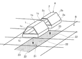
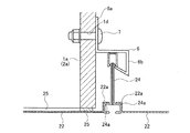
以下、この発明の実施の形態例1のグリッド型システム天井(以下、単に『システム天井』と言う)Bの空調用チャンバー装置Aを図に基づいて説明する。このシステム天井Bの空調用チャンバー装置Aは、図1及び図2に示す様に、システム天井Bの天井裏に空調用のチャンバー装置Aを設置し、このチャンバー装置A内に機械室の空調機Cから送られてきた空調空気を送り込んで、放射板となる天井面を形成する板体22を冷却又は加熱するものであって、概略、チャンバー装置Aを形成する複数の、グラスウールボードから成るボックス1(2、3)と天井面と成る板体22から形成される。
C 空調機
1 ボックス 1a 枠体 1b 屋根
1c 開口面 1d 通孔 2 先端ボックス
2a 枠体 2b 屋根 2c 開口面
3 後端ボックス 3a 枠体 3b 屋根
3c 開口面 3d 開口部 4 パッキン
5 留め金 6 転倒防止具 6a 一片
6b 他片 7 ボルト
21 グリッド 22 板体 22a 段部
23 通孔 24 Tバー 24a 段部
25 ダクト
Claims (4)
- グリッド型システム天井において使用する空調用チャンバー装置において、
前記グリッドの開口と底面が略同形同大に開口し、下部は平面視方形形状で一定長の高さを有する枠体の上に、前後が開口した屋根を設けた略筒状のボックスを形成し、
前記ボックスの枠体の、前記屋根の開口部の下に位置する両端の外側端面下部の一側から他側にわたって凹部を設け、
複数の連続した前記グリッド毎に多数の通孔を有する天井面を形成する板体を嵌め、その上から前記ボックスを被せて複数連続設置し、これらの隣接する各ボックスは、枠体の一対の両端の外側端面下部の前記凹部が相対向するように並べ、当該相対向する凹部内に、グリッドの一辺を成すTバーを収納させて隣接する各ボックスの枠体の外側端面及び屋根の端部を突き合わせて密着接続し、
前記ボックスのうち前端に設置されるボックスの前端面を塞ぎ、後端に設置されるボックスの後面の開口面に空調機と接続されたダクトの供給口を接続して前記各ボックスを通じて各グリッド内に空調空気を送り、当該空調空気のうち下層を移送するものは前記ボックスの枠体に衝突して下降し、前記板体と接触し、また、当該空気の一部は前記板体の通孔を通過して当該板体を冷却又は加熱させる構成であることを特徴とした、グリッド型システム天井の空調用チャンバー装置。 - 前記各ボックスの屋根形状は、上部の断面が上へ行くほど幅が狭くなる台形状としたことを特徴とする、前記請求項1に記載のシステム天井空調用チャンバー装置。
- 前記ボックス同士の接続面及び各板体と各ボックスの枠体の接触面には夫々パッキンを設け、各ボックス同士は固定具で固定したことを特徴とする、前記請求項1又は2の何れかに記載のシステム天井空調用チャンバー装置。
- 前記ボックスの両側面の枠体に、略クランク型の転倒防止具の一片を取り付けて垂下させ、当該転倒防止具の他片の鍵片を前記システム天井から立設しているTバーの頭部に下方から引っ掛けて取り付けたことを特徴とする、前記請求項1、2又は3の何れかに記載のシステム天井空調用チャンバー装置。
Priority Applications (1)
| Application Number | Priority Date | Filing Date | Title |
|---|---|---|---|
| JP2013167727A JP6238637B2 (ja) | 2013-08-12 | 2013-08-12 | グリッド型システム天井の空調用チャンバー装置 |
Applications Claiming Priority (1)
| Application Number | Priority Date | Filing Date | Title |
|---|---|---|---|
| JP2013167727A JP6238637B2 (ja) | 2013-08-12 | 2013-08-12 | グリッド型システム天井の空調用チャンバー装置 |
Publications (2)
| Publication Number | Publication Date |
|---|---|
| JP2015036592A JP2015036592A (ja) | 2015-02-23 |
| JP6238637B2 true JP6238637B2 (ja) | 2017-11-29 |
Family
ID=52687156
Family Applications (1)
| Application Number | Title | Priority Date | Filing Date |
|---|---|---|---|
| JP2013167727A Active JP6238637B2 (ja) | 2013-08-12 | 2013-08-12 | グリッド型システム天井の空調用チャンバー装置 |
Country Status (1)
| Country | Link |
|---|---|
| JP (1) | JP6238637B2 (ja) |
Families Citing this family (1)
| Publication number | Priority date | Publication date | Assignee | Title |
|---|---|---|---|---|
| JP6618715B2 (ja) * | 2015-06-19 | 2019-12-11 | 協立エアテック株式会社 | 空調用チャンバー設置構造 |
Family Cites Families (10)
| Publication number | Priority date | Publication date | Assignee | Title |
|---|---|---|---|---|
| US3835606A (en) * | 1972-05-22 | 1974-09-17 | M Liberman | Combination ceiling tile and air duct structure |
| JPS6097918U (ja) * | 1983-12-10 | 1985-07-04 | 松下電工株式会社 | 天井取付け用機器の取付け構造 |
| JPH0240408Y2 (ja) * | 1985-08-30 | 1990-10-29 | ||
| JP2594543Y2 (ja) * | 1992-05-15 | 1999-04-26 | 松下電工株式会社 | 空調用天井枠材 |
| JPH0618841U (ja) * | 1992-08-07 | 1994-03-11 | 株式会社大林組 | ダクト兼用天井パネルの連結構造 |
| US5281187A (en) * | 1992-11-09 | 1994-01-25 | Whitney Jr Harry R | Unitary vent and duct assembly |
| JPH07145959A (ja) * | 1993-11-19 | 1995-06-06 | Hibiya Eng Ltd | 天井通気式空調装置 |
| JPH08247488A (ja) * | 1995-03-07 | 1996-09-27 | Sanyo Electric Co Ltd | 輻射冷却装置 |
| JP3759777B2 (ja) * | 1995-12-28 | 2006-03-29 | 大和ハウス工業株式会社 | 天井空調装置 |
| JP2003194390A (ja) * | 2001-12-27 | 2003-07-09 | Mitsubishi Electric Corp | 空気調和システム |
-
2013
- 2013-08-12 JP JP2013167727A patent/JP6238637B2/ja active Active
Also Published As
| Publication number | Publication date |
|---|---|
| JP2015036592A (ja) | 2015-02-23 |
Similar Documents
| Publication | Publication Date | Title |
|---|---|---|
| CN104254814A (zh) | 空调系统 | |
| CN107091507B (zh) | 空调装置 | |
| KR101078605B1 (ko) | 복사 냉난방 시스템 및 그 시공방법 | |
| JP2011149677A (ja) | 全空気方式天井冷暖房システム | |
| JP2014134301A (ja) | 天井空調ユニット及びこれを用いた空調システム | |
| EP2495377A1 (en) | Heat transfer element and method for constructing a heating or cooling system of a space | |
| JP2015036592A (ja) | グリッド型システム天井の空調用チャンバー装置 | |
| JP7468870B2 (ja) | 床ふく射対流式冷暖房システム | |
| JP6153203B2 (ja) | 熱交換構造体、および、熱交換構造体の施工方法 | |
| JP2015218947A (ja) | 空調システム | |
| CN109690203B (zh) | 空调装置 | |
| JP6625358B2 (ja) | 空調システム | |
| JP5081023B2 (ja) | 建物の空調設備及びそれを備えた建物 | |
| CN106948535A (zh) | 建筑物的屋顶与墙壁的通风及隔热结构 | |
| JP2013228161A (ja) | サーバ室の空調設備 | |
| JP6874960B2 (ja) | 輻射式空調ユニット及びこれを用いた輻射式空調装置 | |
| JP7168470B2 (ja) | 建物 | |
| JP7278183B2 (ja) | 建築物の空調システム | |
| JP7017929B2 (ja) | 空調システム | |
| JP7286830B2 (ja) | パーソナル空調システム | |
| JP6618715B2 (ja) | 空調用チャンバー設置構造 | |
| JP7168530B2 (ja) | 床吹出放射空調システム | |
| JP7033486B2 (ja) | パーソナル空調システム | |
| JP2011002105A (ja) | 天井輻射式空調システム | |
| JP3602110B2 (ja) | 住宅用全空気方式床冷暖房システム |
Legal Events
| Date | Code | Title | Description |
|---|---|---|---|
| A621 | Written request for application examination |
Free format text: JAPANESE INTERMEDIATE CODE: A621 Effective date: 20160808 |
|
| A977 | Report on retrieval |
Free format text: JAPANESE INTERMEDIATE CODE: A971007 Effective date: 20170419 |
|
| A131 | Notification of reasons for refusal |
Free format text: JAPANESE INTERMEDIATE CODE: A131 Effective date: 20170502 |
|
| A521 | Request for written amendment filed |
Free format text: JAPANESE INTERMEDIATE CODE: A523 Effective date: 20170630 |
|
| TRDD | Decision of grant or rejection written | ||
| A01 | Written decision to grant a patent or to grant a registration (utility model) |
Free format text: JAPANESE INTERMEDIATE CODE: A01 Effective date: 20171003 |
|
| A61 | First payment of annual fees (during grant procedure) |
Free format text: JAPANESE INTERMEDIATE CODE: A61 Effective date: 20171031 |
|
| R150 | Certificate of patent or registration of utility model |
Ref document number: 6238637 Country of ref document: JP Free format text: JAPANESE INTERMEDIATE CODE: R150 |
|
| R250 | Receipt of annual fees |
Free format text: JAPANESE INTERMEDIATE CODE: R250 |
|
| R250 | Receipt of annual fees |
Free format text: JAPANESE INTERMEDIATE CODE: R250 |
|
| R250 | Receipt of annual fees |
Free format text: JAPANESE INTERMEDIATE CODE: R250 |
|
| R250 | Receipt of annual fees |
Free format text: JAPANESE INTERMEDIATE CODE: R250 |
|
| R250 | Receipt of annual fees |
Free format text: JAPANESE INTERMEDIATE CODE: R250 |
|
| R250 | Receipt of annual fees |
Free format text: JAPANESE INTERMEDIATE CODE: R250 |
|
| R250 | Receipt of annual fees |
Free format text: JAPANESE INTERMEDIATE CODE: R250 |