JP6242515B1 - Structure diagnosis method - Google Patents
Structure diagnosis method Download PDFInfo
- Publication number
- JP6242515B1 JP6242515B1 JP2017014663A JP2017014663A JP6242515B1 JP 6242515 B1 JP6242515 B1 JP 6242515B1 JP 2017014663 A JP2017014663 A JP 2017014663A JP 2017014663 A JP2017014663 A JP 2017014663A JP 6242515 B1 JP6242515 B1 JP 6242515B1
- Authority
- JP
- Japan
- Prior art keywords
- camera
- image
- cameras
- state
- moving means
- Prior art date
- Legal status (The legal status is an assumption and is not a legal conclusion. Google has not performed a legal analysis and makes no representation as to the accuracy of the status listed.)
- Active
Links
Images


Classifications
-
- Y—GENERAL TAGGING OF NEW TECHNOLOGICAL DEVELOPMENTS; GENERAL TAGGING OF CROSS-SECTIONAL TECHNOLOGIES SPANNING OVER SEVERAL SECTIONS OF THE IPC; TECHNICAL SUBJECTS COVERED BY FORMER USPC CROSS-REFERENCE ART COLLECTIONS [XRACs] AND DIGESTS
- Y02—TECHNOLOGIES OR APPLICATIONS FOR MITIGATION OR ADAPTATION AGAINST CLIMATE CHANGE
- Y02A—TECHNOLOGIES FOR ADAPTATION TO CLIMATE CHANGE
- Y02A10/00—TECHNOLOGIES FOR ADAPTATION TO CLIMATE CHANGE at coastal zones; at river basins
- Y02A10/11—Hard structures, e.g. dams, dykes or breakwaters
Landscapes
- Testing Of Devices, Machine Parts, Or Other Structures Thereof (AREA)
- Investigating Materials By The Use Of Optical Means Adapted For Particular Applications (AREA)
- Bridges Or Land Bridges (AREA)
- Revetment (AREA)
Abstract
【課題】簡易かつ安価に既存構造物の状況を確認することを可能とした構造物診断方法を提案する。【解決手段】同一直線上に並設された複数のカメラ3で上部工11の下面を撮影する撮影工程と、カメラ3で撮影した画像により上部工11の下面の状況を確認する診断工程とを備える構造物診断方法であって、一のカメラ3によって撮影する範囲が、隣接する他のカメラ3によって撮影する範囲の少なくとも一部と重なっており、診断工程では、隣り合うカメラ3の画像同士を重ね合わせることで上部工11の下面の状況を広範囲に確認する。【選択図】図1The present invention proposes a method for diagnosing a structure that enables simple and inexpensive confirmation of the state of an existing structure. An imaging step of photographing the lower surface of the upper work 11 with a plurality of cameras 3 arranged side by side on the same straight line, and a diagnostic step of confirming the state of the lower surface of the upper work 11 from an image taken by the camera 3 In the structure diagnosis method, a range captured by one camera 3 overlaps at least a part of a range captured by another adjacent camera 3, and in the diagnosis process, images of adjacent cameras 3 are captured. The state of the lower surface of the upper work 11 is confirmed over a wide range by overlapping. [Selection] Figure 1
Description
本発明は、構造物診断方法に関する。 The present invention relates to a structure diagnostic method.
コンクリート構造物の劣化の診断方法として、構造物の表面に生じたクラックや欠損などを確認する方法が知られている。構造物のクラック等の確認は、目視による確認が一般的である。ところが、例えば港湾構造物等のように、測定者が近づくことが困難な場合には、目視により確認することができない場合がある。そのため、特許文献1には、小型船舶等に設置したカメラで撮影した画像により港湾構造物の劣化状況を診断する方法が開示されている。
As a method for diagnosing deterioration of a concrete structure, a method for confirming cracks or defects generated on the surface of the structure is known. The confirmation of cracks and the like of the structure is generally a visual confirmation. However, when it is difficult for the measurer to approach, such as a port structure, it may not be visually confirmed. Therefore,
前記従来の診断方法は、カメラの撮影方向を多方向に変化させてランダムに撮影することで撮影対象範囲の全体を撮影するものである。そのため、カメラの撮影方向を制御するための複雑な機構を備えている必要があり、装置が高価である。 In the conventional diagnostic method, the entire photographing target range is photographed by randomly photographing while changing the photographing direction of the camera in multiple directions. Therefore, it is necessary to provide a complicated mechanism for controlling the shooting direction of the camera, and the apparatus is expensive.
このような観点から、本発明は、簡易かつ安価に既存構造物の状況を確認することを可能とした構造物診断方法を提案することを課題とする。 From such a point of view, an object of the present invention is to propose a structure diagnosis method that can easily and inexpensively confirm the status of an existing structure.
前記課題を解決するための本発明は、水上の移動手段に搭載されているとともに、当該移動手段の真上に向けた状態で同一直線上に並設された複数のカメラで同時に構造物を撮影する撮影工程と、前記カメラで撮影した画像により前記構造物の表面の状況を確認する診断工程とを備える構造物診断方法であって、前記複数のカメラは、前記移動手段に固定された棒状の取付部材に固定されていることで、ジンバル等の撮影方向調整機構を用いることなく前記移動手段に固定されており、前記取付部材は、前記移動手段の進行方向に対して直交していて、前記複数のカメラの撮影方向同士は平行で、かつ、一のカメラによって撮影する範囲が隣接する他のカメラによって撮影する範囲の少なくとも一部と重なっており、前記診断工程では隣り合うカメラの画像同士を重ね合わせることで前記構造物の表面の状況を広範囲に確認することを特徴とする。なお、前記撮影工程では、前記カメラによって動画を撮影するものとし、前記診断工程では、前記動画から抽出した静止画同士を接続して大きな画像を作成するのが望ましい。 The present invention for solving the above-described problems is mounted on the moving means on the water, and simultaneously photographs a structure with a plurality of cameras arranged in parallel on the same straight line in a state of being directly above the moving means. And a diagnostic process for confirming the condition of the surface of the structure based on an image captured by the camera , wherein the plurality of cameras are rod-shaped fixed to the moving means. By being fixed to the mounting member, it is fixed to the moving means without using a photographing direction adjusting mechanism such as a gimbal, and the mounting member is orthogonal to the traveling direction of the moving means, and photographing direction between the plurality of cameras are parallel, and overlaps with at least a portion of the range to be captured by other cameras to adjacent shooting range by one camera, next in the diagnostic step if Characterized by check extensively the status of the surface of the structure by superimposing the images to each other camera. In the imaging step, a moving image is taken by the camera, and in the diagnosis step, it is desirable to create a large image by connecting still images extracted from the moving image.
かかる構造物診断方法によれば、複数の画像をラップさせた状態で大きな画像を作成して構造物表面全体の状況を判断するため、より正確に構造物の表面を確認することができる。また、複数のカメラを利用して広範囲に撮影することができるため、カメラの撮影方向を操作するための複雑な機構を要しない。また、1回の走行または航行により広範囲に構造物の表面の状況を確認することができる。なお、前記診断工程において、前記画像同士の重なる部分において前記構造物の表面の状況を確認すれば、複数の画像を重ね合わせることによって凹凸が強調されるため、クラック等を確認しやすい。 According to such a structure diagnosis method, a large image is created in a state where a plurality of images are wrapped, and the state of the entire structure surface is judged. Therefore, the surface of the structure can be confirmed more accurately. In addition, since a wide range of images can be taken using a plurality of cameras, a complicated mechanism for operating the shooting direction of the cameras is not required. In addition, the state of the surface of the structure can be confirmed in a wide range by one run or navigation. In the diagnostic step, if the surface condition of the structure is confirmed in the overlapping portion of the images, the unevenness is emphasized by superimposing a plurality of images, so that cracks and the like can be easily confirmed.
本発明の構造物診断方法によれば、簡易かつ安価に既存構造物の状況を確認することが可能となる。 According to the structure diagnosis method of the present invention, it is possible to check the state of an existing structure easily and inexpensively.
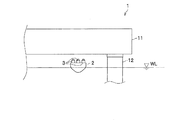
本実施形態では、桟橋1の保全点検を目的として、上部工(構造物)11の下面の劣化を診断する場合について説明する(図1参照)。本実施形態の構造物診断方法は、上部工11の下面をカメラで撮影して画像を採取する撮影工程と、撮影工程で撮影した画像により上部工の下面の状況を確認する診断工程とを備えている。なお、図1において、符号12は、上部工11を支持する下部工である。
This embodiment demonstrates the case where the deterioration of the lower surface of the superstructure (structure) 11 is diagnosed for the purpose of the maintenance inspection of the pier 1 (refer FIG. 1). The structure diagnosis method of the present embodiment includes an imaging process for capturing an image by capturing an image of the lower surface of the
撮影工程では、図2に示すように、複数のカメラ3,3,3が搭載された台船2を利用して、桟橋1の下側の水上から上部工11の下面を撮影する。本実施形態の台船2は、遠隔操作が可能な無人小型艇である。なお、台船2の構成、形状、大きさ等は限定されるものではなく、適宜決定すればよい。また、台船2の操作は、離れた位置から台船2の位置を確認しながら行ってもよいし、台船2に搭載されたカメラ(図示せず)の画像を、陸上に設けられたモニターで確認しながら行ってもよい。また、台船2は、予め設定されたルートを自動的に走行するように制御してもよい。
In the photographing process, as shown in FIG. 2, the lower surface of the
台船2に搭載された複数(本実施形態では3台)のカメラ3,3,3は、台船2の真上に向けた状態で、同一直線状に並設されている。カメラ3は台船に固定された棒状の取付部材4に固定されている。取付部材4の長手方向は、台船2の進行方向に対して直交している。また、カメラ3の撮影方向は、取付部材4の長手方向および台船2の進行方向に対して直交しており、各カメラの撮影方向同士は平行である。なお、台船2に設置されるカメラ3の台数は2台以上であれば限定されるものではない。
A plurality of (three in this embodiment) cameras 3, 3, 3 mounted on the
上部工11の下面の撮影は、台船2を桟橋1の下側に侵入させた状態で行う。本実施形態では、動画を撮影するものとし、複数のカメラ3,3,3は同時に撮影を行うように制御されている。撮影工程では、台船2を移動させつつ、動画を撮影することで、上部工11の下面全体を撮影する。なお、撮影工程では、静止画を撮影してもよい。カメラ3は、遠隔操作により撮影するようにしてもよいし、予め設定されたプログラムに基づいて自動的に撮影するようにしてもよい。
The lower surface of the
複数のカメラ3,3,3は、図3に示すように、一のカメラ3によって撮影する範囲(撮影範囲31)の一部が、隣接する他のカメラ3によって撮影する範囲(撮影範囲32,33)の一部と重なるように配置されている。本実施形態では、隣り合うカメラ3同士の撮影範囲が65%以上重なり合っている(重複範囲30)。なお、隣り合うカメラ3同士の重なり合う範囲(重複範囲30)の割合は限定されるものではなく適宜設定すればよい。 As shown in FIG. 3, the plurality of cameras 3, 3, and 3 are configured such that a part of a range (shooting range 31) shot by one camera 3 is shot by another adjacent camera 3 (shooting ranges 32, 32). 33) is arranged so as to overlap a part. In the present embodiment, the shooting ranges of adjacent cameras 3 overlap each other by 65% or more (overlap range 30). In addition, the ratio of the overlapping range (overlapping range 30) of the adjacent cameras 3 is not limited and may be set as appropriate.
台船2は、上部工11を横断する方向で移動させつつ、複数回折り返すことで、上部工11の下面全体を撮影する。
The
診断工程では、まず、撮影工程において撮影した動画から、1秒間に3枚の静止画を抽出する。次に隣接する撮影画像同士の重複する部分(重複範囲30)において、画像同士をラップさせることで、広範囲の画像(診断用画像)を作成する。なお、動画から抽出する静止画の1秒あたりの枚数は限定されるものではなく、適宜決定すればよい。 In the diagnosis step, first, three still images are extracted per second from the moving image shot in the shooting step. Next, a wide range of images (diagnostic images) is created by wrapping the images in the overlapping portion (overlapping range 30) between adjacent captured images. Note that the number of still images extracted from a moving image per second is not limited, and may be determined as appropriate.
診断用画像の作成には、SfM(Structure from Motion)技術を用いる。ここで、「SfM技術」とは、カメラの視点を変えながら撮影した複数の画像からそのシーンの3次元形状とカメラの位置を同時に復元する手法である。本実施形態では、Agisoft社製のPhotoscanを使用して、撮影画像から診断用画像を作成する。なお、診断用画像の作成に使用するソフトは、SfM技術を用いるものであれば限定されるものではない。 SfM (Structure from Motion) technology is used to create a diagnostic image. Here, the “SfM technology” is a technique for simultaneously restoring the three-dimensional shape of the scene and the position of the camera from a plurality of images taken while changing the viewpoint of the camera. In this embodiment, a diagnostic image is created from a photographed image using Photoscan manufactured by Agisoft. The software used for creating the diagnostic image is not limited as long as it uses the SfM technology.
以上、本実施形態の構造物診断方法によれば、台船2を利用して撮影した画像により構造物の劣化状況(ひびわれ、浸食、破損等)を確認するため、目視が困難な桟橋1の上部工11の下面を評価することができる。
As described above, according to the structure diagnosis method of the present embodiment, the deterioration state (cracking, erosion, breakage, etc.) of the structure is confirmed by the image taken using the
また、画像同士を重ね合わせることで、上部工の状態を広範囲に確認することができる。すなわち、1枚の画像のみでは影等により見えにくい部分に対しても、把握することができる。なお、撮影工程において撮影した画像は、撮影範囲が隣接する他の画像と65%以上重複しているため、上部工の下面の全体を重ね合わせた画像により確認することができる。また、異なる方向から撮影された画像同士を重ね合わせることで、上部工の下面の凹凸を3次元的に確認することができる。 In addition, by superimposing the images, the state of the superstructure can be confirmed over a wide range. That is, it is possible to grasp even a portion that is difficult to see due to a shadow or the like with only one image. In addition, since the image image | photographed in the imaging | photography process has overlapped 65% or more with the other image which the imaging | photography range adjoins, it can confirm with the image which overlap | superposed the whole lower surface of the superstructure. Moreover, the unevenness | corrugation of the lower surface of a superstructure can be confirmed three-dimensionally by superimposing the image image | photographed from different directions.
また、複数のカメラを利用して広範囲に撮影することで、カメラ3の撮影方向を制御する複雑な機構を必要としないため、コストの低減化が可能である。また、ジンバル等のカメラ3の撮影方向を一定に保つための機構も省略することで、設備の簡略化および費用の低減化を図ることができる。また、構造物の状況を1走行(1回の走行または1回の航行)により広範囲に確認することができる。 In addition, by photographing a wide range using a plurality of cameras, a complicated mechanism for controlling the photographing direction of the camera 3 is not required, so that the cost can be reduced. Further, by omitting a mechanism for keeping the photographing direction of the camera 3 such as a gimbal constant, it is possible to simplify equipment and reduce costs. Further, the state of the structure can be confirmed in a wide range by one run (one run or one trip).
また、画像同士を重ねることで、1枚の画像では不鮮明な部分を、他の画像を足し合わせることで補うことができる。すなわち、複数の画像データの画素を組み合わせることで、構造物表面の凹凸が強調されるため、クラック等を確認しやすくなる。なお、撮影工程において撮影した画像は、撮影範囲が隣接する他の画像と65%以上重複しているため、上部工の下面の全体を重ね合わせた画像により確認することができる。 In addition, by superimposing images, an unclear portion of one image can be compensated by adding other images. That is, by combining the pixels of the plurality of image data, the unevenness on the surface of the structure is emphasized, so that it is easy to confirm cracks and the like. In addition, since the image image | photographed in the imaging | photography process has overlapped 65% or more with the other image which the imaging | photography range adjoins, it can confirm with the image which overlap | superposed the whole lower surface of the superstructure.
以上、本発明に係る実施形態について説明した。しかし、本発明は、前述の実施形態に限られず、前記の各構成要素については、本発明の趣旨を逸脱しない範囲で、適宜変更が可能である。
例えば、前記実施形態では、桟橋1の上部工11の調査を行う場合について説明したが、構造物診断方法によって調査を行う対象の構造物は桟橋1に限定されるものではなく、例えば、橋梁等であってもよい。
The embodiment according to the present invention has been described above. However, the present invention is not limited to the above-described embodiment, and the above-described components can be appropriately changed without departing from the spirit of the present invention.
For example, in the above-described embodiment, the case where the
また、前記実施形態では、台船2を利用して水面から調査を行う場合について説明したが、移動手段は台船2に限定されるものではない。例えば、陸上であれば車輪等の走行手段を備えたものであってもよい。
また、カメラ3の向きは、必ずしも真上に限定されるものではなく、撮影の対象となる構造物に応じて適宜決定すればよい。
Moreover, although the said embodiment demonstrated the case where the investigation was carried out from the water surface using the
Further, the orientation of the camera 3 is not necessarily limited to the above, and may be determined as appropriate according to the structure to be photographed.
1 桟橋
11 上部工(構造物)
2 台船(移動手段)
3 カメラ
1
2 boats (transportation)
3 Camera
Claims (3)
前記カメラで撮影した画像により前記構造物の表面の状況を確認する診断工程と、を備える構造物診断方法であって、
前記複数のカメラは、前記移動手段に固定された棒状の取付部材に固定されていることで、撮影方向調整機構を用いることなく前記移動手段に固定されており、
前記取付部材は、前記移動手段の進行方向に対して直交していて、
前記複数のカメラの撮影方向同士は平行で、かつ、一のカメラによって撮影する範囲が、隣接する他のカメラによって撮影する範囲の少なくとも一部と重なっており、
前記診断工程では、隣り合うカメラの画像同士を重ね合わせることで前記構造物の表面の状況を広範囲に確認することを特徴とする、構造物診断方法。 An imaging process for simultaneously photographing a structure with a plurality of cameras mounted on the moving means on the water and arranged in parallel on the same straight line in a state directed directly above the moving means;
A diagnostic process for confirming the state of the surface of the structure from an image photographed by the camera, and a structure diagnostic method comprising:
The plurality of cameras are fixed to the moving means without using a photographing direction adjusting mechanism by being fixed to a rod-like attachment member fixed to the moving means,
The attachment member is orthogonal to the traveling direction of the moving means,
The shooting directions of the plurality of cameras are parallel to each other, and a range shot by one camera overlaps at least a part of a range shot by another adjacent camera,
In the diagnosis step, the structure diagnosis method is characterized in that the state of the surface of the structure is confirmed over a wide range by superimposing images of adjacent cameras.
前記診断工程では、前記動画から抽出した静止画同士を接続して大きな画像を作成することを特徴とする、請求項1に記載の構造物診断方法。 In the shooting process, a video is shot by the camera,
2. The structure diagnosis method according to claim 1, wherein in the diagnosis step, a still image extracted from the moving image is connected to create a large image.
Priority Applications (1)
| Application Number | Priority Date | Filing Date | Title |
|---|---|---|---|
| JP2017014663A JP6242515B1 (en) | 2017-01-30 | 2017-01-30 | Structure diagnosis method |
Applications Claiming Priority (1)
| Application Number | Priority Date | Filing Date | Title |
|---|---|---|---|
| JP2017014663A JP6242515B1 (en) | 2017-01-30 | 2017-01-30 | Structure diagnosis method |
Publications (2)
| Publication Number | Publication Date |
|---|---|
| JP6242515B1 true JP6242515B1 (en) | 2017-12-06 |
| JP2018124092A JP2018124092A (en) | 2018-08-09 |
Family
ID=60570444
Family Applications (1)
| Application Number | Title | Priority Date | Filing Date |
|---|---|---|---|
| JP2017014663A Active JP6242515B1 (en) | 2017-01-30 | 2017-01-30 | Structure diagnosis method |
Country Status (1)
| Country | Link |
|---|---|
| JP (1) | JP6242515B1 (en) |
Cited By (2)
| Publication number | Priority date | Publication date | Assignee | Title |
|---|---|---|---|---|
| CN109490803A (en) * | 2018-10-16 | 2019-03-19 | 清华大学 | Super structure surface device and preparation method, MRI system |
| JP7752370B1 (en) * | 2025-03-14 | 2025-10-10 | 西部マリン・サービス株式会社 | Water-based inspection device and water-based inspection method |
Families Citing this family (1)
| Publication number | Priority date | Publication date | Assignee | Title |
|---|---|---|---|---|
| KR102076775B1 (en) * | 2019-06-14 | 2020-02-12 | 주식회사 한국건설방재연구원 | Unmanned Air Boat for Safety Inspection of Sub-Bottom of Landing Pier and Inside of Medium-Large Sized Culvert |
Family Cites Families (8)
| Publication number | Priority date | Publication date | Assignee | Title |
|---|---|---|---|---|
| JP2002156347A (en) * | 2000-11-15 | 2002-05-31 | Mitsubishi Heavy Ind Ltd | Structure inspection device, carrier car for inspecting structure, and structure inspection method |
| JP2002267432A (en) * | 2001-03-14 | 2002-09-18 | Nishimatsu Constr Co Ltd | Damage detection method for tunnel lining surface |
| US7463348B2 (en) * | 2006-07-10 | 2008-12-09 | General Electric Company | Rail vehicle mounted rail measurement system |
| JP5628068B2 (en) * | 2011-02-25 | 2014-11-19 | 三協エンジニアリング株式会社 | Tunnel wall development image acquisition system |
| JP2014062433A (en) * | 2012-09-24 | 2014-04-10 | Hitachi Ltd | Structure imaging method |
| JP2015119372A (en) * | 2013-12-19 | 2015-06-25 | 株式会社日立製作所 | Multi-camera photographing system and method of combining multi-camera photographic images |
| JP2015219014A (en) * | 2014-05-14 | 2015-12-07 | コニカミノルタ株式会社 | Object diagnostic system |
| JP6534093B2 (en) * | 2015-02-02 | 2019-06-26 | 五洋建設株式会社 | Floating observation device and inspection method of structure using the same |
-
2017
- 2017-01-30 JP JP2017014663A patent/JP6242515B1/en active Active
Cited By (2)
| Publication number | Priority date | Publication date | Assignee | Title |
|---|---|---|---|---|
| CN109490803A (en) * | 2018-10-16 | 2019-03-19 | 清华大学 | Super structure surface device and preparation method, MRI system |
| JP7752370B1 (en) * | 2025-03-14 | 2025-10-10 | 西部マリン・サービス株式会社 | Water-based inspection device and water-based inspection method |
Also Published As
| Publication number | Publication date |
|---|---|
| JP2018124092A (en) | 2018-08-09 |
Similar Documents
| Publication | Publication Date | Title |
|---|---|---|
| US20230228694A1 (en) | Systems and methods for inspecting pipelines using a pipeline inspection robot | |
| US11587217B2 (en) | Systems and methods for inspecting pipelines using a robotic imaging system | |
| JP6574845B2 (en) | Drawing creating apparatus and drawing creating method | |
| JP6242515B1 (en) | Structure diagnosis method | |
| JP5868681B2 (en) | Remote control vehicle system | |
| JP2012098170A (en) | Image data processing system | |
| CN112425148B (en) | Imaging device, unmanned moving body, imaging method, system, and recording medium | |
| CN110073415A (en) | Surround View System for Vehicles | |
| JP6725675B2 (en) | Self-position estimating device, self-position estimating method, program, and image processing device | |
| WO2011040239A1 (en) | Wide angle imaging device and measurement system | |
| TW201701235A (en) | Method for adjusting vehicle panorama system | |
| JP2018188043A (en) | Maneuvering support device | |
| JP2017025485A (en) | Structure inspection apparatus and structure inspection method | |
| JP6482856B2 (en) | Monitoring system | |
| US10742874B2 (en) | Imaging plan generation device, imaging plan generation method, and program | |
| JP6482855B2 (en) | Monitoring system | |
| JP6256874B2 (en) | Overhead image display device for construction machinery | |
| JP2020082830A (en) | Artificial satellite, observation system, and information processing device | |
| JP2017096654A (en) | Shooting system | |
| JP6650753B2 (en) | Image acquisition system and image acquisition method | |
| JP2016208294A (en) | Multiple-image photographing system, photographing apparatus, and image processing apparatus | |
| JP4551990B2 (en) | Panorama video creation method and creation device | |
| CN115981364A (en) | A method and system for controlling the pan-tilt of an inspection UAV | |
| KR101420305B1 (en) | Automotive omnidirectional monitoring apparatus | |
| JPWO2018180214A1 (en) | Image processing apparatus, camera apparatus, and image processing method |
Legal Events
| Date | Code | Title | Description |
|---|---|---|---|
| TRDD | Decision of grant or rejection written | ||
| A01 | Written decision to grant a patent or to grant a registration (utility model) |
Free format text: JAPANESE INTERMEDIATE CODE: A01 Effective date: 20171024 |
|
| A61 | First payment of annual fees (during grant procedure) |
Free format text: JAPANESE INTERMEDIATE CODE: A61 Effective date: 20171107 |
|
| R150 | Certificate of patent or registration of utility model |
Ref document number: 6242515 Country of ref document: JP Free format text: JAPANESE INTERMEDIATE CODE: R150 |
|
| R250 | Receipt of annual fees |
Free format text: JAPANESE INTERMEDIATE CODE: R250 |
|
| R250 | Receipt of annual fees |
Free format text: JAPANESE INTERMEDIATE CODE: R250 |