JP6242580B2 - Composite molded body - Google Patents
Composite molded body Download PDFInfo
- Publication number
- JP6242580B2 JP6242580B2 JP2013074739A JP2013074739A JP6242580B2 JP 6242580 B2 JP6242580 B2 JP 6242580B2 JP 2013074739 A JP2013074739 A JP 2013074739A JP 2013074739 A JP2013074739 A JP 2013074739A JP 6242580 B2 JP6242580 B2 JP 6242580B2
- Authority
- JP
- Japan
- Prior art keywords
- molded body
- polypropylene
- layer
- transparent
- base material
- Prior art date
- Legal status (The legal status is an assumption and is not a legal conclusion. Google has not performed a legal analysis and makes no representation as to the accuracy of the status listed.)
- Active
Links
Images

Landscapes
- Laminated Bodies (AREA)
- Injection Moulding Of Plastics Or The Like (AREA)
Description
本発明は、複合成型体に関する。 The present invention relates to a composite molded body.
従来から射出成型体の表面に絵柄等の装飾を付与した加飾成形品が各種用途に使用されている。
このような加飾成形品としては、アクリル樹脂やポリプロピレンなどの透明樹脂材料の片面に加飾印刷を施して加飾層を形成し、この加飾層の印刷面に樹脂基材を射出成形などによって一体化して基材層を形成した表面加飾成形体が知られている(例えば、特許文献1参照)。
2. Description of the Related Art Conventionally, a decorative molded product in which a decoration such as a pattern is provided on the surface of an injection molded body has been used for various purposes.
As such a decorative molded product, a decorative layer is formed by performing decorative printing on one surface of a transparent resin material such as acrylic resin or polypropylene, and a resin base material is injection-molded on the printed surface of this decorative layer. There is known a surface-decorated molded body that is integrated by forming a base material layer (see, for example, Patent Document 1).
しかし、上記特許文献1に記載の表面加飾成形体の層構成では、加飾層と基材層との接着性に劣り、剥離を生じるおそれがあった。
本発明の目的は、透明成型体と射出成型体との接着性に優れた、複合成型体を提供することである。
However, in the layer configuration of the surface decorative molded article described in Patent Document 1, the adhesion between the decorative layer and the base material layer is inferior, and there is a risk of peeling.
An object of the present invention is to provide a composite molded body having excellent adhesion between a transparent molded body and an injection molded body.
前記課題を解決すべく、本発明は、以下のような複合成型体を提供するものである。
すなわち、本発明の複合成型体は、ポリプロピレンからなる基材層と、ポリプロピレンからなる溶着層と、の少なくとも2層からなる透明成型体と、射出成形により得られた射出成型体と、を備え、前記基材層のポリプロピレンは、示差走査型熱量分析(Differential Scanning Calorimetry:DSC)にて測定した融解エンタルピー(ΔH)が60J/g以上200J/g以下であり、前記溶着層のポリプロピレンは、前記融解エンタルピー(ΔH)が10J/g以上55J/g以下であり、前記透明成型体と前記射出成型体とが前記溶着層を介して接合されてなることを特徴とするものである。
さらに、本発明の複合成型体は、ポリプロピレンからなる基材層と、ポリプロピレンからなる溶着層と、の少なくとも2層からなる透明成型体と、射出成形により得られた射出成型体と、を備え、前記基材層のポリプロピレンは、アイソタクチックペンタッド分率が80%以上であり、前記溶着層のポリプロピレンは、アイソタクチックペンタッド分率が10%以上75%以下であり、前記透明成型体と前記射出成型体とが前記溶着層を介して接合されてなることを特徴とするものである。
本発明のポリプロピレンからなる基材層とは、溶着層を介して射出成型体と接合される層である。この基材層は、透明性に優れ、溶着層に比べ、耐熱が高く、硬度が高い材料から構成される。基材層を構成する好ましい材料としては、ホモポリプロピレン、プロピレン−エチレンランダム共重合体、プロピレン−エチレンブロック共重合体などが挙げられる。好ましい製法としては、例えば、シングルベルトプロセスによる急冷法や造核剤の添加による方法などが挙げられる。
本発明のポリプロピレンからなる溶着層とは、射出成型体との密着性に優れた層である。溶着層には、基材層に係る材料に比べ、溶融エンタルピーの低い材料が用いられ、当該層が用いられることにより、当該透明成型体と前記射出成型体と、が接合されやすくなることが期待される。溶着層を構成する好ましい材料としては、立体規則性の低いポリプロピレンが好適に用いられ、例えば熱可塑性オレフィン系エラストマー;Thermoplastic Olefinic elastomer (TPO)等が好適に用いられる。また、プロピレン−エチレンランダム共重合体も好適に用いることもできる。好ましい製法としては、例えば、シングルベルトプロセスによる急冷法や造核剤の添加による方法などが挙げられる。
本発明の射出成型体とは、射出成形により得られる。具体的には、射出成型体は、例えば、射出成形装置の射出成形金型に射出成形材料を射出充填し、これを冷却固化することで得られる。射出成形方法としては、インサート成形、インモールド成形などが挙げられる。射出成形材料としては、オレフィン系樹脂が挙げられ、具体的には、ポリプロピレン系樹脂が挙げられる。
この発明では、透明成型体と射出成型体とが溶着層を介して接合されてなるため、溶着層が射出成形時の熱で射出成型体と接着するのに十分な程度に溶解される。そのため、透明成型体と射出成型体とを高い接着性で積層した複合成型体を提供することができる。
In order to solve the above problems, the present invention provides the following composite molded body.
That is, the composite molded body of the present invention comprises a base material layer made of polypropylene, a welded layer made of polypropylene, a transparent molded body made of at least two layers, and an injection molded body obtained by injection molding, The polypropylene of the base layer has a melting enthalpy (ΔH) measured by differential scanning calorimetry (DSC) of 60 J / g or more and 200 J / g or less. The enthalpy (ΔH) is 10 J / g or more and 55 J / g or less, and the transparent molded body and the injection molded body are joined via the weld layer.
Furthermore, the composite molded body of the present invention comprises a transparent molded body consisting of at least two layers of a base material layer made of polypropylene and a welded layer made of polypropylene, and an injection molded body obtained by injection molding, The polypropylene of the base material layer has an isotactic pentad fraction of 80% or more, and the polypropylene of the weld layer has an isotactic pentad fraction of 10% to 75%. And the injection molded body are joined via the weld layer.
The base material layer made of the polypropylene of the present invention is a layer bonded to the injection-molded product via a welded layer. This base material layer is excellent in transparency and is made of a material having higher heat resistance and higher hardness than the welded layer. Preferable materials constituting the base layer include homopolypropylene, propylene-ethylene random copolymer, propylene-ethylene block copolymer and the like. Preferable production methods include, for example, a rapid cooling method by a single belt process, a method by addition of a nucleating agent, and the like.
The welding layer made of polypropylene of the present invention is a layer having excellent adhesion to an injection molded article. The welding layer is made of a material having a low melting enthalpy compared to the material related to the base material layer. By using the layer, it is expected that the transparent molded body and the injection molded body can be easily joined. Is done. As a preferable material constituting the weld layer, polypropylene having low stereoregularity is preferably used, and for example, thermoplastic olefin elastomer; Thermoplastic Olefinic elastomer (TPO) is preferably used. Moreover, a propylene-ethylene random copolymer can also be used suitably. Preferable production methods include, for example, a rapid cooling method by a single belt process, a method by addition of a nucleating agent, and the like.
The injection molded product of the present invention is obtained by injection molding. Specifically, the injection-molded body is obtained, for example, by injection-filling an injection molding material in an injection mold of an injection molding apparatus and cooling and solidifying it. Examples of the injection molding method include insert molding and in-mold molding. Examples of the injection molding material include an olefin resin, and specifically, a polypropylene resin.
In this invention, since the transparent molded body and the injection molded body are joined via the welded layer, the welded layer is dissolved to a degree sufficient to adhere to the injection molded body with heat during injection molding. Therefore, a composite molded body in which a transparent molded body and an injection molded body are laminated with high adhesiveness can be provided.
本発明の複合成型体においては、前記基材層に対する前記溶着層の厚み比(溶着層の厚み/基材層の厚み)が、1/1999以上3/4以下であることが好ましい。
この発明では、基材層に対する溶着層の厚み比(溶着層の厚み/基材層の厚み)が1/1999以上3/4以下であるので、透明成型体に十分な接着性と剛性とを付与することができる。
In the composite molded body of the present invention, it is preferable that the thickness ratio of the weld layer to the base material layer (the thickness of the weld layer / the thickness of the base material layer) is 1/1999 or more and 3/4 or less.
In this invention, since the thickness ratio of the welded layer to the base material layer (the thickness of the welded layer / the thickness of the base material layer) is 1/1999 or more and 3/4 or less, sufficient adhesiveness and rigidity are given to the transparent molded body. Can be granted.
本発明の複合成型体においては、前記溶着層は、示差走査型熱量分析(Differential Scanning Calorimetry:DSC)にて測定した融解エンタルピー(ΔH)が10J/g以上55J/g以下であるポリプロピレンを好適に用いることができる。上記範囲の融解エンタルピーを満たすポリプロピレンを用いた溶着層は、軟化させるのに必要な加熱温度が比較的低く、射出成形時の熱で容易に溶解することができるので、射出成型体と透明成型体とをより高い密着性で積層できる。 In the composite molded article of the present invention, the weld layer is preferably made of polypropylene having a melting enthalpy (ΔH) measured by differential scanning calorimetry (DSC) of 10 J / g or more and 55 J / g or less. Can be used. The welded layer using polypropylene that satisfies the melting enthalpy in the above range has a relatively low heating temperature necessary for softening and can be easily dissolved by the heat during injection molding. Can be laminated with higher adhesion.
上記範囲の融解エンタルピーを満たすポリプロピレンは、例えば下記の方法で得られるが、特に下記の方法に限定されない。
(1)エチレン含量が共重合体中に1質量%以上15質量%以下であるプロピレン−エチレンランダム共重合体。
(2)アイソタクチックペンタッド分率が10%以上75%以下であるポリプロピレン。
(3)ホモポリプロピレンに、上記(1)のプロピレン−エチレンランダム共重合体、および、上記(2)のポリプロピレンの少なくともいずれかをブレンドする。
The polypropylene satisfying the melting enthalpy in the above range is obtained by, for example, the following method, but is not particularly limited to the following method.
(1) A propylene-ethylene random copolymer having an ethylene content of 1% by mass to 15% by mass in the copolymer.
(2) Polypropylene having an isotactic pentad fraction of 10% to 75%.
(3) To the homopolypropylene, at least one of the propylene-ethylene random copolymer (1) and the polypropylene (2) is blended.
本発明の複合成型体においては、前記基材層のポリプロピレンは、前記融解エンタルピー(ΔH)が60J/g以上200J/g以下であるポリプロピレンを好適に用いることができる。上記範囲の融解エンタルピーを満たすポリプロピレンを用いた基材層は、射出成形時の熱によっても溶解されない。 In the composite molded body of the present invention, a polypropylene having a melting enthalpy (ΔH) of 60 J / g or more and 200 J / g or less can be suitably used as the polypropylene of the base material layer. The base material layer using polypropylene satisfying the melting enthalpy in the above range is not dissolved by heat during injection molding.
上記範囲の融解エンタルピーを満たすポリプロピレンは、例えば前述の(1)プロピレン−エチレンランダム共重合体のエチレン含量を調整する方法、(2)ポリプロピレンのアイソタクチックペンタッド分率を80%以上に調整する方法、または(3)ホモポリプロピレンに上記(1)のプロピレン−エチレンランダム共重合体、および、上記(2)のポリプロピレンの少なくともいずれかをブレンドする方法により達成できる。特に前述の方法に限定されない。 Polypropylene satisfying the melting enthalpy in the above range is, for example, (1) a method of adjusting the ethylene content of the propylene-ethylene random copolymer, and (2) adjusting the isotactic pentad fraction of polypropylene to 80% or more. Or (3) a method of blending at least one of the propylene-ethylene random copolymer of (1) and the polypropylene of (2) above with homopolypropylene. In particular, it is not limited to the method described above.
本発明の複合成型体においては、前記基材層のポリプロピレンは、メルトフローレート(MFR)が0.1g/10分以上50g/10分以下であり、前記溶着層のポリプロピレンは、メルトフローレート(MFR)が0.1g/10分以上50g/10分以下であることが好ましい。
この発明では、溶着層のポリプロピレンのMFRを上記範囲内とすることで、射出成形時の熱で溶着層が溶解する際に、適度な流動が得られるため、射出成型体と溶着層とを高い接着性で接着できる。また、基材層のポリプロピレンのMFRが上記範囲内であれば、寸法安定性に優れた成型体が得られる。
In the composite molded body of the present invention, the polypropylene of the base material layer has a melt flow rate (MFR) of 0.1 g / 10 min or more and 50 g / 10 min or less, and the polypropylene of the weld layer has a melt flow rate ( MFR) is preferably 0.1 g / 10 min or more and 50 g / 10 min or less.
In this invention, when the MFR of the polypropylene of the weld layer is within the above range, an appropriate flow is obtained when the weld layer is melted by the heat at the time of injection molding, so the injection molded body and the weld layer are high. Can be bonded with adhesiveness. Moreover, if the MFR of the polypropylene of the base material layer is within the above range, a molded article having excellent dimensional stability can be obtained.
本発明の複合成型体においては、前記基材層の前記溶着層側の面とは反対の面が印刷面であることが好ましい。
この発明では、印刷面を、基材層の溶着層側の面とは反対の面に設けることで、透明成型体と、射出成型体との接着性を損なうことなく、加飾できる。
In the composite molded body of the present invention, it is preferable that a surface opposite to the surface on the weld layer side of the base material layer is a printing surface.
In this invention, it can decorate, without impairing the adhesiveness of a transparent molding body and an injection molding body by providing a printing surface in the surface on the opposite side to the surface by the side of the welding layer of a base material layer.
本発明の複合成型体においては、前記透明成型体の前記基材層および前記溶着層のうち、少なくとも1層が80℃/秒以上の冷却速度で溶融樹脂が急冷されて形成された透明ポリプロピレンからなる層であることが好ましい。
この発明では、透明成型体の基材層および溶着層のうち、少なくとも1層が、溶融樹脂が80℃/秒以上の冷却速度で急冷されて形成された透明ポリプロピレンからなる層である。このため、複雑な形状の透明成型体でも、基材層および溶着層のうち少なくとも1層は急冷透明ポリプロピレンからなるので白化することがなく、優れた意匠性を有した透明成型体が得られ、この透明成型体を備えた複合成型体に優れた意匠性を付与できる。
In the composite molded body of the present invention, at least one of the base material layer and the weld layer of the transparent molded body is made of a transparent polypropylene formed by quenching a molten resin at a cooling rate of 80 ° C./second or more. It is preferable that it is a layer.
In the present invention, at least one of the base material layer and the welding layer of the transparent molded body is a layer made of transparent polypropylene formed by quenching the molten resin at a cooling rate of 80 ° C./second or more. For this reason, even in a transparent molded body having a complicated shape, at least one layer of the base material layer and the welding layer is made of a rapidly cooled transparent polypropylene, so that it does not whiten, and a transparent molded body having excellent design properties is obtained. An excellent design property can be imparted to the composite molded body provided with the transparent molded body.
本発明の複合成型体においては、前記透明成型体の前記基材層および前記溶着層が、80℃/秒以上の冷却速度で溶融樹脂が急冷されて形成された透明ポリプロピレンからなる層であることが好ましい。
この発明では、透明成型体の基材層および溶着層が、溶融樹脂が80℃/秒以上の冷却速度で急冷されて形成された透明ポリプロピレンからなる層である。このため、複雑な形状の透明成型体でも、基材層および溶着層は急冷透明ポリプロピレンからなるので白化することがなく、より優れた意匠性を有した透明成型体が得られ、この透明成型体を備えた複合成型体により優れた意匠性を付与できる。
In the composite molded body of the present invention, the base material layer and the weld layer of the transparent molded body are layers made of transparent polypropylene formed by quenching a molten resin at a cooling rate of 80 ° C./second or more. Is preferred.
In this invention, the base material layer and the welding layer of the transparent molded body are layers made of transparent polypropylene formed by quenching the molten resin at a cooling rate of 80 ° C./second or more. For this reason, even if the transparent molded body has a complicated shape, the base material layer and the welded layer are made of rapidly-cooled transparent polypropylene, so that the transparent molded body having a better design can be obtained without whitening. An excellent design property can be imparted by the composite molded body provided with.
本発明の複合成型体においては、前記透明成型体が、伸び率が150%以上に成形された部位を少なくとも一箇所以上有して成形された構成とすることができる。
この発明では、伸び率が150%以上に成形された部位を設けて非平面状に成形、すなわち複雑な形状で部分的に伸び率150%以上に伸ばされる部位がある成形でも、樹脂シートが白化することを防止して、良好な加飾を提供することが期待でき、優れた意匠性を付与できる。
In the composite molded body of the present invention, the transparent molded body may have a configuration in which at least one site where the elongation rate is 150% or more is formed.
In this invention, the resin sheet is whitened even in a non-planar shape by providing a part molded with an elongation rate of 150% or more, that is, with a part having a complicated shape and partially extending to an elongation rate of 150% or more. It can be expected to provide a good decoration, and an excellent design can be imparted.
本発明の複合成型体においては、前記透明成型体は、非平面状に成形される前の表面積Xに対して、非平面状に成形された後の表面積Yの大きさの割合(Y/X)が、1.5以上10以下である構成とすることができる。
この発明では、樹脂シートの成形前の表面積Xに対する成形後の表面積Yの大きさの割合(Y/X)を、非平面状に成形する変形量が大きくなる1.5以上10以下の複雑な形状に成形しても、樹脂シートが白化することなく、良好な加飾を提供することが期待でき、優れた意匠性を付与できる。
In the composite molded product of the present invention, the transparent molded body, and against the surface area X before being formed into a non-planar, the size ratio of the surface area Y after being molded into a non-planar (Y / X) it is, may be configured 1.5 to 10.
In this invention, the ratio (Y / X) of the size of the surface area Y after molding to the surface area X before molding of the resin sheet is a complex of 1.5 or more and 10 or less which increases the amount of deformation to be molded into a non-planar shape. Even if molded into a shape, the resin sheet can be expected to provide good decoration without whitening, and excellent design properties can be imparted.
本発明の複合成型体においては、前記透明成型体が、非平面状に成形される前の厚さ寸法Aに対して、非平面状に成形された後の厚さ寸法Bの膜厚比(B/A)が、0.8以下に成形された部位を少なくとも一箇所以上有して成形された構成とすることができる。
この発明では、樹脂シートの成形前の厚さ寸法Aに対して成形後の厚さ寸法Bの膜厚比(B/A)が、非平面状に成形される部位の変形による伸びが大きくなる0.8以下の複雑な形状に成形しても、樹脂シートが白化することなく、良好な加飾を提供することが期待でき、優れた意匠性を付与できる。
In the composite molded product of the present invention, the transparent molded article, the thickness dimension A before being formed into a non-planar, the thickness B after being formed into a non-planar film thickness ratio ( B / a) is, may be configured molded has at least one place or more sites that are molded into 0.8 or less.
In the present invention, the film thickness ratio (B / A) of the thickness dimension B after molding to the thickness dimension A before molding of the resin sheet increases the elongation due to deformation of the non-planar portion. Even if it is molded into a complicated shape of 0.8 or less, the resin sheet can be expected to provide good decoration without whitening, and excellent design can be imparted.
以下、本発明に係る本実施形態の複合成型体を図面に基づいて説明する。
[複合成型体の構成]
本実施形態の複合成型体の層構成としては、例えば、
(A)基材層(急冷透明ポリプロピレンシート)/溶着層/射出成型体
(B)基材層/溶着層(急冷透明ポリプロピレンシート)/射出成型体
(C)基材層(急冷透明ポリプロピレンシート)/溶着層(急冷透明ポリプロピレンシート)/射出成型体
(D)印刷層/基材層(急冷透明ポリプロピレンシート)/溶着層/射出成型体
(E)印刷層/基材層/溶着層(急冷透明ポリプロピレンシート)/射出成型体
(F)印刷層/基材層(急冷透明ポリプロピレンシート)/溶着層(急冷透明ポリプロピレンシート)/射出成型体
等の構造を挙げることができる。
なお、本発明の複合成型体の層構成が上記構造に限定されるわけではない。例えば、基材層や溶着層として、造核剤などの添加剤を配合することで透明性を確保した透明ポリプロピレンシートを用いてもよい。
Hereinafter, the composite molded body of this embodiment according to the present invention will be described with reference to the drawings.
[Composition of composite molding]
As a layer configuration of the composite molded body of the present embodiment, for example,
(A) Base material layer (quenched transparent polypropylene sheet) / welded layer / injection molded body (B) Base material layer / welded layer (quenched transparent polypropylene sheet) / Injection molded body (C) Base material layer (quenched transparent polypropylene sheet) / Welded layer (quenched transparent polypropylene sheet) / injection molded body (D) printed layer / base material layer (quenched transparent polypropylene sheet) / welded layer / injected molded body (E) printed layer / base material layer / welded layer (quenched transparent) Examples of the structure include polypropylene sheet) / injection molded body (F) printed layer / base material layer (quenched transparent polypropylene sheet) / welded layer (quenched transparent polypropylene sheet) / injection molded body.
The layer structure of the composite molded body of the present invention is not limited to the above structure. For example, you may use the transparent polypropylene sheet which ensured transparency by mix | blending additives, such as a nucleating agent, as a base material layer or a welding layer.
なお、上記「急冷透明ポリプロピレンシート」とは、例えば、後述する急冷法により製造された透明ポリプロピレンから製造されたシートまたはフィルムである。
ここで、(D)〜(F)の構成では、印刷層が例えばインサート成形時の熱に弱い場合でも、インサート成形時の熱で変性せず、良好な印刷層を形成できる。このうち、上記(F)の構造が好適である。
なお、上記構成に限定されるものではない。
The “quenched transparent polypropylene sheet” is, for example, a sheet or film produced from a transparent polypropylene produced by a rapid cooling method described later.
Here, in the configurations of (D) to (F), even when the printing layer is weak against heat at the time of insert molding, for example, a good printing layer can be formed without being denatured by heat at the time of insert molding. Of these, the structure (F) is preferred.
The configuration is not limited to the above.
図1に、本実施形態における複合成型体の一例の概略構成を示す。
図1に示すように、本実施形態の複合成型体1は、透明成型体2と、射出成形により得られた射出成型体3と、を備えている。透明成型体2は、ポリプロピレンからなる基材層4と、ポリプロピレンからなる溶着層5と、の2層から構成されている。そして、透明成型体2と射出成型体3とが溶着層5を介して接合されている。
In FIG. 1, schematic structure of an example of the composite molding in this embodiment is shown.
As shown in FIG. 1, the composite molded body 1 of this embodiment includes a transparent molded
[透明成型体]
透明成型体2は、ポリプロピレンからなる基材層4と、ポリプロピレンからなる溶着層5と、の2層から構成されている。
透明成型体2は、射出成形時に、例えば、透明積層シートを射出成形金型内で圧空成形して金型内に接するように設置することによって得られる。
[Transparent molding]
The transparent molded
At the time of injection molding, the transparent molded
[基材層]
基材層4は、ポリプロピレンからなる透明シートまたは透明フィルムから形成されている。ポリプロピレンとしては、ポリプロピレン系樹脂が挙げられる。なお、ポリプロピレンからなる樹脂成分として実質的にポリプロピレンのみからなることを意味する。つまり、基材層4の材料は、必要に応じて樹脂成分以外に添加剤などを含んでいてもよい。透明シートまたは透明フィルムとしては、後述する急冷法により製造されたものを好適に用いることができる。
基材層4の透明性は、ヘイズ値が0.1%以上60%以下の範囲内であることが好ましい。
[Base material layer]
The
The transparency of the
基材層4のポリプロピレンは、示差走査型熱量分析(Differential Scanning Calorimetry:DSC)にて測定した融解エンタルピー(ΔH)が60J/g以上200J/g以下であることが好ましい。基材層4のポリプロピレンの融解エンタルピー(ΔH)を、上記範囲内にすることで、基材層4は、射出成形時の熱によっても溶解されないので、寸法安定性に優れた成型体が得られる。
なお、上記示差走査型熱量分析(Differential Scanning Calorimetry:DSC)は、50℃で5分間保温後に、10℃/分の速度で50℃から220℃に昇温して測定することができる。
It is preferable that the polypropylene of the
The differential scanning calorimetry (DSC) can be measured by increasing the temperature from 50 ° C. to 220 ° C. at a rate of 10 ° C./min after incubating at 50 ° C. for 5 minutes.
上記範囲の融解エンタルピーを満たすポリプロピレンは、例えば(1)プロピレン−エチレンランダム共重合体のエチレン含量を調整する方法、(2)ポリプロピレンのアイソタクチックペンタッド分率を80%以上に調整する方法、または(3)ホモポリプロピレンに上記(1)のプロピレン−エチレンランダム共重合体、および、上記(2)のポリプロピレンの少なくともいずれかをブレンドする方法により達成できる。特に前述の方法に限定されない。 Polypropylene satisfying the melting enthalpy in the above range is, for example, (1) a method of adjusting the ethylene content of the propylene-ethylene random copolymer, (2) a method of adjusting the isotactic pentad fraction of polypropylene to 80% or more, Alternatively, it can be achieved by (3) a method of blending at least one of the propylene-ethylene random copolymer of (1) above and the polypropylene of (2) above with homopolypropylene. In particular, it is not limited to the method described above.
基材層4のポリプロピレンは、アイソタクチックペンタッド分率が80%以上であることが好ましい。基材層4のポリプロピレンのアイソタクチックペンタッド分率が80%以上であれば、結晶性に優れ、引張特性や耐衝撃性に優れるとともに、透明性とのバランスも良好な透明成型体とすることができる。一方、アイソタクチックペンタッド分率が上記範囲に満たないと、引張弾性率などが低下する場合があり、好ましくない。
The polypropylene of the
ここで、アイソタクチックペンタッド分率とは、A. ZambelliらによってMacromolecules, 6, 925 (1973)に発表された方法、すなわち、13C−NMRにより測定されるポリプロピレン分子鎖中のペンタッド分率をいうものとする。換言すれば、アイソタクチックペンタッド分率はプロピレンモノマー単位が5個連続してメソ結合した連鎖の分率である。ピークの帰属に関しては、Macromolecules, 8, 687 (1975)に記載の方法に基づいて行うことができる。具体的には、13C−NMRスペクトルのメチル炭素領域の全吸収ピーク中のmmmmピークの強度分率としてアイソタクチックペンタッド単位を測定すればよい。 Here, the isotactic pentad fraction is a method published by A. Zambelli et al. In Macromolecules, 6, 925 (1973), that is, a pentad fraction in a polypropylene molecular chain measured by 13 C-NMR. It shall be said. In other words, the isotactic pentad fraction is a fraction of a chain in which five propylene monomer units are continuously meso-bonded. The peak assignment can be performed based on the method described in Macromolecules, 8, 687 (1975). Specifically, the isotactic pentad unit may be measured as the intensity fraction of the mmmm peak in the total absorption peak in the methyl carbon region of the 13 C-NMR spectrum.
基材層4のポリプロピレンは、メルトフローレート(MFR)が0.1g/10分以上50g/10分以下であることが好ましい。基材層4のポリプロピレンのMFRが上記範囲内であれば、寸法安定性に優れた成型体が得られる。MFRが上記範囲に満たないと、透明積層シート成形時に流動不良となって厚み変動を起こす場合があり、また、MFRが上記範囲を超えると、溶融張力が不足して、粘度が低くなって透明積層シート成形時のドローダウンが発生しやすくなり、押出成形性が不良となる。
なお、上記メルトフローレート(MFR)は、JIS K7210に準拠した方法で測定することができる。
The polypropylene of the
The melt flow rate (MFR) can be measured by a method based on JIS K7210.
[溶着層]
溶着層5は、ポリプロピレンからなる透明シートまたは透明フィルムから形成されている。ポリプロピレンとしては、ポリプロピレン系樹脂が挙げられる。なお、ポリプロピレンからなる樹脂成分として実質的にポリプロピレンのみからなることを意味する。つまり、溶着層5の材料は、必要に応じて樹脂成分以外に添加剤などを含んでいてもよい。透明シートまたは透明フィルムとしては、後述する急冷法により製造されたものを好適に用いることができる。
溶着層5の透明性は、ヘイズ値が0.1%以上60%以下の範囲内であることが好ましい。
[Welding layer]
The
The transparency of the
溶着層5のポリプロピレンは、DSCにて測定した融解エンタルピー(ΔH)が10J/g以上55J/g以下であることが好ましい。溶着層5のポリプロピレンの融解エンタルピー(ΔH)を、上記範囲内にすることで、軟化させるのに必要な熱量が比較的低く、射出成形時の熱で容易に溶解することができるので、射出成型体3と透明成型体2とをより高い密着性で積層できる。
The polypropylene of the
上記範囲の融解エンタルピーを満たすポリプロピレンは、例えば下記の方法で得られるが、特に下記の方法に限定されない。
(1)エチレン含量が共重合体中に1質量%以上15質量%以下であるプロピレン−エチレンランダム共重合体。
(2)アイソタクチックペンタッド分率が10%以上75%以下であるポリプロピレン。
このような低立体規則性のポリプロピレンとしては、熱可塑性オレフィン系エラストマーが挙げられる。
(3)ホモポリプロピレンに、上記(1)のプロピレン−エチレンランダム共重合体、および、上記(2)のポリプロピレンの少なくともいずれかをブレンドする。
The polypropylene satisfying the melting enthalpy in the above range is obtained by, for example, the following method, but is not particularly limited to the following method.
(1) A propylene-ethylene random copolymer having an ethylene content of 1% by mass to 15% by mass in the copolymer.
(2) Polypropylene having an isotactic pentad fraction of 10% to 75%.
Examples of such low stereoregularity polypropylene include thermoplastic olefin elastomers.
(3) To the homopolypropylene, at least one of the propylene-ethylene random copolymer (1) and the polypropylene (2) is blended.
溶着層5のポリプロピレンがランダムポリプロピレンであるとき、エチレン含量が1質量%以上15質量%以下であることが好ましい。ランダムポリプロピレンのエチレン含量が上記範囲内であれば、溶着層5の透明性を向上させることができる。
When the polypropylene of the
溶着層5のポリプロピレンが低立体規則性のポリプロピレン(熱可塑性オレフィン系エラストマー)であるとき、アイソタクチックペンタッド分率が10%以上75%以下であることが好ましい。溶着層5のポリプロピレンのアイソタクチックペンタッド分率が、上記範囲内であれば、結晶性に優れ、引張特性や耐衝撃性に優れるとともに、透明性とのバランスも良好な透明成型体2とすることができる。一方、アイソタクチックペンタッド分率が上記範囲に満たないと、引張弾性率などが低下する場合があり、また、アイソタクチックペンタッド分率が上記範囲を超えると、融解エンタルピーが増加して熱融着しにくくなるため好ましくない。
When the polypropylene of the
溶着層5のポリプロピレンは、メルトフローレート(MFR)が0.1g/10分以上50g/10分以下であることが好ましい。溶着層5のポリプロピレンのMFRが0.1g/10分未満では、射出成形時に十分な流動が得られないため、射出成型体3との接着性が悪化し、剥離し易くなるおそれがある。MFRが50g/10分を超えると、射出樹脂の圧力によって溶着層が流れ出てしまい、射出成型体3との接着性が悪化し、剥離し易くなるおそれがある。
The polypropylene of the
基材層4に対する溶着層5の厚み比(溶着層5の厚み/基材層4の厚み)が1/1999以上3/4以下であることが好ましい。基材層4に対する溶着層5の厚み比(溶着層5の厚み/基材層4の厚み)が1/1999以上3/4以下であるので、透明成型体2に十分な接着性と剛性とを付与することができる。
上記厚み比が溶着層5の厚みが小さい1/1999未満であると、十分な接着力が得られず、透明成型体2と射出成型体3とが剥がれやすくなるおそれがあり、上記厚み比が溶着層5の厚みが大きい3/4を超えると、透明成型体2に十分な強度が得られず、破れやすくなるおそれがある。
このうち、厚み比(溶着層5の厚み/基材層4の厚み)が2/100以上3/10以下であることが特に好ましい。
基材層4の厚みは、49μm以上1999μm以下が好適である。
溶着層5の厚みは、1μm以上300μm以下が好適である。
It is preferable that the thickness ratio of the
If the thickness ratio is less than 1/11999, where the thickness of the welded
Among these, the thickness ratio (thickness of the
The thickness of the
The thickness of the
透明成型体2は、基材層4の溶着層5側の面4aとは反対の面4bが印刷面であることが好ましい。
印刷面4bに形成する印刷層は、スクリーン印刷、オフセット印刷、グラビア印刷、ロールコート、スプレーコートなどの手法によって、模様や色彩を印刷することで形成される。その他、蒸着膜からなる金属蒸着や金属薄膜のラミネートなども利用できる。特に、スクリーン印刷法はインキの膜厚が厚くできるので、複雑な形状に成形した際にインキ割れが発生しにくいことから好ましい。
印刷を施す際に用いるインクは特に限定されず、基材層4の材質などに合わせて適宜選択すればよい。例えば、スクリーン印刷であれば、帝国インキ製造社製のIPX−HF979墨、POS−911墨などが挙げられる。
スクリーン印刷の場合は、例えば、T−250メッシュを用いて印刷し、乾燥炉中で60℃、90分間乾燥することによって印刷層を形成することができる。
In the transparent molded
The printing layer formed on the
The ink used for printing is not particularly limited, and may be appropriately selected according to the material of the
In the case of screen printing, for example, the printing layer can be formed by printing using T-250 mesh and drying in a drying furnace at 60 ° C. for 90 minutes.
透明成型体2の基材層4および溶着層5のうち、少なくとも1層が80℃/秒以上の冷却速度で溶融樹脂が急冷されて形成された透明ポリプロピレンからなる層であることが好ましい。
Of the
透明成型体2の基材層4および溶着層5が、80℃/秒以上の冷却速度で溶融樹脂が急冷されて形成された透明ポリプロピレンからなる層であることが好ましい。
It is preferable that the
また、透明成型体2が、伸び率が150%以上、好ましくは180%以上500%以下、特に200%以上400%以下となる複雑形状に形成されている。すなわち、少なくとも一部分が伸び率150%以上となる複雑形状に成形されても、透明成型体2が白化することがなく、印刷層に亀裂や剥離を回避することが期待できる。
ここで、伸び率が150%以下では変形量が小さく他の材料でも白化は生じない範囲であり、要望のある複雑形状に対応できるものではない。なお、伸び率が800%より大きくなると、透明成型体2に白化が生じたり、印刷層に亀裂や剥離などを生じたりするおそれがあるため、800%以下とすることが好ましい。
そして、白化は、例えば透明成型体の内側に塗料で黒色に着色し、透明成型体の外側から目視で評価できる。透明成型体が白化している場合は、黒色が白みかかって見えるが、白化していない場合は、黒色がクリアに見える。また、伸び率は、例えば熱成形時の加熱温度、金型の温度など熱成形時の条件や金型設計で制御できる。
Further, the transparent molded
Here, when the elongation rate is 150% or less, the deformation amount is small and whitening is not caused even with other materials, and it is not possible to cope with a desired complex shape. In addition, when elongation rate becomes larger than 800%, since there exists a possibility that whitening may arise in the
And whitening can be visually evaluated from the outer side of a transparent molded object, for example, coloring the inside of a transparent molded object black with a coating material. When the transparent molded body is whitened, black appears to be whitened, but when it is not whitened, black appears to be clear. Further, the elongation rate can be controlled by conditions at the time of thermoforming such as the heating temperature at the time of thermoforming, the temperature of the mold, and the mold design.
また、透明成型体2は、成形前の表面積Xに対する成形後の表面積Yの大きさの割合である表面積比(Y/X)が1.5以上10以下、好ましくは1.7以上5以下、特に2以上4以下である。すなわち、非平面状に成形される部位の変形量が多くなる表面積比(Y/X)が1.5以上10以下の複雑な形状に成形されても、透明の基材層4が白化することがなく、印刷層に亀裂や剥離を回避することが期待できる。
ここで、表面積比が1.5より小さい成形では部分的な変形量が小さく他の材料でも白化は生じない範囲であり、要望のある複雑形状に対応できるものではない。一方、表面積比が10より大きい場合では透明成型体2に白化が生じたり、印刷層に亀裂や剥離などを生じたりするおそれがあるためである。
なお、表面積は例えば、立方体や直方体などの場合はノギスにて成形品の深さと各辺の測定値から算出できる。曲線など測定値からの算出が難しい成形品の場合、非接触3次元デジタイザなどの3Dスキャナーで測定できる。また、表面積比は例えば熱成形時の条件や金型設計で制御できる。
The transparent molded
Here, in molding with a surface area ratio smaller than 1.5, the amount of partial deformation is small, and whitening does not occur even with other materials, and the desired complex shape cannot be accommodated. On the other hand, when the surface area ratio is larger than 10, the transparent molded
For example, in the case of a cube or a rectangular parallelepiped, the surface area can be calculated from the depth of the molded product and the measured value of each side with a caliper. In the case of a molded product that is difficult to calculate from a measured value such as a curve, it can be measured by a 3D scanner such as a non-contact 3D digitizer. Further, the surface area ratio can be controlled by, for example, conditions during thermoforming or mold design.
透明成型体2が、成形前の厚さ寸法Aに対して成形後の厚さ寸法Bの膜厚比(B/A)が0.8以下、好ましくは0.01以上0.75以下、特に0.05以上0.7以下となる。すなわち、非平面状に成形される部位の変形による伸びが大きくなる膜厚比(B/A)が0.8以下の複雑な形状に成形されても、透明の基材層4が白化することがなく、印刷層に亀裂や剥離を回避することが期待できる。
ここで、膜厚比(B/A)が0.8より大きい成形では部分的な変形量が小さく他の材料でも白化は生じない範囲であり、要望のある複雑形状に対応できるものではない。なお、膜厚比(B/A)が0.01より小さくなると、透明のポリプロピレン層に白化が生じたり、印刷層に亀裂や剥離などを生じたりするおそれがあるため、0.01以上とすることが好ましい。
なお、膜厚比は、例えば熱成形時の条件や金型設計で制御できる。
The transparent molded
Here, when the film thickness ratio (B / A) is larger than 0.8, the amount of partial deformation is small, and whitening does not occur even with other materials, and the desired complex shape cannot be accommodated. If the film thickness ratio (B / A) is smaller than 0.01, the transparent polypropylene layer may be whitened or the printed layer may be cracked or peeled. It is preferable.
The film thickness ratio can be controlled by, for example, conditions during thermoforming or mold design.
[射出成型体]
射出成型体3は射出成形により得られる。具体的には、射出成型体3は、後述する射出成形装置の射出成形金型に射出成形材料を射出充填し、これを冷却固化することで得られる。射出成型体3は前述の通り、透明成型体2と溶着層5を介して接合されている。
射出成形材料としては、オレフィン系樹脂が挙げられ、具体的には、ポリプロピレン系樹脂が挙げられる。
[Injection molding]
The injection molded
Examples of the injection molding material include an olefin resin, and specifically, a polypropylene resin.
[透明積層シートの製造装置の構成]
図2は、本実施形態における透明積層シートの製造装置を示す概略図である。
図2に示す透明積層シートの製造装置10により、前述した基材層となる特定のポリプロピレン系樹脂と、溶着層となる特定のプロピレン系ランダム共重合体とを多層共押出法でシート状に成形し、これを急冷することによって透明積層シートを製造することができる。製造された透明積層シートは、後述する射出成形時に、例えば、射出成形金型内で圧空成形して金型内に接するように設置することにより透明成型体に成形される。
[Configuration of transparent laminated sheet manufacturing equipment]
FIG. 2 is a schematic view showing a transparent laminated sheet manufacturing apparatus in the present embodiment.
The specific laminated polypropylene resin used as the base material layer and the specific propylene random copolymer used as the weld layer are formed into a sheet by a multilayer coextrusion method using the transparent laminated
図2に示す透明積層シートの製造装置10は、図示しない単軸押出機、又は多軸押出機などの既存の押出機を備えて構成されており、押出機の先端にはシート成形用のTダイ12が設けられている。これにより、前述した基材層となる特定のポリプロピレン系樹脂と、溶着層となる特定のプロピレン系ランダム共重合体とが、溶融樹脂としてTダイ12から共押出される。
なお、上記ポリプロピレン系樹脂やプロピレン系ランダム共重合体の原料は、ペレット状、粉末状、顆粒状など任意の形態で供給することができる。
さらに、図2に示す製造装置10は、第1冷却ロール13、第2冷却ロール14、第3冷却ロール15および第4冷却ロール16と、金属製のエンドレスベルト17と、冷却水吹き付けノズル18と、水槽19と、吸水ロール20と、剥離ロール21とを備えて構成されている。
The transparent laminated
In addition, the raw material of the said polypropylene resin or a propylene random copolymer can be supplied with arbitrary forms, such as a pellet form, a powder form, and a granular form.
2 includes a
第1冷却ロール13、第2冷却ロール14および第3冷却ロール15は、金属製ロールであり、その内部には表面温度調節を可能にするために水冷式等の冷却手段(図示省略)が内蔵されている。
ここで、第1冷却ロール13および第2冷却ロール14の表面には、ニトリル−ブタジエンゴム(NBR)製の弾性材22が被覆されている。この弾性材22は、その硬度(JIS K6301Aに準拠した方法で測定)が60度以下、厚さが10mm程度であるのが好ましい。
なお、第1冷却ロール13、第2冷却ロール14および第3冷却ロール15の少なくとも一つは、その回転軸が回転駆動手段(図示省略)と連結されている。
The
Here, the surfaces of the
Note that at least one of the
第4冷却ロール16は、表面粗さ(JIS B 0601「表面粗さ−定義および表示」に基づく表面粗さ:Rmax)が、好ましくは2.0μm以下、より好ましくは1.0μm以下の鏡面とされた金属製ロール(鏡面冷却ロール)であり、その内部には、表面の温度調節を可能にするために、図示しない水冷式等の冷却手段が内蔵されている。ここで、表面粗さ(Rmax)が、2.0μmを超えると、得られる透明積層シート11の光沢度が低くなり、透明性の低いシートとなる。
この第4冷却ロール16は、金属製のエンドレスベルト17を介して第1冷却ロール13との間に、Tダイ12から共押出されたシート状物11aを挟むように配置されている。
エンドレスベルト17は、ステンレス等からなり、その表面粗さが1.0S以下の鏡面を有するものである。このエンドレスベルト17は、上述の第1冷却ロール13、第2冷却ロール14および第3冷却ロール15に回動自在に巻装されている。
The
This 4th cooling roll 16 is arrange | positioned so that the sheet-
The
冷却水吹き付けノズル18は、第4冷却ロール16の下面側に設けられており、この冷却水吹き付けノズル18によって、エンドレスベルト17の裏面に冷却水が吹き付けられる。このように、冷却水吹き付けノズル18から冷却水を吹き付けることで、エンドレスベルト17を急冷するとともに、第1冷却ロール13、第4冷却ロール16により面状圧接された直後のシート状物11aをも急冷している。
また、水槽19は、上面が開口した箱状に形成され、第4冷却ロール16の下面全体を覆うように設けられている。この水槽19により、エンドレスベルト17の裏面に吹き付けられた冷却水を回収するとともに、回収した水を水槽19の下面に形成された排出口19Aより排出する。
The cooling
Further, the
吸水ロール20は、第4冷却ロール16における第2冷却ロール14側の側面部に、エンドレスベルト17に接するように設置されており、エンドレスベルト17の裏面に付着した余分な冷却水を除去する作用をする。
剥離ロール21は、シート状物11aを、第2冷却ロール14およびエンドレスベルト17にガイドして圧接するように配置されるとともに、冷却終了後のシート状物11aをエンドレスベルト17から剥離する。
The
The peeling
[透明積層シートの製造方法]
以上のように構成された製造装置10を用いた透明積層シート11の製造方法を説明する。
まず、押し出された溶融樹脂と直接接触し、これを冷却するエンドレスベルト17および第4冷却ロール16の表面温度が露点以上、30℃以下に保たれるように、予め各冷却ロール(第1冷却ロール13、第2冷却ロール14、第3冷却ロール15および第4冷却ロール16)の温度制御を行う。
[Method for producing transparent laminated sheet]
The manufacturing method of the
First, each cooling roll (the first cooling roll) is preliminarily contacted with the extruded molten resin so that the surface temperatures of the
ここで、第4冷却ロール16およびエンドレスベルト17の表面温度が露点以下では、表面に結露が生じ均一な製膜が困難になる可能性がある。一方、表面温度が30℃より高いと、得られる透明積層シート11の透明性が低くなるとともに、α晶が多くなり、熱成形しにくいものとなる可能性がある。
Here, if the surface temperature of the
次に、押出機のTダイ12より押し出された溶融樹脂(造核剤を含まない)を第1冷却ロール13上でエンドレスベルト17と、第4冷却ロール16との間に挟み込む。この状態で、溶融樹脂を第1冷却ロール13、第4冷却ロール16で圧接するとともに、急冷する。
この際、第1冷却ロール13および第4冷却ロール16間の押圧力で弾性材22が圧縮されて弾性変形することとなる。
この弾性材22が弾性変形している部分、すなわち、第1冷却ロール13の中心角度θ1に対応する円弧部分で、溶融樹脂が急冷されて得られるシート状物11aは各冷却ロール13、16により面状圧接されている。
なお、このときの面圧は、0.1〜20MPaであるのがこのましい。
Next, the molten resin (not including the nucleating agent) extruded from the T-die 12 of the extruder is sandwiched between the
At this time, the
The
The surface pressure at this time is preferably 0.1 to 20 MPa.
上述のように圧接され、第4冷却ロール16およびエンドレスベルト17間に挟まれたシート状物11aは、続いて、第4冷却ロール16の略下半周に対応する円弧部分でエンドレスベルト17と第4冷却ロール16とに挟まれて面状圧接されるとともに、冷却水吹き付けノズル18によるエンドレスベルト17の裏面側への冷却水の吹き付けにより、さらに急冷される。
なお、このときの面圧は、0.01〜0.5MPaであるのが好ましく、また、冷却水の温度は、0〜30℃であるのが好ましい。
また、吹き付けられた冷却水は、水槽19に回収されるとともに、回収された水は排出口19Aより排出される。
The sheet-
In addition, it is preferable that the surface pressure at this time is 0.01-0.5 MPa, and it is preferable that the temperature of a cooling water is 0-30 degreeC.
The sprayed cooling water is collected in the
このようにして、第4冷却ロール16と、エンドレスベルト17との間で、シート状物11aに対して面状圧接と、冷却がなされた後、エンドレスベルト17に密着したシート状物11aは、エンドレスベルト17の回動とともに、第2冷却ロール14上に移動される。ここで、剥離ロール21によりガイドされて第2冷却ロール14側に押圧されたシート状物11aは、前述同様、第2冷却ロール14の略上半周に対応する円弧部分でエンドレスベルト17により面状圧接され、再び30℃以下の温度で冷却される。
なお、このときの面圧は、0.01〜0.5MPaであることが好ましい。
また、エンドレスベルト17の裏面に付着した水は、第4冷却ロール16から第2冷却ロール14への移動途中に設けられている吸水ロール20により除去される。
In this way, the sheet-
In addition, it is preferable that the surface pressure at this time is 0.01-0.5 MPa.
Further, the water adhering to the back surface of the
第2冷却ロール14上で冷却されたシート状物11a、すなわち、シート状物11aを急冷してなる透明積層シート11は、剥離ロール21によりエンドレスベルト17から剥離され、巻き取りロール(図示省略)により、所定の速度で巻き取られる。
このようにして製造された透明積層シートは、平均球晶半径が4μm以下であれば好適にでき、下限値は特に限定されず、値が小さいほど好ましい。下記に開示の方法であれば、0.1μm以上4μm以下のものを好適に製造することができるが、この範囲に限定されない。シート断面の平均球晶数が600個/mm2以下、固体密度が0.896g/cm3以下、少なくとも片面の光沢が90%以上、かつ、厚さ50μm以上のものである。
The sheet-
The transparent laminated sheet produced as described above can be suitably used if the average spherulite radius is 4 μm or less, and the lower limit value is not particularly limited. If it is the method of the following disclosure, a thing 0.1 micrometer or more and 4 micrometers or less can be manufactured suitably, but it is not limited to this range. The sheet section has an average number of spherulites of 600 / mm 2 or less, a solid density of 0.896 g / cm 3 or less, a gloss of at least one side of 90% or more, and a thickness of 50 μm or more.
そして、製造された急冷透明ポリプロピレンからなる透明積層シート11は、例えば、スクリーン印刷の場合は、帝国インキ製造社製POS−911墨インキをT−250メッシュを用いて印刷し、乾燥炉中で60℃、90分間乾燥することによって、表面の所定の位置に印刷層が積層形成される。
And the transparent
[射出成形装置の構成]
図3は、本実施形態における射出成形を説明するための概略図であり、(A)は、透明積層シートを可動型金型と固定側金型との間に配置した状態を示し、(B)は、透明積層シートを圧空成形により射出成形金型へ設置して、透明成型体を成形した状態を示し、(C)は、射出成形材料を射出充填した状態を示す。
[Configuration of injection molding device]
FIG. 3 is a schematic view for explaining injection molding in the present embodiment, and (A) shows a state in which a transparent laminated sheet is disposed between a movable mold and a fixed mold, and (B ) Shows a state where a transparent laminated sheet is placed in an injection mold by pressure forming and a transparent molded body is formed, and (C) shows a state where an injection molding material is injected and filled.
図3(A)に示すように、射出成形装置30は、上側に位置する可動側金型31と、下側に位置する固定側金型32とを備えている。可動側金型31および固定側金型32は、ほぼ同寸法に形成されている。
可動側金型31は、固定側金型32に対向する面側に、所定の形状を有する凹部31aが形成されている。この凹部31aの形状が射出成形を終えた複合成型体の表面側の形状になる。
固定側金型32は、可動側金型31に対向する面側に、所定の形状を有する凸部32aが形成されている。この凸部32aの形状が射出成形を終えた複合成型体の裏面側の形状になる。
As shown in FIG. 3A, the
The
The fixed
凹部31aと凸部32aは、可動側金型31と固定側金型32とを組み合わせたとき、即ち、型締めを行ったとき、凹部31aと凸部32aとの間に所望の隙間が形成されるように形成されている。
また、固定側金型32の凸部32aには、圧空成形のための空気を吹き出す空気吹き出し孔33が複数個設けられている。この空気吹き出し孔33は、固定側金型32の側面まで連通しており、固定側金型32の側面で、送気ポンプ34に接続されている。
また、固定側金型32の凸部32aの中央部分には、射出成形材料を充填するためのゲート35が設けられている。
When the
In addition, a plurality of air blowing holes 33 for blowing out air for pressure forming are provided in the
In addition, a
[複合成型体の製造方法]
以上のように構成された射出成形装置30を用いた複合成型体1の製造方法を説明する。
先ず、前述の製造装置10で得られた透明積層シート11を加温しておく。そして、図3(A)に示すように、上側に位置する可動側金型31と下側に位置する固定側金型32の間に、加温した透明積層シート11を、基材層4側が可動側金型31と対向するように配置する。
次いで、図3(B)に示すように、固定側金型32の空気吹き出し孔33から空気を吹き出して圧空成形し、透明積層シート11の基材層4側が可動側金型31の凹部31aに接するように賦形する。これにより透明成型体2が成形される。
[Production method of composite molded body]
A method for manufacturing the composite molded body 1 using the
First, the transparent
Next, as shown in FIG. 3 (B), air is blown out from the
次に、図3(C)に示すように、可動側金型31と固定側金型32を閉じ、固定側金型32のゲート35から、図示しない射出成形機により、溶融した射出成形材料36(ポリプロピレン系樹脂)を射出充填する。溶融した射出成形材料は、透明成型体2の溶着層5側に積層するように、射出成形金型内に射出充填される。
射出充填された射出成形材料の熱により、透明成型体2の溶着層5は溶解される。これにより、射出成型体3は、透明成型体2と溶着層5を介して接合される。
このように、透明成型体2は基材層4と溶着層5との2層から構成され、透明成型体2と射出成型体3とを溶着層5を介して接合させるので、基材層の1層のみで構成されている透明成型体に比べて、透明成型体2と射出成型体3との接合強度を向上させた複合成型体1を得ることができる。
Next, as shown in FIG. 3C, the
The
Thus, the transparent molded
射出充填された射出成形材料36(ポリプロピレン系樹脂)が冷却固化した後、上下の可動側金型31および固定側金型32を開き、成形品を取り出す。
これにより、射出成型体3が透明成型体2と溶着層5を介して接合された複合成型体1が得られる。
なお、射出成形時の樹脂温度、射出圧力、冷却等の条件は、成型体の大きさ等に応じて適宜選択することができるが、通常は、180℃以上250℃以下、圧力5MPa以上120MPa以下にて射出し、金型温度20℃以上90℃以下程度で冷却を行うことにより実施できる。
After the injection-filled injection molding material 36 (polypropylene resin) is cooled and solidified, the upper and lower
Thereby, the composite molded body 1 in which the injection molded
The conditions such as the resin temperature, injection pressure, and cooling at the time of injection molding can be appropriately selected according to the size of the molded body, etc., but usually 180 ° C. or higher and 250 ° C. or lower,
[本実施形態の作用効果]
したがって、本実施形態によれば、以下の効果を奏することができる。
(1)透明成型体2と射出成型体3とが溶着層5を介して接合されてなるため、溶着層5が射出成形時の熱で射出成型体3と接着するのに十分な程度に溶解されるので、透明成型体2と射出成型体3とを高い接着性で接合した複合成型体1を提供できる。
(2)基材層4に対する溶着層5の厚み比(溶着層5の厚み/基材層4の厚み)が1/1999以上3/4以下であるので、透明成型体2に十分な接着性と剛性とを付与できる。
(3)基材層4のポリプロピレンの融解エンタルピー(ΔH)が60J/g以上200J/g以下、溶着層5のポリプロピレンの融解エンタルピー(ΔH)が10J/g以上55J/g以下の範囲内である。そのため、基材層4は、射出成形時の熱によっても溶解されず、溶着層5は、軟化させるのに必要な加熱温度が比較的低く、射出成形時の熱で容易に溶解することができるので、射出成型体3と透明成型体2とをより高い密着性で積層できる。
(4)溶着層5のポリプロピレンのMFRが0.1g/10分以上50g/10分以下の範囲内であるので、射出成形時の熱で溶着層5が溶解する際に、適度な流動が得られるため、射出成型体3と溶着層5とを高い接着性で接着できる。また、基材層4のポリプロピレンのMFRが0.1g/10分以上50g/10分以下の範囲内であるので、寸法安定性に優れた成型体が得られる。
[Operational effects of this embodiment]
Therefore, according to this embodiment, the following effects can be produced.
(1) Since the transparent molded
(2) Since the thickness ratio of the
(3) The melting enthalpy (ΔH) of the polypropylene of the
(4) Since the MFR of the polypropylene of the
(5)溶着層5のポリプロピレンがランダムポリプロピレンであるとき、エチレン含量が1質量%以上15質量%以下のものを使用するので、透明成型体2の透明性を向上できる。
(6)基材層4のポリプロピレンのアイソタクチックペンタッド分率が80%以上、溶着層5のポリプロピレンが低立体規則性のポリプロピレン(熱可塑性オレフィン系エラストマー)であるとき、アイソタクチックペンタッド分率が10%以上75%以下の範囲内である。そのため、結晶性に優れ、引張特性や耐衝撃性に優れるとともに、透明性とのバランスも良好な透明成型体とすることができる。
(5) When the polypropylene of the
(6) When the isotactic pentad fraction of the polypropylene of the
(7)印刷面4bを、基材層4の溶着層5側の面とは反対の面に設けることで、透明成型体2と、射出成型体3との接着性を損なうことなく、加飾できる。
(8)透明成型体2の基材層4および溶着層5が、80℃/秒以上の冷却速度で溶融樹脂が急冷されて形成された透明ポリプロピレンからなる層である。
このため、複雑な形状の透明成型体2でも、基材層4および溶着層5は急冷透明ポリプロピレンからなるので白化することがなく、より優れた意匠性を有した透明成型体2が得られ、この透明成型体2を備えた複合成型体1により優れた意匠性を付与できる。
(7) By providing the
(8) The
For this reason, even in the transparent molded
(9)透明成型体2は、急冷透明ポリプロピレンからなる層の少なくとも一箇所以上に伸び率が150%以上となる部位がある複雑形状に成形している。
すなわち、複雑な形状で部分的に伸び率150%以上に大きく伸ばされる部位がある成形でも、透明成型体2が白化することがなく、良好な加飾を提供することが期待でき、優れた意匠性を付与できる。
(10)樹脂シートの成形前の表面積Xに対する成形後の表面積Yの大きさの割合(Y/X)が1.5以上10以下の条件となる部位がある複雑形状に成形している。
すなわち、非平面状に成形される部位の変形量が多くなる表面積比(Y/X)が1.5以上10以下の複雑な形状に成形されても、急冷透明ポリプロピレンシートからなる層が白化することがなく、良好な加飾を提供することが期待でき、優れた意匠性を付与できる。
(11)透明成型体2は、樹脂シートの成形前の厚さ寸法Aに対して成形後の厚さ寸法Bの膜厚比(B/A)が0.8以下の条件となる部位がある複雑形状に成形している。
すなわち、非平面状に成形される部位の変形による伸びが大きくなる膜厚比(B/A)が0.8以下の複雑な形状に成形されても、急冷透明ポリプロピレンシートからなる層が白化することがなく、良好な加飾を提供することが期待でき、優れた意匠性を付与できる。
(9) The transparent molded
That is, even in a molding having a complicated shape and a part that is partially stretched to a stretch rate of 150% or more, the transparent molded
(10) The resin sheet is molded into a complex shape having a portion where the ratio (Y / X) of the size of the surface area Y after molding to the surface area X before molding is 1.5 or more and 10 or less.
That is, even when the surface area ratio (Y / X) in which the amount of deformation of the non-planar portion is increased is molded to a complicated shape having a surface area ratio of 1.5 or more and 10 or less, the layer made of the rapidly cooled transparent polypropylene sheet is whitened. It can be expected that a good decoration is provided, and an excellent design property can be imparted.
(11) The transparent molded
That is, even when the film thickness ratio (B / A) is increased to a large shape due to deformation of a portion formed into a non-planar shape, the layer made of the rapidly cooled transparent polypropylene sheet is whitened even when formed into a complicated shape of 0.8 or less. It can be expected that a good decoration is provided, and an excellent design property can be imparted.
[変形例]
上記実施形態では、基材層4に急冷法により製造された急冷透明ポリプロピレンからなる層を採用したが、基材層4には必要に応じて、造核剤などの添加剤を配合することで、透明性を確保してもよい。
また、透明成型体2を構成する基材層4および溶着層5には、必要に応じて、顔料、効果防止剤、安定剤、紫外線吸収剤などの添加剤を配合してもよい。
また、上記実施形態では、透明積層シート11の製造装置10において、2層を製造する構成としたが、基材層4の1層のみ、或いは溶着層5の1層のみをそれぞれ製造する構成としてもよい。この場合、それぞれ製造した基材層4と溶着層5との積層は、ドライラミネート法等により積層すればよい。
[Modification]
In the said embodiment, although the layer which consists of the quenching transparent polypropylene manufactured by the rapid cooling method was employ | adopted for the
Moreover, you may mix | blend additives, such as a pigment, an effect inhibitor, a stabilizer, and a ultraviolet absorber, with the
Moreover, in the said embodiment, although it was set as the structure which manufactures two layers in the
また、上記実施形態では、透明積層シート11を射出成形金型内で圧空成形して該金型内に接するように設置することで透明成型体2を成形したが、透明積層シート11をプリフォーム型で圧空成形にて予備賦形した後に射出成形金型内に接するように設置することで透明成型体2を成形してもよい。
また、上記実施形態では、射出成形により複合成型体1を製造したが、射出圧縮(射出プレス)成形により複合成型体1を製造してもよい。この射出圧縮成形は、金型開度を所望の成形品厚さ以上に開き、溶融樹脂を射出した後、金型を所望の成形品厚さに閉じて成形する方法であり、外板のように比較的大きな面積を有する成形品の射出型締め力の低減や、透明成型体の質感保護に好適である。
また、上記実施形態では、射出成形装置の金型として、凹形状と凸形状の組み合わせを挙げたが、成型体の形状に応じて、例えば、両方とも凹形状の金型を使用してもよい。
Moreover, in the said embodiment, although the transparent
Moreover, in the said embodiment, although the composite molding 1 was manufactured by injection molding, you may manufacture the composite molding 1 by injection compression (injection press) molding. This injection compression molding is a method in which the mold opening is opened to a desired molded product thickness or more, and after the molten resin is injected, the mold is closed to the desired molded product thickness and molded. It is suitable for reducing the injection clamping force of a molded product having a relatively large area and protecting the texture of the transparent molded body.
Moreover, in the said embodiment, although the combination of the concave shape and the convex shape was mentioned as a metal mold | die of an injection molding apparatus, according to the shape of a molded object, you may use a concave mold for both, for example. .
次に、本発明を実施例および比較例によりさらに詳細に説明するが、本発明はこれらの例によってなんら限定されるものではない。
なお、実施例および比較例に示した評価方法は以下の通りである。
EXAMPLES Next, although an Example and a comparative example demonstrate this invention further in detail, this invention is not limited at all by these examples.
The evaluation methods shown in the examples and comparative examples are as follows.
(1)密着性
射出成形して複合成型体としたときの溶着層と射出樹脂の密着強度を下記のように測定し評価した。結果を以下の表1に示す。
複合成型体の透明成型体部分を25mm幅にカットし、引張り試験機にて、引張り速度0.3m/分、180°ピールにて、透明樹脂層から粘着層/基材層のフィルムを剥離し、その時の抵抗値を溶着強度とした。完全に溶着しており複合成型体から透明成型体を剥がせない場合は、「溶着」と表現した。
(1) Adhesiveness Adhesive strength between the welded layer and the injection resin when a composite molded body was formed by injection molding was measured and evaluated as follows. The results are shown in Table 1 below.
Cut the transparent molded body part of the composite molded body to a width of 25 mm, and peel off the adhesive layer / base material layer film from the transparent resin layer with a tensile tester at a pulling speed of 0.3 m / min and 180 ° peel. The resistance value at that time was defined as the welding strength. When it was completely welded and the transparent molded body could not be peeled off from the composite molded body, it was expressed as “welded”.
(2)白化性
透明成型体の内側に塗料で黒色に着色し、透明成型体の外側から目視で白化性を評価した。透明成型体が白化している場合は、塗料で着色した黒色が白みかかって見えるので「×」とした。内側に着色した黒色が外側から目視しても鮮明(クリア)に見える場合は、透明成型体が白化していないため「◎」とした。
(2) Whitening property The inside of the transparent molded body was colored black with a paint, and the whitening property was evaluated visually from the outside of the transparent molded body. When the transparent molded body was whitened, the black colored with the paint appeared to appear white, so it was determined as “x”. When the black colored on the inside looks clear (clear) even when viewed from the outside, the transparent molded product has not been whitened, and thus, “◎” is given.
[実施例1]
図2に示す製造装置を用い、以下の条件で透明積層シートを製造した。
押出機の直径:90mm
Tダイ12の幅:800mm
基材層用材料:ポリプロピレン(PP)(メルトフローレート3.3g/10分、ホモポリプロピレン)(商品名:PL500A、サンアロマー株式会社製)
溶着層用材料:プロピレン−エチレンランダム共重合体(メルトフローレート5.7g/10分、エチレン含有量2.9質量%、ランダムポリプロピレン)(商品名:プライムポリプロ、F−534N−4、株式会社プライムポリマー製)
シート状物11aの引き取り速度:10m/分
第4冷却ロール16およびエンドレスベルト17の表面温度:18℃
923℃/秒の冷却速度
[Example 1]
Using the manufacturing apparatus shown in FIG. 2, a transparent laminated sheet was manufactured under the following conditions.
Extruder diameter: 90mm
T-die 12 width: 800 mm
Base layer material: Polypropylene (PP) (melt flow rate 3.3 g / 10 min, homopolypropylene) (trade name: PL500A, manufactured by Sun Allomer Co., Ltd.)
Material for welding layer: Propylene-ethylene random copolymer (melt flow rate 5.7 g / 10 min, ethylene content 2.9% by mass, random polypropylene) (trade name: Prime Polypro, F-534N-4, Inc. (Made of prime polymer)
Take-up speed of sheet-
923 ° C / sec cooling rate
また、上記方法により得られた透明積層シートを使用し、図3に示す射出成形装置を用い、以下の条件で複合積層体を製造した。
凹部31aの寸法、形状:上面75mm角、底面72mm角、深さ28.5mmの断面形状が台形状
射出成形材料36:プロピレン−エチレンブロック共重合体(メルトフローレート9.0g/10分、ブロックポリプロピレン)(商品名:プライムポリプロJ−715M、株式会社プライムポリマー製)
射出成形時の樹脂温度:200℃
保圧:58.6MPa
Moreover, the composite laminated body was manufactured on condition of the following using the injection molding apparatus shown in FIG. 3 using the transparent lamination sheet obtained by the said method.
Dimension and shape of
Resin temperature during injection molding: 200 ° C
Holding pressure: 58.6 MPa
[実施例2]
実施例1の基材層用材料を使用し、溶着層用材料にポリプロピレン(メルトフローレート3.3g/10分、ホモポリプロピレン)(商品名:PL500A、サンアロマー株式会社製)を30質量%、低立体規則性ポリプロピレン(メルトフローレート2.8g/10分、アイソタクチックペンタッド分率70%、ランダムポリプロピレン)(商品名:プライムTPO、E−2900、株式会社プライムポリマー製)を70質量%混合した以外は実施例1と同様にして透明積層シートを製造した。この透明積層シートを用い、実施例1と同様にして複合成型体を得た。
[Example 2]
The material for the base material layer of Example 1 was used, and 30% by mass of polypropylene (melt flow rate 3.3 g / 10 min, homopolypropylene) (trade name: PL500A, manufactured by Sun Allomer Co., Ltd.) was used as the material for the welding layer. 70% by mass of stereoregular polypropylene (melt flow rate 2.8 g / 10 min, isotactic pentad fraction 70%, random polypropylene) (trade name: Prime TPO, E-2900, manufactured by Prime Polymer Co., Ltd.) A transparent laminated sheet was produced in the same manner as in Example 1 except that. Using this transparent laminated sheet, a composite molded body was obtained in the same manner as in Example 1.
[実施例3]
実施例1の基材層用材料を使用し、溶着層用材料に低立体規則性ポリプロピレン(メルトフローレート2.8g/10分、アイソタクチックペンタッド分率70%、ランダムポリプロピレン)(商品名:プライムTPO、E−2900、株式会社プライムポリマー製)を使用した以外は実施例1と同様にして透明積層シートを製造した。この透明積層シートを用い、実施例1と同様にして複合成型体を得た。
[Example 3]
The material for the base material layer of Example 1 was used, and the low stereoregular polypropylene (melt flow rate 2.8 g / 10 min, isotactic pentad fraction 70%, random polypropylene) was used as the material for the welding layer (trade name) : Prime TPO, E-2900, manufactured by Prime Polymer Co., Ltd.) was used in the same manner as in Example 1 to produce a transparent laminated sheet. Using this transparent laminated sheet, a composite molded body was obtained in the same manner as in Example 1.
[実施例4]
実施例1の基材層用材料および溶着層用材料に、それぞれ造核剤としてゲルオールMD(新日本理化学株式会社製)を0.3%添加したものを基材層用材料および溶着層用材料として使用した以外は実施例1と同様にして透明積層シートを製造した。この透明積層シートを用い、実施例1と同様にして複合成型体を得た。
[Example 4]
A base layer material and a welding layer material obtained by adding 0.3% of Gelall MD (manufactured by Nihon Riken Co., Ltd.) as a nucleating agent to the base layer material and the welding layer material of Example 1 respectively. A transparent laminated sheet was produced in the same manner as in Example 1 except that the above was used. Using this transparent laminated sheet, a composite molded body was obtained in the same manner as in Example 1.
[比較例1]
溶着層用材料を使用せず、実施例2の基材層用材料のみを使用して、Tダイ押出機により単押出した以外は実施例2と同様にして透明シートを製造した。この透明シートを用いて、実施例1と同様にして複合成型体を得た。
[Comparative Example 1]
A transparent sheet was produced in the same manner as in Example 2 except that the material for the weld layer was not used and only the material for the base material layer of Example 2 was used and single extrusion was performed by a T-die extruder. Using this transparent sheet, a composite molded body was obtained in the same manner as in Example 1.
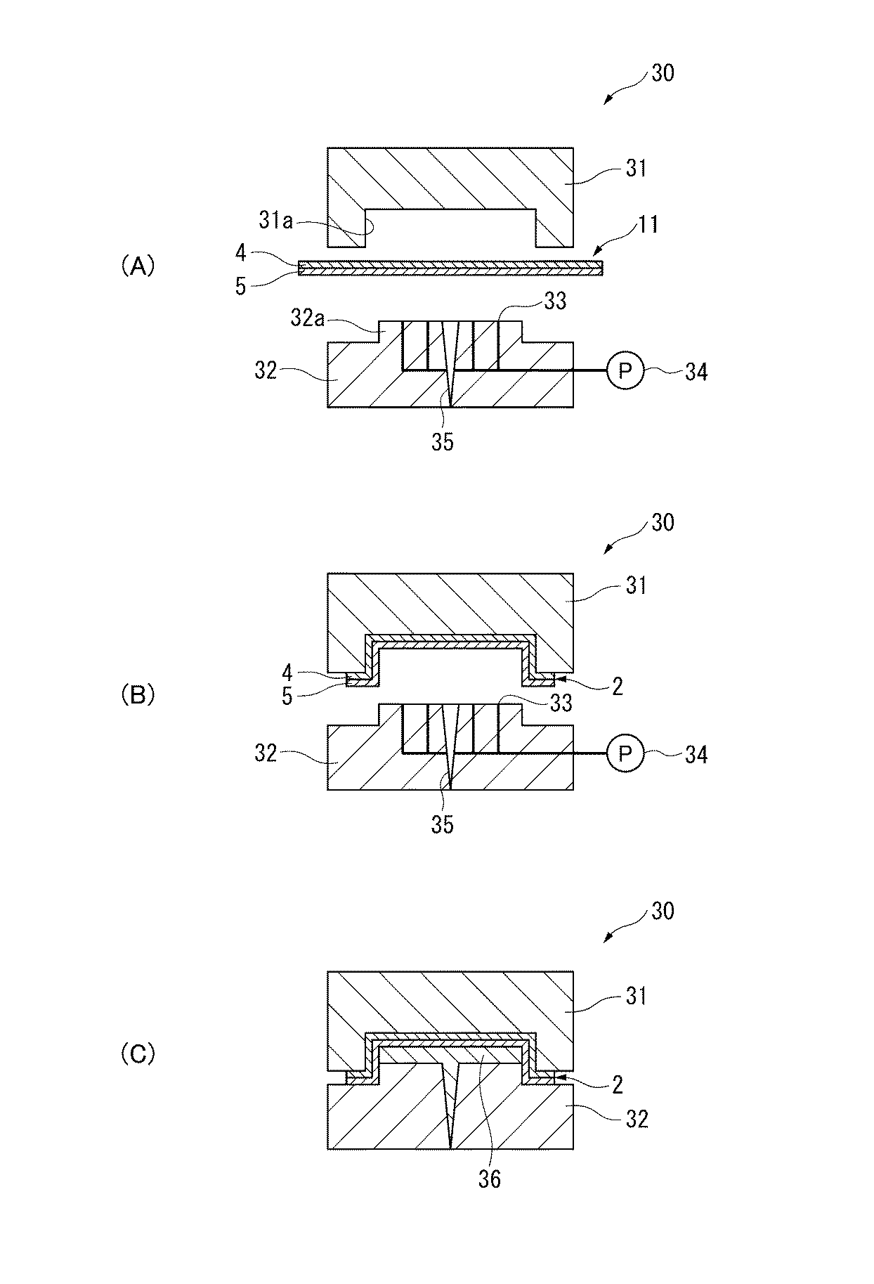
表1から明らかなように、基材層のみから構成された、溶着層が形成されていない透明成型体を用いた比較例1では、密着性に劣る結果が得られた。
一方、実施例1〜4では、密着性に優れていることが確認された。この結果から、透明成型体が基材層および溶着層の2層から形成されていることで、射出成型体との密着性に優れた複合成型体が得られることが判った。
また、透明成型体の基材層および溶着層の双方に、急冷法により得られた透明ポリプロピレンからなる層を用いた実施例1〜3では、白化が生じておらず、複雑な形状の成形に優れることが判った。
As is clear from Table 1, in Comparative Example 1 using a transparent molded body composed of only the base material layer and having no welded layer formed, results of poor adhesion were obtained.
On the other hand, in Examples 1-4, it was confirmed that it is excellent in adhesiveness. From this result, it was found that a composite molded body having excellent adhesion to the injection molded body can be obtained by forming the transparent molded body from two layers of the base material layer and the welded layer.
Moreover, in Examples 1-3 using the layer which consists of a transparent polypropylene obtained by the rapid cooling method in both the base material layer and the welding layer of a transparent molded object, whitening has not arisen and it is in the shaping | molding of a complicated shape. It turned out to be excellent.
1…複合成型体、2…透明成型体、3…射出成型体、4…基材層、4b…印刷面、5…溶着層、10…透明積層シートの製造装置、11…透明積層シート、11a…シート状物、12…Tダイ、13…第1冷却ロール、14…第2冷却ロール、15…第3冷却ロール、16…第4冷却ロール、17…エンドレスベルト、18…冷却水吹き付けノズル、19…水槽、20…吸水ロール、21…剥離ロール、22…弾性材、31…可動側金型、32…固定側金型、33…空気吹き出し孔、34…送気ポンプ、35…ゲート、36…射出成形材料。
DESCRIPTION OF SYMBOLS 1 ... Composite molded object, 2 ... Transparent molded object, 3 ... Injection molded object, 4 ... Base material layer, 4b ... Printing surface, 5 ... Welding layer, 10 ... Transparent laminated sheet manufacturing apparatus, 11 ... Transparent laminated sheet, 11a ... sheet-like material, 12 ... T die, 13 ... first cooling roll, 14 ... second cooling roll, 15 ... third cooling roll, 16 ... fourth cooling roll, 17 ... endless belt, 18 ... cooling water spray nozzle, DESCRIPTION OF
Claims (11)
射出成形により得られた射出成型体と、
を備え、
前記基材層のポリプロピレンは、示差走査型熱量分析(Differential Scanning Calorimetry:DSC)にて測定した融解エンタルピー(ΔH)が60J/g以上200J/g以下であり、
前記溶着層のポリプロピレンは、前記融解エンタルピー(ΔH)が10J/g以上55J/g以下であり、
前記透明成型体と前記射出成型体とが前記溶着層を介して接合されてなる
ことを特徴とする複合成型体。 A transparent molded body composed of at least two layers of a base material layer made of polypropylene and a weld layer made of polypropylene;
An injection molded body obtained by injection molding;
With
The polypropylene of the base material layer has a melting enthalpy (ΔH) measured by differential scanning calorimetry (DSC) of 60 J / g or more and 200 J / g or less,
The polypropylene of the welding layer has a melting enthalpy (ΔH) of 10 J / g or more and 55 J / g or less,
The composite molded body, wherein the transparent molded body and the injection molded body are joined via the weld layer.
前記基材層のポリプロピレンは、アイソタクチックペンタッド分率が80%以上であり、前記溶着層のポリプロピレンは、アイソタクチックペンタッド分率が10%以上75%以下である The base layer polypropylene has an isotactic pentad fraction of 80% or more, and the weld layer polypropylene has an isotactic pentad fraction of 10% to 75%.
ことを特徴とする複合成型体。 A composite molded body characterized by that.
射出成形により得られた射出成型体と、
を備え、
前記基材層のポリプロピレンは、アイソタクチックペンタッド分率が80%以上であり、
前記溶着層のポリプロピレンは、アイソタクチックペンタッド分率が10%以上75%以下であり、
前記透明成型体と前記射出成型体とが前記溶着層を介して接合されてなる
ことを特徴とする複合成型体。 A transparent molded body composed of at least two layers of a base material layer made of polypropylene and a weld layer made of polypropylene;
An injection molded body obtained by injection molding;
With
The base layer polypropylene has an isotactic pentad fraction of 80% or more,
The weld layer polypropylene has an isotactic pentad fraction of 10% to 75%,
The composite molded body, wherein the transparent molded body and the injection molded body are joined via the weld layer.
前記基材層のポリプロピレンは、示差走査型熱量分析(Differential Scanning Calorimetry:DSC)にて測定した融解エンタルピー(ΔH)が60J/g以上200J/g以下であり、前記溶着層のポリプロピレンは、前記融解エンタルピー(ΔH)が10J/g以上55J/g以下である
ことを特徴とする複合成型体。 In the composite molded body according to claim 3 ,
The polypropylene of the base layer has a melting enthalpy (ΔH) measured by differential scanning calorimetry (DSC) of 60 J / g or more and 200 J / g or less. The enthalpy (ΔH) is 10 J / g or more and 55 J / g or less.
前記透明成型体は、平均球晶半径4μm以下、断面の平均球晶数600個/mm2以下、固体密度0.896g/cm3以下、少なくとも片面の光沢が90%以上、かつ厚さが50μm以上の透明積層シートが成形されたものである
ことを特徴とする複合成型体。 In the composite molded body according to any one of claims 1 to 4 ,
The transparent molded body has an average spherulite radius of 4 μm or less, an average number of spherulites in a cross section of 600 / mm 2 or less, a solid density of 0.896 g / cm 3 or less, a gloss of at least one side of 90% or more, and a thickness of 50 μm. A composite molded body characterized in that the above transparent laminated sheet is molded.
前記透明成型体における前記基材層に対する前記溶着層の厚み比(溶着層の厚み/基材層の厚み)が、1/1999以上3/4以下である
ことを特徴とする複合成型体。 In the composite molded body according to any one of claims 1 to 4 ,
The composite molded body, wherein a thickness ratio of the weld layer to the base material layer in the transparent molded body (thickness of the weld layer / thickness of the base material layer) is 1/1999 or more and 3/4 or less.
前記溶着層のポリプロピレンがランダムポリプロピレンであるとき、エチレン含量が1質量%以上15質量%以下である
ことを特徴とする複合成型体。 In the composite molded body according to any one of claims 1 to 6 ,
When the polypropylene of the welding layer is random polypropylene, the ethylene content is 1% by mass or more and 15% by mass or less.
前記基材層のポリプロピレンは、メルトフローレート(MFR)が0.1g/10分以上50g/10分以下であり、前記溶着層のポリプロピレンは、メルトフローレート(MFR)が0.1g/10分以上50g/10分以下である
ことを特徴とする複合成型体。 In the composite molded body according to any one of claims 1 to 7 ,
The polypropylene of the base material layer has a melt flow rate (MFR) of 0.1 g / 10 min or more and 50 g / 10 min or less, and the polypropylene of the weld layer has a melt flow rate (MFR) of 0.1 g / 10 min. More than 50g / 10min. The composite molded object characterized by the above-mentioned.
前記基材層の前記溶着層側の面とは反対の面が印刷面である
ことを特徴とする複合成型体。 In the composite molded body according to any one of claims 1 to 8 ,
The composite molded body, wherein a surface opposite to the surface on the weld layer side of the base material layer is a printing surface.
前記透明成型体は、非平面状に成形される前の表面積Xに対して、非平面状に成形された後の表面積Yの大きさの割合(Y/X)が、1.5以上10以下である
ことを特徴とする複合成型体。 In the composite molded body according to any one of claims 1 to 9 ,
In the transparent molded body, the ratio (Y / X) of the size of the surface area Y after being formed non-planar to the surface area X before being formed non-planar is 1.5 or more and 10 or less. A composite molded body characterized by
前記透明成型体が、非平面状に成形される前の厚さ寸法Aに対して、非平面状に成形された後の厚さ寸法Bの膜厚比(B/A)が、0.8以下に成形された部位を少なくとも一箇所以上有して成形された
ことを特徴とする複合成型体。 In the composite molded body according to any one of claims 1 to 10 ,
The film thickness ratio (B / A) of the thickness dimension B after the non-planar molding is 0.8 to the thickness dimension A before the non-planar molding of the transparent molded body is 0.8. A composite molded body characterized by having at least one or more of the following molded parts.
Priority Applications (1)
| Application Number | Priority Date | Filing Date | Title |
|---|---|---|---|
| JP2013074739A JP6242580B2 (en) | 2013-03-29 | 2013-03-29 | Composite molded body |
Applications Claiming Priority (1)
| Application Number | Priority Date | Filing Date | Title |
|---|---|---|---|
| JP2013074739A JP6242580B2 (en) | 2013-03-29 | 2013-03-29 | Composite molded body |
Publications (2)
| Publication Number | Publication Date |
|---|---|
| JP2014198415A JP2014198415A (en) | 2014-10-23 |
| JP6242580B2 true JP6242580B2 (en) | 2017-12-06 |
Family
ID=52355662
Family Applications (1)
| Application Number | Title | Priority Date | Filing Date |
|---|---|---|---|
| JP2013074739A Active JP6242580B2 (en) | 2013-03-29 | 2013-03-29 | Composite molded body |
Country Status (1)
| Country | Link |
|---|---|
| JP (1) | JP6242580B2 (en) |
Families Citing this family (15)
| Publication number | Priority date | Publication date | Assignee | Title |
|---|---|---|---|---|
| JP6708426B2 (en) * | 2015-02-16 | 2020-06-10 | グンゼ株式会社 | Substrate film for transfer decoration |
| JP6917689B2 (en) * | 2015-09-29 | 2021-08-11 | ダイヤプラスフィルム株式会社 | Decorative sheet and laminated sheet for decoration |
| JP6855957B2 (en) * | 2016-06-30 | 2021-04-07 | 日本ポリプロ株式会社 | A decorative film and a method for manufacturing a decorative molded product using the decorative film. |
| JP6855956B2 (en) * | 2016-07-13 | 2021-04-07 | 日本ポリプロ株式会社 | A decorative film and a method for manufacturing a decorative molded product using the decorative film. |
| WO2018025940A1 (en) * | 2016-08-02 | 2018-02-08 | 日本ポリプロ株式会社 | Decorative film and method for producing decorative molded body using same |
| JP7000715B2 (en) * | 2016-08-02 | 2022-01-19 | 日本ポリプロ株式会社 | A method for manufacturing a decorative film and a decorative molded product using the decorative film. |
| JP6943044B2 (en) * | 2016-08-02 | 2021-09-29 | 日本ポリプロ株式会社 | A decorative film and a method for manufacturing a decorative molded product using the decorative film. |
| JP6965629B2 (en) * | 2016-12-08 | 2021-11-10 | 日本ポリプロ株式会社 | A decorative film and a method for manufacturing a decorative molded product using the decorative film. |
| JP6863174B2 (en) * | 2016-12-08 | 2021-04-21 | 日本ポリプロ株式会社 | A decorative film and a method for manufacturing a decorative molded product using the decorative film. |
| JP6965631B2 (en) * | 2016-12-13 | 2021-11-10 | 日本ポリプロ株式会社 | Decorative film |
| CN110290922A (en) * | 2017-02-14 | 2019-09-27 | 出光统一科技株式会社 | Laminated body, shaped body and method for producing shaped body |
| JP6962064B2 (en) * | 2017-03-15 | 2021-11-05 | 日本ポリプロ株式会社 | A decorative film and a method for manufacturing a decorative molded product using the decorative film. |
| US20200276796A1 (en) * | 2017-09-12 | 2020-09-03 | Idemitsu Unitech Co.,Ltd. | Laminate, molded article, and method for producing molded article |
| EP3715092A4 (en) * | 2017-11-20 | 2021-08-11 | Japan Polypropylene Corporation | DECORATIVE FILM AND METHOD FOR MANUFACTURING A DECORATIVE MOLDED BODY WITH IT |
| DE102018214238B3 (en) | 2018-08-23 | 2019-10-24 | BSH Hausgeräte GmbH | Decorative part for a water-conducting domestic appliance and water-conducting household appliance |
Family Cites Families (7)
| Publication number | Priority date | Publication date | Assignee | Title |
|---|---|---|---|---|
| JPS63149149A (en) * | 1986-12-15 | 1988-06-21 | 東レ株式会社 | Thermal adhesive biaxial-oriented polypropylene film |
| JP3209232B2 (en) * | 1991-09-19 | 2001-09-17 | 凸版印刷株式会社 | Method for manufacturing multilayer thin-walled container |
| JP2965973B1 (en) * | 1998-03-13 | 1999-10-18 | 日本写真印刷株式会社 | Sheet for simultaneous simultaneous painting and method for producing resin molded article with simultaneous simultaneous painting using the same |
| JP2003200537A (en) * | 2001-10-25 | 2003-07-15 | Toray Ind Inc | Film for heat fusion print lamination and print laminate |
| JP5424547B2 (en) * | 2007-09-28 | 2014-02-26 | 三井化学株式会社 | In-mold label and molded product using the same |
| WO2011046126A1 (en) * | 2009-10-14 | 2011-04-21 | 株式会社ユポ・コーポレーション | Label for in-mold molding, in-mold molded article and method for molding same |
| JP5544876B2 (en) * | 2009-12-25 | 2014-07-09 | 東ソー株式会社 | Optical compensation film |
-
2013
- 2013-03-29 JP JP2013074739A patent/JP6242580B2/en active Active
Also Published As
| Publication number | Publication date |
|---|---|
| JP2014198415A (en) | 2014-10-23 |
Similar Documents
| Publication | Publication Date | Title |
|---|---|---|
| JP6242580B2 (en) | Composite molded body | |
| JP3734587B2 (en) | Polypropylene resin outer plate and method for producing the same | |
| JP6837453B2 (en) | Laminated body, molded body using the laminated body and its manufacturing method | |
| JP6037920B2 (en) | Molded product for decorative use and method for producing the same | |
| CN105102226B (en) | Layered product, formed body, the manufacture method of molding and molding | |
| JP6779095B2 (en) | Manufacturing method of shaping decorative sheet | |
| JP6037919B2 (en) | LAMINATE, MOLDED BODY, MOLDED BODY, AND METHOD FOR PRODUCING MOLDED BODY | |
| JP6870525B2 (en) | A decorative film and a method for manufacturing a decorative molded product using the decorative film. | |
| JP6963392B2 (en) | Laminated body, molded body and manufacturing method of molded body | |
| JP4335073B2 (en) | LAMINATED SHEET MANUFACTURING METHOD, LAMINATED SHEET, AND MOLDED ARTICLE | |
| JP2021181232A (en) | Manufacturing method of decorative molded product | |
| JP6969176B2 (en) | Decorative film and decorative molded body using it | |
| JP2016141745A (en) | Resin sheet, molded product, resin sheet manufacturing method, and molded product manufacturing method | |
| JP2022043256A (en) | A method for manufacturing a resin composition for a decorative film, a decorative film, and a decorative molded product. | |
| JP6950340B2 (en) | A decorative film and a method for manufacturing a decorative molded product using the decorative film. | |
| JP7513075B2 (en) | Resin composition for decorative film and decorative film using same | |
| JP3599838B2 (en) | Method for manufacturing multilayer products | |
| JP2018154109A (en) | Decorative film and method for producing decorative molding using the same | |
| JP5017002B2 (en) | Multilayer blow molded article and method for producing the same | |
| JP6962064B2 (en) | A decorative film and a method for manufacturing a decorative molded product using the decorative film. | |
| JPH08207145A (en) | Multilayered article and manufacture thereof |
Legal Events
| Date | Code | Title | Description |
|---|---|---|---|
| A621 | Written request for application examination |
Free format text: JAPANESE INTERMEDIATE CODE: A621 Effective date: 20151210 |
|
| A977 | Report on retrieval |
Free format text: JAPANESE INTERMEDIATE CODE: A971007 Effective date: 20161006 |
|
| A131 | Notification of reasons for refusal |
Free format text: JAPANESE INTERMEDIATE CODE: A131 Effective date: 20161018 |
|
| A521 | Written amendment |
Free format text: JAPANESE INTERMEDIATE CODE: A523 Effective date: 20161216 |
|
| A131 | Notification of reasons for refusal |
Free format text: JAPANESE INTERMEDIATE CODE: A131 Effective date: 20170411 |
|
| A521 | Written amendment |
Free format text: JAPANESE INTERMEDIATE CODE: A523 Effective date: 20170609 |
|
| A02 | Decision of refusal |
Free format text: JAPANESE INTERMEDIATE CODE: A02 Effective date: 20170704 |
|
| A521 | Written amendment |
Free format text: JAPANESE INTERMEDIATE CODE: A523 Effective date: 20170925 |
|
| A911 | Transfer of reconsideration by examiner before appeal (zenchi) |
Free format text: JAPANESE INTERMEDIATE CODE: A911 Effective date: 20171003 |
|
| TRDD | Decision of grant or rejection written | ||
| A01 | Written decision to grant a patent or to grant a registration (utility model) |
Free format text: JAPANESE INTERMEDIATE CODE: A01 Effective date: 20171031 |
|
| A61 | First payment of annual fees (during grant procedure) |
Free format text: JAPANESE INTERMEDIATE CODE: A61 Effective date: 20171108 |
|
| R150 | Certificate of patent or registration of utility model |
Ref document number: 6242580 Country of ref document: JP Free format text: JAPANESE INTERMEDIATE CODE: R150 |