JP6281966B1 - Eye drop device - Google Patents
Eye drop device Download PDFInfo
- Publication number
- JP6281966B1 JP6281966B1 JP2017102166A JP2017102166A JP6281966B1 JP 6281966 B1 JP6281966 B1 JP 6281966B1 JP 2017102166 A JP2017102166 A JP 2017102166A JP 2017102166 A JP2017102166 A JP 2017102166A JP 6281966 B1 JP6281966 B1 JP 6281966B1
- Authority
- JP
- Japan
- Prior art keywords
- eye drop
- injection mechanism
- chemical
- eye
- chemical solution
- Prior art date
- Legal status (The legal status is an assumption and is not a legal conclusion. Google has not performed a legal analysis and makes no representation as to the accuracy of the status listed.)
- Expired - Fee Related
Links
Images


Landscapes
- Medical Preparation Storing Or Oral Administration Devices (AREA)
Abstract
【課題】適量の薬液を的確に眼球の薬液投与部に射出し、使用者が簡易に扱える点眼装置を提供する。
【解決手段】薬液が収容された容器が配置される配置部、前記薬液を水平方向に射出する射出機構、駆動信号を前記射出機構に出力する制御部と、前記配置部、前記射出機構及び前記制御部を内部に収容する筐体とを具備する点眼装置であって、前記筐体は、前記制御部を操作するための操作スイッチと、被検体の眼窩口縁に沿って密接させるための筒状の先端縁部と、当該筒状の先端縁部の中央に形成された薬液射出口とを有する筒状部とを備え、前記筒状部の先端縁部が、目を開いた前記被検体の眼窩口縁に沿って密接されるとき、前記筒状部の先端縁部が前記被検体の上瞼並びに下瞼を押さえ目が閉じられるのを抑制し、前記薬液射出口が、眼球の薬液投与部に正対するように位置することを特徴とする点眼装置
【選択図】 図1An eye drop device that accurately ejects an appropriate amount of drug solution to a drug solution administration portion of an eyeball and that can be easily handled by a user.
An arrangement unit in which a container containing a chemical solution is arranged, an injection mechanism that injects the chemical solution in a horizontal direction, a control unit that outputs a drive signal to the injection mechanism, the arrangement unit, the injection mechanism, and the An ophthalmic apparatus comprising a housing for accommodating a control unit therein, wherein the housing is configured to be in close contact with an operation switch for operating the control unit and an orbital lip of the subject. And a cylindrical portion having a cylindrical tip edge portion and a chemical solution injection port formed at the center of the cylindrical tip edge portion, and the tip edge portion of the cylindrical portion has the eye open. When the eyeball is closely in contact with the orbital lip of the eye, the tip edge of the cylindrical portion holds the upper and lower eyelids of the subject to suppress closing of the eye, and the liquid medicine injection port is a liquid medicine for the eyeball. An ophthalmic device characterized by being positioned so as to face the administration part.
Description
本発明は、眼に液体を投与するための点眼装置に関する。 The present invention relates to an eye drop device for administering a liquid to the eye.
多くの眼科の医学症状は、薬液を眼に投与することにより効果的に処置することができる。このような薬液の例としては、緑内障処置用のβ遮断薬、又はプロスタグランジン製剤、角膜感染処置用の抗生物質、眼球乾燥症(ドライアイ)処置用の人工涙液がある。眼に薬液を投与することで所望の治療効果を得るためには、薬液を定期的かつ規則的に投与することが必要である。 Many ophthalmic medical conditions can be effectively treated by administering a drug solution to the eye. Examples of such chemical solutions include β-blockers for glaucoma treatment, or prostaglandin preparations, antibiotics for treatment of corneal infection, and artificial tears for treatment of dry eye (dry eye). In order to obtain a desired therapeutic effect by administering a drug solution to the eye, it is necessary to administer the drug solution regularly and regularly.
眼科領域において使用される治療薬の多くは液状の薬液である。よって従来の点眼は、薬液の入った容器の先端に設けられたノズルから眼球表面に向けて薬液を滴下する方法が用いられる。しかし当該方法は、顔を上に向けて滴下することに伴う操作の煩雑性によって、患者が点眼を怠るという問題点を有する。また、当該方法は薬液の容器に圧力をかけて、該圧力によって容器から薬液を押し出し滴下し投与することから、毎回同じ量で薬液を投与できないという問題点を有する。さらに、患者毎に容器にかける圧力の加減が異なるため、決められた量の薬液を投与することは難しく、市販されている容器入りの薬液では1滴あたり約30〜50μlと投与量に差が出るという問題点も有する。このように眼科領域の薬液投与においては、経口投与のように患者毎に毎回同じ量の薬液を投与することは困難であった。 Many of the therapeutic agents used in the ophthalmic field are liquid drug solutions. Therefore, the conventional eye drop uses a method in which the chemical solution is dropped from the nozzle provided at the tip of the container containing the chemical solution toward the eyeball surface. However, this method has a problem in that the patient neglects instillation due to the complexity of the operation associated with dripping the face upward. In addition, this method has a problem in that the chemical solution cannot be administered in the same amount each time because the chemical solution is pressurized and the chemical solution is pushed out and dropped from the container by the pressure. Furthermore, since the pressure applied to the container varies from patient to patient, it is difficult to administer a predetermined amount of the drug solution, and there is a difference in the dose of about 30-50 μl per drop with a commercially available drug solution in a container. It also has the problem of coming out. As described above, in the administration of drug solutions in the ophthalmic field, it is difficult to administer the same amount of drug solution for each patient as in oral administration.
さらに、例えば緑内障の薬液は高価であるが、約20μlの滴下においても効果があるところ、上述のように従来の薬液の滴下による投与方法では過剰量の薬液が投与されるという問題点があった。また過剰投与された薬液は眼球表面に保持されることなく鼻涙管を通って体内に吸収されて不適切な生理現象を引き起こしたり、眼から溢れ出た薬液は身体の不具合を引き起こす。例えば、プロスタグランジン製剤を使用する場合、眼から溢れ出た薬液によって眼の周辺に黒い色素沈着が起こるなどの問題点があった。 Further, for example, although a glaucoma drug solution is expensive, it is effective even when about 20 μl is dropped. However, as described above, there is a problem that an excessive amount of drug solution is administered by the conventional method of dropping a drug solution. . In addition, an over-administered drug solution is absorbed into the body through the nasolacrimal duct without being held on the surface of the eyeball, causing an inappropriate physiological phenomenon, or a drug solution overflowing from the eye causes a physical malfunction. For example, when a prostaglandin preparation is used, there is a problem that black pigmentation occurs around the eye due to a chemical solution overflowing from the eye.
また瞼を有する生物は、眼瞼反射と呼ばれる反応によって眼の近くに物体が急に近づくと反射的に瞼を閉じる習性を持つ。該眼瞼反射によって、眼球に滴下投与された薬液に反応し瞼を閉じてしまうため、的確に薬液を眼球に投与できないという問題点があった。 Living creatures with eyelids have a habit of closing the eyelids reflexively when an object suddenly approaches the eye due to a reaction called eyelid reflex. Since the eyelid reflex causes the eyelid to close in response to the drug solution dropped onto the eyeball, there is a problem that the drug solution cannot be accurately administered to the eyeball.
そこで、上述の薬液の滴下投与する方法の問題を解決するために、装置を用いて薬液の投与を制御する方法がある。 Therefore, in order to solve the above-described problem of the method of administering the drug solution dropwise, there is a method of controlling the administration of the drug solution using an apparatus.
例えば、特許文献1には点眼薬を眼球に投与するための装置として、患者自身が簡便に使用できる小型の装置が開示されている。しかしながら、特許文献1には供給ノズルを有する液体用容器、投与チャンバ及び液体放出に関する機構について開示されているが、作動機構から放出される液量を使用毎に制御し調整することは教示されていない。 For example, Patent Document 1 discloses a small device that can be easily used by a patient as an apparatus for administering eye drops to an eyeball. However, although Patent Document 1 discloses a liquid container having a supply nozzle, a dosing chamber, and a mechanism related to liquid discharge, it teaches that the amount of liquid discharged from an operating mechanism is controlled and adjusted for each use. Absent.
一方、特許文献2及び特許文献3には、フレーム部分に薬液投与部を備えた眼鏡型の装置が開示されている。特許文献2には、瞼の開閉を検知するセンサーが開示されているが、眼鏡型であるため使用者毎に装置の調整が必要である。一方特許文献3に記載された発明は、眼が投与位置にあるか検出する眼位置合わせデバイスを備えているが、コントローラやコンピューティング装置など多様で大掛かりな装置を必要とし、簡易に使用できるものではない。 On the other hand, Patent Document 2 and Patent Document 3 disclose spectacle-type devices having a chemical liquid administration section in a frame portion. Patent Document 2 discloses a sensor that detects opening and closing of a bag, but since it is a glasses type, adjustment of the device is required for each user. On the other hand, the invention described in Patent Document 3 includes an eye alignment device that detects whether the eye is at the administration position, but requires various and large-scale devices such as a controller and a computing device and can be used easily. is not.
また、特許文献4には、眼薬噴霧供給装置が開示されている。該眼薬噴霧供給装置は超音波メッシュ式霧化機構によって極微小量の眼薬を投与し、眼球表面に沈着させるというものである。特許文献5にもミスト又はスプレーの形態で流体を投与する噴霧装置が開示されている。これらの装置は極微小量の眼薬を投与できるが、眼薬が霧化しているため眼球表面に投与されるだけでなく、眼の周辺の皮膚に付着する可能性がある。 Patent Document 4 discloses an ophthalmic spray supply device. The ophthalmic spray supply device administers an extremely small amount of ophthalmic drug by an ultrasonic mesh atomizing mechanism and deposits it on the surface of the eyeball. Patent Document 5 also discloses a spray device that administers fluid in the form of mist or spray. Although these devices can administer very small amounts of eye drops, they are not only administered to the surface of the eyeball due to the atomization of the eye drops, but may adhere to the skin around the eyes.
上述するように、従来の点眼装置では、薬液の射出に関する設計や使用者が使いやすい構造に関する設計について、未だ課題が残っている。したがって、使用者にとって使いやすく、的確に薬液を射出する点眼装置が求められている。 As described above, in the conventional eye drop device, problems still remain with respect to the design related to the injection of the chemical liquid and the design related to the structure that is easy for the user to use. Therefore, there is a need for an eye drop device that is easy for the user to use and that accurately injects a chemical solution.
そこで、本発明の点眼装置は上記した問題点を解決すべくなされたものであり、適量の薬液を的確に眼球の薬液投与部に射出し、簡易に扱える点眼装置を提供する。 Therefore, the eye drop device of the present invention has been made to solve the above-mentioned problems, and provides an eye drop device that can easily handle an appropriate amount of a drug solution by accurately injecting it into a drug solution administration part of an eyeball.
請求項1に係る発明は、
薬液が収容された容器が配置される配置部と、
前記容器と連結され前記容器内の前記薬液を水平方向に射出する射出機構と、
前記射出機構を駆動させる駆動信号を前記射出機構に出力する制御部と、
前記配置部、前記射出機構及び前記制御部を内部に収容する筐体とを具備する点眼装置であって、
前記筐体は、前記制御部を操作するための操作スイッチと、
被検体の眼窩口縁に沿って密接させるための筒状の先端縁部を有する筒状部と、
前記筒状の先端縁部の中央に貫通孔と薬液射出口を有するノズルとを備え、
前記筒状部の先端縁部が、目を開いた前記被検体の眼窩口縁に沿って密接されるとき、前記筒状部の先端縁部が前記被検体の上瞼並びに下瞼を押さえ目が閉じられるのを抑制し、前記薬液射出口が、眼球の薬液投与部に正対するように位置し、
前記駆動信号は、パルス信号であり、
前記操作スイッチの操作により、パルス幅及び/又はパルス間隔が調整されたパルス信号が前記制御部から出力され、
前記射出機構は、パルス幅及び/又はパルス間隔の調整によって単回駆動で必要最低量を瞬間的に射出できる圧電マイクロポンプであり、
前記ノズルは、前記圧電マイクロポンプの吐出口に連結され、
前記貫通孔の長さは1.0mm〜3.0mmであり、
前記薬液射出口の直径は0.1mm〜0.3mmであり、
治療のための薬液を常に設定量投与することができることを特徴とする点眼装置に関する。
The invention according to claim 1
An arrangement part in which a container containing a chemical solution is arranged;
An injection mechanism that is connected to the container and injects the chemical in the container in a horizontal direction;
A control unit for outputting a drive signal for driving the injection mechanism to the injection mechanism;
An eye drop device comprising a housing that houses the arrangement unit, the injection mechanism, and the control unit,
The housing includes an operation switch for operating the control unit;
A cylindrical part having a cylindrical tip edge part to be brought into close contact with the orbital lip of the subject ;
A nozzle having a through-hole and a chemical injection port at the center of the cylindrical tip edge ,
When the distal edge of the cylindrical portion is brought into close contact with the orbital lip of the subject whose eyes are open, the distal edge of the tubular portion holds the upper and lower eyelids of the subject. Is closed, and the drug solution injection port is positioned to face the drug solution administration part of the eyeball,
The drive signal is a pulse signal;
By operating the operation switch, a pulse signal whose pulse width and / or pulse interval is adjusted is output from the control unit,
The injection mechanism is a piezoelectric micropump that can instantaneously inject the required minimum amount by a single drive by adjusting the pulse width and / or pulse interval,
The nozzle is connected to a discharge port of the piezoelectric micropump,
The length of the through hole is 1.0 mm to 3.0 mm,
The diameter of the chemical injection port is 0.1 mm to 0.3 mm,
The present invention relates to an eye drop device characterized by being able to always administer a predetermined amount of a medical solution for treatment.
請求項2に係る発明は、
前記射出機構は、前記操作スイッチは複数設けられ、夫々の前記操作スイッチの操作によって、異なるパルス幅を有するパルス信号を出力することを特徴とする請求項1に記載の点眼装置に関する。
The invention according to claim 2
The ophthalmic device according to claim 1, wherein the ejection mechanism is provided with a plurality of the operation switches, and outputs a pulse signal having a different pulse width according to an operation of each of the operation switches .
請求項3に係る発明は、
前記容器から前記射出機構に薬液を供給するための薬液供給管を備え、前記薬液供給管が前記容器及び前記射出機構と独立して取付け取外し可能であること特徴とする請求項1または3に記載の点眼装置に関する。
The invention according to claim 3
It includes a chemical liquid supply pipe for supplying a chemical liquid to the injection mechanism from the container, according to claim 1 or 3, wherein said chemical liquid supply pipe is attachable removable independently of the container and the injection mechanism It is related with the eye drop apparatus.
請求項4に係る発明は、
前記薬液射出口を開閉する抗菌性シャッターが設置されていることを特徴とする請求項1乃至3のいずれか1項に記載の点眼装置に関する。
The invention according to claim 4
The ophthalmic apparatus according to any one of claims 1 to 3, wherein an antibacterial shutter that opens and closes the chemical liquid ejection port is provided.
請求項5に係る発明は、
前記薬液射出口で脱着可能なキャップを有し、前記キャップは抗菌剤を含有した保湿用キャップであることを特徴とする、請求項1乃至4のいずれか1項に記載の点眼装置に関する。
The invention according to claim 5
It has removable cap by the chemical injection port, wherein the cap is a cap for moisturizing containing an antimicrobial agent, regarding ophthalmic apparatus according to any one of claims 1 to 4.
請求項6に係る発明は、
前記被検体が動物であることを特徴とする、請求項1乃至5のいずれか1項に記載の点眼装置に関する。
The invention according to claim 6
Wherein the subject is an animal, to ophthalmic apparatus according to any one of claims 1 to 5.
薬液を水平方向に射出する射出機構、前記射出機構を駆動させる駆動信号を前記射出機構に出力する制御部、筒状部の先端縁部が被検体の上瞼並びに下瞼を押さえ目が閉じられるのを抑制し、薬液射出口が、眼球の薬液投与部に正対するように位置することを特徴とする点眼装置は、被検体である使用者が薬液を眼球に投与する際に上を向く必要がなく、眼球の投与部分に薬液を的確に投与することができる。
また、パルス幅やパルス間隔が調整されたパルス信号が出力される点眼装置によれば、多様で大掛かりな装置を備えることなく、治療のための薬液を適量(常に設定量)投与することができるため、使用者は、簡易に本発明の点眼装置を扱うことができる。
さらに、薬液供給管が取付け取外し可能となったり、抗菌性を有するキャップやシャッターを備えたりする点眼装置によれば、細菌に汚染されることを防止することができ、無菌性を担保することができる。
An injection mechanism for injecting a chemical solution in the horizontal direction, a control unit for outputting a drive signal for driving the injection mechanism to the injection mechanism, and a tip edge of the cylindrical portion pressing the upper and lower eyelids of the subject to close the eyes The eye drop device is characterized in that the medical solution injection port is positioned so as to face the medical solution administration portion of the eyeball, and the user who is the subject needs to face upward when administering the chemical solution to the eyeball. Therefore, the drug solution can be accurately administered to the administration part of the eyeball.
In addition, according to the eye drop device that outputs a pulse signal whose pulse width and pulse interval are adjusted, it is possible to administer an appropriate amount (always set amount) of a medical solution for treatment without providing various and large-scale devices. Therefore, the user can easily handle the eye drop device of the present invention.
Furthermore, according to the eye drop device in which the chemical solution supply pipe can be attached and detached, or provided with an antibacterial cap or shutter, it can be prevented from being contaminated with bacteria, and sterility can be ensured. it can.
以下に、本発明の実施形態について図面に基づいて説明する。 Embodiments of the present invention will be described below with reference to the drawings.
<第一実施形態>
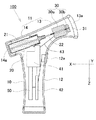
図1は、本発明の実施形態に係る点眼装置の一例を示す縦断面図であり、図2は、点眼装置の使用状態の一例を示す斜視図である。なお、X方向を前方方向とし、Y方向を左右方向とし、Z方向を鉛直方向とする。
<First embodiment>
FIG. 1 is a longitudinal sectional view showing an example of an eye drop device according to an embodiment of the present invention, and FIG. 2 is a perspective view showing an example of a usage state of the eye drop device. The X direction is the forward direction, the Y direction is the left-right direction, and the Z direction is the vertical direction.
点眼装置(100)は、側面視で略T字形状の筐体(10)を具備する。そして、詳細は後述するが、筐体(10)内の所定位置には、点眼ボトル(容器)(21)が配置される配置部(20)と、ポンプユニット(射出機構)(30)と、駆動回路(制御部)(41)と、制御回路(制御部)(42)と、駆動回路(41)及び制御回路(42)に電力を供給するボタン電池(電源)(50)とが配置されている。なお、本実施形態では点眼ボトル(21)には、市販されているものが用いられることができ、例えばβ遮断薬、プロスタグランジン製剤等の薬液が収容されたもの等が用いられる。 The eye drop device (100) includes a substantially T-shaped housing (10) in a side view. And although mentioned later for details, the arrangement | positioning part (20) by which an eye drop bottle (container) (21) is arrange | positioned in the predetermined position in a housing | casing (10), a pump unit (injection mechanism) (30), A drive circuit (control unit) (41), a control circuit (control unit) (42), and a button battery (power source) (50) for supplying power to the drive circuit (41) and the control circuit (42) are arranged. ing. In the present embodiment, a commercially available product can be used as the eye drop bottle (21). For example, a product containing a chemical solution such as a β-blocker or a prostaglandin preparation is used.
<筐体(10)の形状(外部構成)>
筐体(10)は、X方向に中心軸を有する円筒状水平部(11)と、円筒状水平部(11)の中央部から下方(Z方向)に延出された円筒状垂直部(12)とを備える。円筒状垂直部(12)は、図2に示すように片手で把持されるようになっており、その外周の所定位置に、制御回路(42)等に入力信号を出力するために指で操作される操作スイッチ(12a)が形成されている。
<Shape (10) Shape (External Configuration)>
The casing (10) includes a cylindrical horizontal portion (11) having a central axis in the X direction and a cylindrical vertical portion (12) extending downward (Z direction) from the central portion of the cylindrical horizontal portion (11). ). The cylindrical vertical portion (12) is grasped with one hand as shown in FIG. 2, and is operated with a finger to output an input signal to the control circuit (42) or the like at a predetermined position on the outer periphery thereof. An operation switch (12a) to be operated is formed.
円筒状水平部(11)は、円環形状の先端フレーム(先端縁部)(13a)を有する前側部(筒状部)(13)と、後側部(14)とを備える。円環形状の先端フレーム(13a)は、ヒトの目の大きさより少し大きくなり、かつ、ゴム等で形成されており、ヒトによってヒトの眼窩口縁に沿って押し当てられることで密接され、薬液射出口(31)がヒトの眼球の薬液投与部に正対する位置に来るように構成されている。 The cylindrical horizontal portion (11) includes a front side portion (cylindrical portion) (13) having an annular tip frame (tip end portion) (13a) and a rear side portion (14). The ring-shaped tip frame (13a) is slightly larger than the size of the human eye and is made of rubber or the like, and is brought into close contact with the human eye by being pressed along the orbital lip of the human eye. The injection port (31) is configured to come to a position facing the drug solution administration part of the human eyeball.
そして、図4に示すように円環形状の先端フレーム(13a)に円形状の保湿用キャップ(13b)が、ヒトによって脱着可能となっている。保湿用キャップ(13b)の材質としては、ポリウレタン、ゴム等が挙げられ、ベンザルコニウム塩化物等の抗菌剤が含有されていることが好ましい。 As shown in FIG. 4, the circular moisturizing cap (13b) can be attached to and detached from the annular tip frame (13a) by a human. Examples of the material of the moisturizing cap (13b) include polyurethane and rubber, and preferably contains an antibacterial agent such as benzalkonium chloride.
このような筐体(10)の形状により、使用者は先端フレーム(13a)から保湿用キャップ(13b)を取り外した後、円筒状垂直部(12)を片手で把持して、前方向(X方向)を向いた状態で先端フレーム(13a)を眼窩口縁に密接させる。このとき、使用者が目を開いた状態で先端フレーム(13a)を眼窩口縁に密接させると、上瞼と下瞼とが先端フレーム(13a)で押さえられ、目が閉じられるのを抑制することができる。 With such a shape of the housing (10), the user removes the moisturizing cap (13b) from the distal end frame (13a), and then grips the cylindrical vertical portion (12) with one hand and moves forward (X The tip frame (13a) is brought into intimate contact with the orbital lip with the direction facing. At this time, when the user closes the tip frame (13a) to the orbital lip with the eyes open, the upper eyelid and the lower eyelid are pressed by the tip frame (13a) and the eyes are prevented from being closed. be able to.
<筐体10の内部構成>
配置部(20)は、後側部(14)内に形成されており、後側部(14)の後端部には円形状の蓋体(14a)が取付け取外し可能となっている。これにより、蓋体(14a)を取り外して、配置部(20)に点眼ボトル(21)が配置されるようになっている。
<Internal configuration of
The arrangement portion (20) is formed in the rear side portion (14), and a circular lid (14a) can be attached to and detached from the rear end portion of the rear side portion (14). Thereby, the lid (14a) is removed, and the eye drop bottle (21) is arranged on the arrangement part (20).
ポンプユニット(30)は、圧電マイクロポンプ(30a)とノズル(30b)とを備え、前側部(13)内に設置されている。
圧電マイクロポンプ(30a)としては、例えば株式会社菊池製作所製の圧電式ダイヤフラム式のメタルマイクロポンプ等が挙げられる。圧電マイクロポンプ(30a)は、例えば、10mm×11mm×2.7mmの直方体のケースを有し、ケースには外径1.2mm、内径0.7mmの吐出口(31a)と吸入口(31b)とが形成されている。そして、圧電マイクロポンプ(30a)のケース内には、駆動回路(41)とケーブル(43)を介して接続された圧電素子(例えばチタン酸ジルコン酸鉛等)と、吐出口(31a)及び吸入口(31b)と連結された液室とを備える。
ノズル(30b)は、中心軸がX方向(水平方向)になるように配置され、中央部に貫通孔(流路)が形成されている。ノズル(30b)の形状としては、四角柱、円柱、略四角柱、略円錐等が挙げられる。貫通孔の入口(31c)が圧電マイクロポンプ(30a)の吐出口(31a)と連結され、貫通孔の出口が薬液射出口(31)となる。薬液射出口(31)は、円環形状の先端フレーム(13a)の中央に位置するように配置されている。上記貫通孔の長さは、眼球の投与部分に薬液を的確に投与する観点から1.0mm以上3.0mm以下であり、上記薬液射出口の直径は、眼球の投与部分に薬液を的確に投与する観点から0.1mm以上0.3mm以下であることが好ましい。
The pump unit (30) includes a piezoelectric micro pump (30a) and a nozzle (30b), and is installed in the front side portion (13).
Examples of the piezoelectric micro pump (30a) include a piezoelectric diaphragm type metal micro pump manufactured by Kikuchi Manufacturing Co., Ltd. The piezoelectric micro pump (30a) has, for example, a rectangular parallelepiped case of 10 mm × 11 mm × 2.7 mm, and the case has a discharge port (31a) and a suction port (31b) having an outer diameter of 1.2 mm and an inner diameter of 0.7 mm. And are formed. In the case of the piezoelectric micropump (30a), the piezoelectric element (for example, lead zirconate titanate) connected to the drive circuit (41) via the cable (43), the discharge port (31a), and the suction port A liquid chamber connected to the mouth (31b).
The nozzle (30b) is arranged so that the central axis is in the X direction (horizontal direction), and a through hole (flow path) is formed in the center. Examples of the shape of the nozzle (30b) include a quadrangular prism, a cylinder, a substantially quadrangular prism, and a substantially cone. The inlet (31c) of the through hole is connected to the discharge port (31a) of the piezoelectric micro pump (30a), and the outlet of the through hole becomes the chemical solution injection port (31). The chemical injection port (31) is disposed so as to be located at the center of the annular tip frame (13a). The length of the through-hole is 1.0 mm or more and 3.0 mm or less from the viewpoint of accurately administering the drug solution to the administration part of the eyeball, and the diameter of the drug solution ejection port accurately administers the drug solution to the administration part of the eyeball It is preferable that it is 0.1 mm or more and 0.3 mm or less from a viewpoint to do.
一方、圧電マイクロポンプ(30a)の吸入口(31b)には、円管状のディスポーサブルチューブ(薬液供給管)(22)の先端部が取付け取外し可能に配置されるとともに、ディスポーサブルチューブ(22)の末端部が点眼ボトル(21)内に配置されている。図3は、圧電マイクロポンプ(30a)とノズル(30b)とディスポーサブルチューブ(22)と点眼ボトル(21)との関係を示す断面図である。上記ディスポーサブルチューブ(22)の直径は、1.0mm以上2.0mm以下であることが好ましい。しかし圧電マイクロポンプ(30a)の吸入口(31b)は、上記ディスポーサブルチューブ(22)を用いることなく直接点眼ボトル(21)と接続してもよい。 On the other hand, a distal end portion of a circular disposable tube (chemical solution supply tube) (22) is detachably disposed at the suction port (31b) of the piezoelectric micropump (30a), and the distal end of the disposable tube (22). The part is arranged in the eye drop bottle (21). FIG. 3 is a cross-sectional view showing the relationship among the piezoelectric micro pump (30a), the nozzle (30b), the disposable tube (22), and the eye drop bottle (21). The diameter of the disposable tube (22) is preferably 1.0 mm or more and 2.0 mm or less. However, the suction port (31b) of the piezoelectric micropump (30a) may be directly connected to the eye drop bottle (21) without using the disposable tube (22).
そして、図3に示すように円形状の薬液射出口(31)の前方に円形状の抗菌性シャッター(32)が設置されている。これにより、抗菌性シャッター(32)が開けられると薬液射出口(31)が解放され、一方、抗菌性シャッター(32)が閉じられると薬液射出口(31)が封鎖されようになっている。上記抗菌性シャッターは、図示しないが駆動機構によって開閉が行われ得る。上記抗菌性シャッター(32)の材質としては、ポリウレタン、ゴム等が挙げられ、ベンザルコニウム塩化物等の抗菌剤が含有されていることが好ましい。 And as shown in FIG. 3, the circular antimicrobial shutter (32) is installed ahead of the circular chemical | medical solution injection port (31). Thereby, when the antibacterial shutter (32) is opened, the chemical liquid ejection port (31) is released, and when the antibacterial shutter (32) is closed, the chemical liquid ejection port (31) is blocked. The antibacterial shutter can be opened and closed by a driving mechanism (not shown). Examples of the material of the antibacterial shutter (32) include polyurethane, rubber, and the like, and preferably contains an antibacterial agent such as benzalkonium chloride.
このようなポンプユニット(30)によれば、駆動回路(41)から圧電素子に駆動信号が出力されると、抗菌性シャッター(32)が開かれるとともに圧電素子が作動して、点眼ボトル(21)内の薬液がディスポーサブルチューブ(22)内に吸い上げられ、そして、薬液が薬液射出口(31)から−X方向(水平方向)に射出される。 According to such a pump unit (30), when a drive signal is output from the drive circuit (41) to the piezoelectric element, the antibacterial shutter (32) is opened and the piezoelectric element is operated, so that the eye drop bottle (21 ) Is sucked into the disposable tube (22), and the chemical liquid is ejected from the chemical liquid ejection port (31) in the -X direction (horizontal direction).
制御回路(42)は、円筒状垂直部(12)内に設置されており、使用者による操作スイッチ(12a)での入力操作に基づいて、制御信号を駆動回路(41)に出力する。例えば、使用者が操作スイッチ(12a)を押圧すると、制御回路(42)は、操作スイッチ(12a)が押圧されたことを示す制御信号を駆動回路(41)に出力する。また、複数の操作スイッチ(12a)を形成しておき、制御回路(42)が、どの操作スイッチ(12a)が押圧されたかを示す制御信号を駆動回路(41)に出力するようにしてもよい。これにより、例えば、「子供」の眼に薬液を投与するための第一の操作スイッチ(12a)が押圧されると、第一のパルス幅Aを有する1個のパルスからなるパルス信号を出力させるための制御信号を駆動回路(41)に出力する。一方、「成人」の眼に薬液を投与するための第二の操作スイッチ(12a)が押圧されると、第二のパルス幅Bを有する1個のパルスからなるパルス信号を出力させるための制御信号を駆動回路(41)に出力する。つまり、投与する対象「子供」「成人」によって異なるパルス幅A、Bを有するパルスからなるパルス信号を出力させるための制御信号を駆動回路(41)に出力することができる。 The control circuit (42) is installed in the cylindrical vertical portion (12), and outputs a control signal to the drive circuit (41) based on an input operation by the user with the operation switch (12a). For example, when the user presses the operation switch (12a), the control circuit (42) outputs a control signal indicating that the operation switch (12a) has been pressed to the drive circuit (41). A plurality of operation switches (12a) may be formed, and the control circuit (42) may output a control signal indicating which operation switch (12a) is pressed to the drive circuit (41). . Thereby, for example, when the first operation switch (12a) for administering the drug solution to the eyes of the “child” is pressed, a pulse signal composed of one pulse having the first pulse width A is output. The control signal is output to the drive circuit (41). On the other hand, when the second operation switch (12a) for administering the drug solution to the “adult” eye is pressed, a control for outputting a pulse signal composed of one pulse having the second pulse width B is performed. The signal is output to the drive circuit (41). That is, a control signal for outputting a pulse signal composed of pulses having different pulse widths A and B depending on the administration target “child” and “adult” can be output to the drive circuit (41).
駆動回路(41)は、プログラマブルパルス発生器やパルス増幅器等を有するものであり、円筒状垂直部(12)内に設置されており、制御回路(42)から入力された制御信号に基づいて、駆動信号として予め設定されたパルス幅を有する設定数のパルスからなるパルス信号をポンプユニット(30)の圧電素子に出力する。例えば、第一のパルス幅Aを有する1個のパルスからなるパルス信号を出力させるための制御信号が入力されると、第一のパルス幅Aを有する1個のパルスからなるパルス信号をポンプユニット(30)の圧電素子に出力する。このとき、操作スイッチ(12a)が押圧された状態が維持されていても、1回の押圧では、第一のパルス幅Aを有する1個のパルスしか出力しない。
一方、第二のパルス幅Bを有する1個のパルスからなるパルス信号を出力させるための制御信号が入力されると、第二のパルス幅Bを有する1個のパルスからなるパルス信号をポンプユニット(30)の圧電素子に出力する。このときにも、操作スイッチ(12a)が押圧された状態が維持されていても、1回の押圧では、第二のパルス幅Bを有する1個のパルスしか出力しない。
The drive circuit (41) includes a programmable pulse generator, a pulse amplifier, and the like, and is installed in the cylindrical vertical portion (12). Based on the control signal input from the control circuit (42), A pulse signal composed of a set number of pulses having a preset pulse width as a drive signal is output to the piezoelectric element of the pump unit (30). For example, when a control signal for outputting a pulse signal composed of one pulse having the first pulse width A is inputted, the pulse signal composed of one pulse having the first pulse width A is converted into a pump unit. Output to the piezoelectric element (30). At this time, even if the state in which the operation switch (12a) is pressed is maintained, only one pulse having the first pulse width A is output by one press.
On the other hand, when a control signal for outputting a pulse signal composed of one pulse having the second pulse width B is inputted, the pulse signal composed of one pulse having the second pulse width B is converted into a pump unit. Output to the piezoelectric element (30). At this time, even if the state where the operation switch (12a) is pressed is maintained, only one pulse having the second pulse width B is output by one press.
図5は、駆動回路から圧電素子に出力されるパルス信号を示す図である。このように第一のパルス幅Aを有する1個のパルスからなるパルス信号をポンプユニット(30)の圧電素子に出力するため、その第一のパルス幅Aを有する1個のパルスに対応する所定量A’だけ圧電素子を変形させることで、所定量A’に対応する設定量A’’の薬液を薬液射出口(31)から瞬間的に射出させることができる。また、第二のパルス幅Bを有する1個のパルスからなるパルス信号を出力したときには、所定量B’だけ圧電素子は変形して、設定量B’’の薬液を射出させる。 FIG. 5 is a diagram illustrating a pulse signal output from the drive circuit to the piezoelectric element. In this way, in order to output a pulse signal composed of one pulse having the first pulse width A to the piezoelectric element of the pump unit (30), a position corresponding to one pulse having the first pulse width A is provided. By deforming the piezoelectric element by the fixed amount A ′, it is possible to instantaneously eject the chemical solution of the set amount A ″ corresponding to the predetermined amount A ′ from the chemical solution ejection port (31). When a pulse signal composed of one pulse having the second pulse width B is output, the piezoelectric element is deformed by a predetermined amount B ′, and a set amount B ″ of the chemical solution is ejected.
以上のように、実施形態に係る点眼装置(100)によれば、被検体である使用者が薬液を眼球に投与する際に上を向く必要がなく、眼球の投与部分に薬液を的確に投与することができる。
また、パルス幅A、Bが調整されたパルス信号が出力される点眼装置(100)によれば、多様で大掛かりな装置を備えることなく、治療のための薬液を適量(常に設定量)A’’、B’’投与することができため、使用者は、簡易に本発明の点眼装置(100)を扱うことができる。
さらに、ディスポーサブルチューブ(22)が取付け取外し可能となったり、保湿用キャップ(13b)や抗菌性シャッター(32)を備えたりする点眼装置(100)によれば、薬液が細菌に汚染されることを防止することができ、無菌性を担保することができる。
As described above, according to the eye drop device (100) according to the embodiment, it is not necessary for the user as the subject to face upward when administering the medicinal solution to the eyeball, and the medicinal solution is accurately administered to the administration portion of the eyeball. can do.
In addition, according to the eye drop device (100) that outputs a pulse signal in which the pulse widths A and B are adjusted, an appropriate amount (always set amount) A ′ of a medical solution for treatment is provided without providing various and large-scale devices. Since ', B''can be administered, the user can easily handle the eye drop device (100) of the present invention.
Furthermore, according to the eye drop device (100) in which the disposable tube (22) can be attached and removed, or provided with the moisturizing cap (13b) and the antibacterial shutter (32), the chemical solution is contaminated with bacteria. Can be prevented, and sterility can be ensured.
<第二実施形態>
上述した点眼装置(100)では、制御回路(42)は、1個のパルスからなるパルス信号を出力させるための制御信号を駆動回路(41)に出力する構成としたが、設定数として2個等のパルスからなるパルス信号を出力させるための制御信号を駆動回路に出力するような構成としてもよい。
<Second embodiment>
In the eye drop device (100) described above, the control circuit (42) is configured to output a control signal for outputting a pulse signal composed of one pulse to the drive circuit (41). For example, a control signal for outputting a pulse signal composed of pulses such as these may be output to the drive circuit.
<第三実施形態>
上述した点眼装置(100)では、使用者は、円筒状垂直部(12)を片手で把持して、前方向(X方向)を向いた状態で先端フレーム(13a)を眼窩口縁に密接させる構成としたが、円筒状垂直部(12)を片手で把持して、先端フレーム(13a)を動物の眼窩口縁に密接させるような構成としてもよい。
<Third embodiment>
In the eye drop device (100) described above, the user holds the cylindrical vertical part (12) with one hand, and closes the distal end frame (13a) to the orbital lip in a state of facing the front direction (X direction). The configuration may be such that the cylindrical vertical portion (12) is held with one hand, and the distal end frame (13a) is brought into close contact with the orbital lip of the animal.
<第四実施形態>
上述した点眼装置(100)では、先端フレーム(13a)はさらに、上半分と下半分2つのフレーム部分に分割されており、瞼を閉じた状態で眼窩口縁に密接された際に、該2つのフレームがそれぞれ分かれて、上方向と下方向に独立して動くことで、強制的に瞼を開かせるような構成としてもよい。
<Fourth embodiment>
In the eye drop device (100) described above, the distal end frame (13a) is further divided into two upper and lower half frame portions, and when the eyelid is brought into close contact with the orbital lip, the 2 A configuration may be adopted in which the frames are divided and moved independently in the upward and downward directions to forcibly open the eyelids.
本発明に係る点眼装置は、眼に液体を投与するための点眼装置等として有用である。 The eye drop device according to the present invention is useful as an eye drop device for administering a liquid to the eye.
10 筐体
11 円筒状水平部
12 円筒状垂直部
12a 操作スイッチ
13 前側部(筒状部)
13a 円環形状の先端フレーム(先端縁部)
13b 保湿用キャップ
14 後側部(筒状部)
14a 蓋体
20 配置部
21 点眼ボトル
22 ディスポーサブルチューブ(薬液供給管)
30 ポンプユニット(射出機構)
30a 圧電マイクロポンプ
30b ノズル
31 薬液射出口
31a 吐出口
31b 吸入口
31c 貫通孔の入口
32 抗菌性シャッター
41 駆動回路(制御部)
42 制御回路(制御部)
43 ケーブル
50 電源
100 点眼装置
DESCRIPTION OF
13a Annular tip frame (tip edge)
30 Pump unit (injection mechanism)
42 Control circuit (control unit)
43
Claims (6)
前記容器と連結され前記容器内の前記薬液を水平方向に射出する射出機構と、
前記射出機構を駆動させる駆動信号を前記射出機構に出力する制御部と、
前記配置部、前記射出機構及び前記制御部を内部に収容する筐体とを具備する点眼装置であって、
前記筐体は、前記制御部を操作するための操作スイッチと、
被検体の眼窩口縁に沿って密接させるための筒状の先端縁部を有する筒状部と、
前記筒状の先端縁部の中央に貫通孔と薬液射出口を有するノズルとを備え、
前記筒状部の先端縁部が、目を開いた前記被検体の眼窩口縁に沿って密接されるとき、前記筒状部の先端縁部が前記被検体の上瞼並びに下瞼を押さえ目が閉じられるのを抑制し、前記薬液射出口が、眼球の薬液投与部に正対するように位置し、
前記駆動信号は、パルス信号であり、
前記操作スイッチの操作により、パルス幅及び/又はパルス間隔が調整されたパルス信号が前記制御部から出力され、
前記射出機構は、パルス幅及び/又はパルス間隔の調整によって単回駆動で必要最低量を瞬間的に射出できる圧電マイクロポンプであり、
前記ノズルは、前記圧電マイクロポンプの吐出口に連結され、
前記貫通孔の長さは1.0mm〜3.0mmであり、
前記薬液射出口の直径は0.1mm〜0.3mmであり、
治療のための薬液を常に設定量投与することができることを特徴とする点眼装置。 An arrangement part in which a container containing a chemical solution is arranged;
An injection mechanism that is connected to the container and injects the chemical in the container in a horizontal direction;
A control unit for outputting a drive signal for driving the injection mechanism to the injection mechanism;
An eye drop device comprising a housing that houses the arrangement unit, the injection mechanism, and the control unit,
The housing includes an operation switch for operating the control unit;
A cylindrical part having a cylindrical tip edge part to be brought into close contact with the orbital lip of the subject ;
A nozzle having a through-hole and a chemical injection port at the center of the cylindrical tip edge ,
When the distal edge of the cylindrical portion is brought into close contact with the orbital lip of the subject whose eyes are open, the distal edge of the tubular portion holds the upper and lower eyelids of the subject. Is closed, and the drug solution injection port is positioned to face the drug solution administration part of the eyeball,
The drive signal is a pulse signal;
By operating the operation switch, a pulse signal whose pulse width and / or pulse interval is adjusted is output from the control unit,
The injection mechanism is a piezoelectric micropump that can instantaneously inject the required minimum amount by a single drive by adjusting the pulse width and / or pulse interval,
The nozzle is connected to a discharge port of the piezoelectric micropump,
The length of the through hole is 1.0 mm to 3.0 mm,
The diameter of the chemical injection port is 0.1 mm to 0.3 mm,
An eye drop device characterized by being capable of always administering a predetermined amount of a medical solution for treatment.
Priority Applications (1)
| Application Number | Priority Date | Filing Date | Title |
|---|---|---|---|
| JP2017102166A JP6281966B1 (en) | 2017-05-23 | 2017-05-23 | Eye drop device |
Applications Claiming Priority (1)
| Application Number | Priority Date | Filing Date | Title |
|---|---|---|---|
| JP2017102166A JP6281966B1 (en) | 2017-05-23 | 2017-05-23 | Eye drop device |
Publications (2)
| Publication Number | Publication Date |
|---|---|
| JP6281966B1 true JP6281966B1 (en) | 2018-02-21 |
| JP2018196534A JP2018196534A (en) | 2018-12-13 |
Family
ID=61231400
Family Applications (1)
| Application Number | Title | Priority Date | Filing Date |
|---|---|---|---|
| JP2017102166A Expired - Fee Related JP6281966B1 (en) | 2017-05-23 | 2017-05-23 | Eye drop device |
Country Status (1)
| Country | Link |
|---|---|
| JP (1) | JP6281966B1 (en) |
Cited By (1)
| Publication number | Priority date | Publication date | Assignee | Title |
|---|---|---|---|---|
| CN115300779A (en) * | 2022-09-06 | 2022-11-08 | 超多维(上海)健康科技有限公司 | Eye protection instrument |
Families Citing this family (3)
| Publication number | Priority date | Publication date | Assignee | Title |
|---|---|---|---|---|
| WO2020232213A1 (en) * | 2019-05-14 | 2020-11-19 | Verily Life Sciences Llc | Non-gravitational fluid delivery device for ophthalmic applications |
| JP7240575B2 (en) * | 2019-07-16 | 2023-03-16 | 草桶 大輝 | Liquid ejection device and dosing device |
| JPWO2022030301A1 (en) * | 2020-08-04 | 2022-02-10 |
Family Cites Families (6)
| Publication number | Priority date | Publication date | Assignee | Title |
|---|---|---|---|---|
| JP2003319999A (en) * | 2002-05-04 | 2003-11-11 | Kiichi Shimizu | Eyedropper |
| US20110106025A1 (en) * | 2009-10-29 | 2011-05-05 | Hall Gary S | Ophthalmic fluid pump |
| JP6105621B2 (en) * | 2011-12-12 | 2017-03-29 | アイノビア,インコーポレイティド | Highly elastic polymer ejector mechanism, ejector apparatus and method of using them |
| US20150018781A1 (en) * | 2013-04-10 | 2015-01-15 | California Institute Of Technology | Systems, devices, and methods for topical drug delivery to the eye |
| JP2016202584A (en) * | 2015-04-22 | 2016-12-08 | 参天製薬株式会社 | Eye drop aids and eye drops |
| JP2017006656A (en) * | 2015-06-18 | 2017-01-12 | 参天製薬株式会社 | Instillation auxiliary tool |
-
2017
- 2017-05-23 JP JP2017102166A patent/JP6281966B1/en not_active Expired - Fee Related
Cited By (1)
| Publication number | Priority date | Publication date | Assignee | Title |
|---|---|---|---|---|
| CN115300779A (en) * | 2022-09-06 | 2022-11-08 | 超多维(上海)健康科技有限公司 | Eye protection instrument |
Also Published As
| Publication number | Publication date |
|---|---|
| JP2018196534A (en) | 2018-12-13 |
Similar Documents
| Publication | Publication Date | Title |
|---|---|---|
| US8545463B2 (en) | Ophthalmic fluid reservoir assembly for use with an ophthalmic fluid delivery device | |
| JP6281966B1 (en) | Eye drop device | |
| US8936021B2 (en) | Ophthalmic fluid delivery system | |
| US20090192443A1 (en) | Ophthalmic fluid delivery device and method of operation | |
| US20090212133A1 (en) | Ophthalmic fluid delivery device and method of operation | |
| US20020124843A1 (en) | Eye medication delivery system | |
| US20100222752A1 (en) | Ophthalmic fluid delivery system | |
| US20150018781A1 (en) | Systems, devices, and methods for topical drug delivery to the eye | |
| WO2004028420A1 (en) | Method for ophtalmic administration of medicament | |
| WO2002072169A2 (en) | Ocular drug delivery nebulizer | |
| KR20220115595A (en) | Systems and devices for delivering fluid to the eye and methods of use | |
| JP2004533888A (en) | Nebulizer for applying liquid to eye surface or conjunctival tissue | |
| JP2023176024A (en) | Method and apparatus for delivering atropine to the eye as a microdose stream of droplets | |
| JP4658601B2 (en) | Dispensing device and method for liquid products, in particular pharmaceutical products | |
| CN113413262A (en) | Portable eye surface quantitative auxiliary drug delivery device | |
| CN201182806Y (en) | Spraying bottle for eye | |
| CN223366072U (en) | Nasal spray drug delivery device | |
| JP2006305347A (en) | Novel method for administering eye drops | |
| WO2020003149A1 (en) | A dispenser for a single drop administration of liquid for a pharmaceutical application, being registered as medicine or being a medical product, especially of an ophthalmic liquid, a dispensing set, and use thereof | |
| JP2023123200A (en) | eye drop aid | |
| JPH07308608A (en) | Liquid atomizer | |
| HK40078878A (en) | Systems and devices for delivering fluids to the eye and methods of use | |
| HK1086776B (en) | Ophthalmic drug delivery system |
Legal Events
| Date | Code | Title | Description |
|---|---|---|---|
| A521 | Request for written amendment filed |
Free format text: JAPANESE INTERMEDIATE CODE: A523 Effective date: 20171128 |
|
| TRDD | Decision of grant or rejection written | ||
| A01 | Written decision to grant a patent or to grant a registration (utility model) |
Free format text: JAPANESE INTERMEDIATE CODE: A01 Effective date: 20171220 |
|
| A521 | Request for written amendment filed |
Free format text: JAPANESE INTERMEDIATE CODE: A523 Effective date: 20171229 |
|
| A521 | Request for written amendment filed |
Free format text: JAPANESE INTERMEDIATE CODE: A523 Effective date: 20180104 |
|
| A61 | First payment of annual fees (during grant procedure) |
Free format text: JAPANESE INTERMEDIATE CODE: A61 Effective date: 20180118 |
|
| R150 | Certificate of patent or registration of utility model |
Ref document number: 6281966 Country of ref document: JP Free format text: JAPANESE INTERMEDIATE CODE: R150 |
|
| LAPS | Cancellation because of no payment of annual fees |