JP6287128B2 - 逆流防止装置 - Google Patents
逆流防止装置 Download PDFInfo
- Publication number
- JP6287128B2 JP6287128B2 JP2013248253A JP2013248253A JP6287128B2 JP 6287128 B2 JP6287128 B2 JP 6287128B2 JP 2013248253 A JP2013248253 A JP 2013248253A JP 2013248253 A JP2013248253 A JP 2013248253A JP 6287128 B2 JP6287128 B2 JP 6287128B2
- Authority
- JP
- Japan
- Prior art keywords
- fuse
- terminal
- disposed
- terminal block
- output terminal
- Prior art date
- Legal status (The legal status is an assumption and is not a legal conclusion. Google has not performed a legal analysis and makes no representation as to the accuracy of the status listed.)
- Expired - Fee Related
Links
Images




Classifications
-
- H—ELECTRICITY
- H02—GENERATION; CONVERSION OR DISTRIBUTION OF ELECTRIC POWER
- H02H—EMERGENCY PROTECTIVE CIRCUIT ARRANGEMENTS
- H02H7/00—Emergency protective circuit arrangements specially adapted for specific types of electric machines or apparatus or for sectionalised protection of cable or line systems, and effecting automatic switching in the event of an undesired change from normal working conditions
- H02H7/22—Emergency protective circuit arrangements specially adapted for specific types of electric machines or apparatus or for sectionalised protection of cable or line systems, and effecting automatic switching in the event of an undesired change from normal working conditions for distribution gear, e.g. bus-bar systems; for switching devices
-
- H—ELECTRICITY
- H02—GENERATION; CONVERSION OR DISTRIBUTION OF ELECTRIC POWER
- H02H—EMERGENCY PROTECTIVE CIRCUIT ARRANGEMENTS
- H02H7/00—Emergency protective circuit arrangements specially adapted for specific types of electric machines or apparatus or for sectionalised protection of cable or line systems, and effecting automatic switching in the event of an undesired change from normal working conditions
-
- H—ELECTRICITY
- H02—GENERATION; CONVERSION OR DISTRIBUTION OF ELECTRIC POWER
- H02H—EMERGENCY PROTECTIVE CIRCUIT ARRANGEMENTS
- H02H7/00—Emergency protective circuit arrangements specially adapted for specific types of electric machines or apparatus or for sectionalised protection of cable or line systems, and effecting automatic switching in the event of an undesired change from normal working conditions
- H02H7/22—Emergency protective circuit arrangements specially adapted for specific types of electric machines or apparatus or for sectionalised protection of cable or line systems, and effecting automatic switching in the event of an undesired change from normal working conditions for distribution gear, e.g. bus-bar systems; for switching devices
- H02H7/222—Emergency protective circuit arrangements specially adapted for specific types of electric machines or apparatus or for sectionalised protection of cable or line systems, and effecting automatic switching in the event of an undesired change from normal working conditions for distribution gear, e.g. bus-bar systems; for switching devices for switches
-
- H—ELECTRICITY
- H02—GENERATION; CONVERSION OR DISTRIBUTION OF ELECTRIC POWER
- H02S—GENERATION OF ELECTRIC POWER BY CONVERSION OF INFRARED RADIATION, VISIBLE LIGHT OR ULTRAVIOLET LIGHT, e.g. USING PHOTOVOLTAIC [PV] MODULES
- H02S50/00—Monitoring or testing of PV systems, e.g. load balancing or fault identification
-
- Y—GENERAL TAGGING OF NEW TECHNOLOGICAL DEVELOPMENTS; GENERAL TAGGING OF CROSS-SECTIONAL TECHNOLOGIES SPANNING OVER SEVERAL SECTIONS OF THE IPC; TECHNICAL SUBJECTS COVERED BY FORMER USPC CROSS-REFERENCE ART COLLECTIONS [XRACs] AND DIGESTS
- Y02—TECHNOLOGIES OR APPLICATIONS FOR MITIGATION OR ADAPTATION AGAINST CLIMATE CHANGE
- Y02E—REDUCTION OF GREENHOUSE GAS [GHG] EMISSIONS, RELATED TO ENERGY GENERATION, TRANSMISSION OR DISTRIBUTION
- Y02E10/00—Energy generation through renewable energy sources
- Y02E10/50—Photovoltaic [PV] energy
Landscapes
- Fuses (AREA)
- Direct Current Feeding And Distribution (AREA)
- Connections Arranged To Contact A Plurality Of Conductors (AREA)
Description
また、コイルとダイオードとは、接点と並列に接続されている。ダイオードに対して順方向に電流が流れると、コイルが励磁して接点が閉状態となる。これにより、ダイオードでのエネルギー損失が抑制される。また、ダイオードに対して逆方向に電流が流れようとしても、接点は開放された状態を維持するため、電流の逆流が防止される。
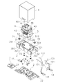
12 出力端子
15 回路
8 ダイオード
51 コイル
4 接点機構部
9 ヒューズ
1 逆流防止装置
3 端子台
10 接続部材
94 第1口金部
95 第2口金部
96 ガラス管部
91 ヒューズ本体
92 第1リード線
93 第2リード線
304 第1横支持リブ
305 第2横支持リブ
306 第3横支持リブ
307 第1上支持リブ
308 第2上支持リブ
Claims (10)
- 入力端子と、
出力端子と、
前記入力端子と前記出力端子とを接続する回路と、
前記回路において前記入力端子と前記出力端子との間に配置され、前記入力端子から前記出力端子への電流の流れを許容し、前記出力端子から前記入力端子への電流の流れを規制するダイオードと、
前記回路において前記入力端子と前記ダイオードとに直列に配置されるコイルと、
前記回路において前記ダイオードに並列に接続され、前記コイルに流れる電流が所定の動作閾値未満であるときには遮断状態を維持し、前記コイルに前記動作閾値以上の電流が流れることで接続状態となる接点機構部と、
前記回路において前記ダイオードに直列に接続されるヒューズと、
前記コイルと前記接点機構部とを支持し、前記入力端子と前記出力端子とが取り付けられる端子台と、
前記ヒューズと前記コイルとを接続する接続部材と、
を備え、
前記ヒューズは、前記端子台の内部に収容され、
前記ヒューズは、一対の口金部と、前記一対の口金部の間に配置されるガラス管部と、を有し、
前記接続部材は、前記一対の口金部の一方と交差するように配置される、
逆流防止装置。 - 前記入力端子は、前記端子台の一方の端部に配置され、
前記出力端子は、前記端子台の他方の端部に配置され、
前記ヒューズは、前記入力端子と前記出力端子との間に配置される、
請求項1に記載の逆流防止装置。 - 前記ヒューズは、前記端子台の長手方向に沿って配置される、
請求項1又は2に記載の逆流防止装置。 - 前記ヒューズと前記ダイオードとは、前記端子台の内部に収容されており、
前記入力端子は、前記端子台の第1の角部に配置され、
前記出力端子は、前記端子台の前記第1の角部の対角に位置する第2の角部に配置され、
前記ヒューズは、前記端子台の長手方向に沿って配置され、
前記ヒューズは、前記端子台の長手方向において前記入力端子と前記出力端子との間、且つ、前記端子台の短手方向において前記入力端子と前記出力端子との間に配置され、
前記ダイオードは、前記端子台の長手方向において前記ヒューズと前記出力端子との間、且つ、前記端子台の短手方向において前記ヒューズと前記出力端子との間に配置される、
請求項1に記載の逆流防止装置。 - 前記接続部材は、前記一対の口金部のうち前記接続部材と同極の前記口金部と交差するように配置される、
請求項1から4のいずれかに記載の逆流防止装置。 - 前記接続部材は、板状の形状を有する、
請求項1から5のいずれかに記載の逆流防止装置。 - 前記ヒューズは、ヒューズ本体と、前記ヒューズ本体から突出するリード線とを有し、
前記リード線は、前記接続部材に半田付けされており、
前記接続部材は、前記リード線が嵌合されるスリットを有する、
請求項1から6のいずれかに記載の逆流防止装置。 - 前記ヒューズは、基板を介さずに、前記リード線を介して前記入力端子又は前記出力端子に接続される、
請求項7に記載の逆流防止装置。 - 前記端子台は、前記接続部材に対向するように配置されるリブを有する、
請求項1から8のいずれかに記載の逆流防止装置。 - 前記端子台は、前記ヒューズに対向するように配置されるリブを有する、
請求項1から9のいずれかに記載の逆流防止装置。
Priority Applications (4)
| Application Number | Priority Date | Filing Date | Title |
|---|---|---|---|
| JP2013248253A JP6287128B2 (ja) | 2013-11-29 | 2013-11-29 | 逆流防止装置 |
| KR1020140162563A KR20150062958A (ko) | 2013-11-29 | 2014-11-20 | 역류 방지 장치 |
| CN201410691527.3A CN104682373B (zh) | 2013-11-29 | 2014-11-25 | 防逆流装置 |
| KR1020160156412A KR20160137904A (ko) | 2013-11-29 | 2016-11-23 | 역류 방지 장치 |
Applications Claiming Priority (1)
| Application Number | Priority Date | Filing Date | Title |
|---|---|---|---|
| JP2013248253A JP6287128B2 (ja) | 2013-11-29 | 2013-11-29 | 逆流防止装置 |
Publications (2)
| Publication Number | Publication Date |
|---|---|
| JP2015106989A JP2015106989A (ja) | 2015-06-08 |
| JP6287128B2 true JP6287128B2 (ja) | 2018-03-07 |
Family
ID=53317111
Family Applications (1)
| Application Number | Title | Priority Date | Filing Date |
|---|---|---|---|
| JP2013248253A Expired - Fee Related JP6287128B2 (ja) | 2013-11-29 | 2013-11-29 | 逆流防止装置 |
Country Status (3)
| Country | Link |
|---|---|
| JP (1) | JP6287128B2 (ja) |
| KR (2) | KR20150062958A (ja) |
| CN (1) | CN104682373B (ja) |
Families Citing this family (1)
| Publication number | Priority date | Publication date | Assignee | Title |
|---|---|---|---|---|
| CN113328698B (zh) * | 2021-08-02 | 2021-10-22 | 江苏泽润新材料有限公司 | 轴向二极管接线盒及其制造方法 |
Family Cites Families (11)
| Publication number | Priority date | Publication date | Assignee | Title |
|---|---|---|---|---|
| JPS5321403Y2 (ja) * | 1973-06-01 | 1978-06-05 | ||
| JPS54181272U (ja) * | 1978-06-13 | 1979-12-21 | ||
| JPH02126380U (ja) * | 1989-03-27 | 1990-10-18 | ||
| JP3289394B2 (ja) * | 1992-06-19 | 2002-06-04 | オムロン株式会社 | 逆流防止装置及び太陽電池保護装置 |
| JP3325299B2 (ja) * | 1992-09-10 | 2002-09-17 | 株式会社ソキア | 電源装置 |
| JPH10106658A (ja) * | 1996-09-30 | 1998-04-24 | Morimatsu:Kk | 着脱容易なヒューズ内蔵端子台 |
| JP2007325413A (ja) * | 2006-06-01 | 2007-12-13 | Nippon Telegr & Teleph Corp <Ntt> | 電流分配装置 |
| US8723031B2 (en) * | 2010-08-30 | 2014-05-13 | Hosiden Corporation | Terminal box |
| JP6024194B2 (ja) * | 2012-05-15 | 2016-11-09 | オムロン株式会社 | リレーユニットおよびその製造方法 |
| JP5831408B2 (ja) * | 2012-09-11 | 2015-12-09 | 株式会社オートネットワーク技術研究所 | 電気接続箱 |
| CN202898223U (zh) * | 2012-10-12 | 2013-04-24 | 好利来(中国)电子科技股份有限公司 | 一种玻璃管端部外圆周面磨砂处理的熔断器 |
-
2013
- 2013-11-29 JP JP2013248253A patent/JP6287128B2/ja not_active Expired - Fee Related
-
2014
- 2014-11-20 KR KR1020140162563A patent/KR20150062958A/ko not_active Ceased
- 2014-11-25 CN CN201410691527.3A patent/CN104682373B/zh active Active
-
2016
- 2016-11-23 KR KR1020160156412A patent/KR20160137904A/ko not_active Ceased
Also Published As
| Publication number | Publication date |
|---|---|
| KR20160137904A (ko) | 2016-12-01 |
| JP2015106989A (ja) | 2015-06-08 |
| CN104682373B (zh) | 2017-11-17 |
| CN104682373A (zh) | 2015-06-03 |
| KR20150062958A (ko) | 2015-06-08 |
Similar Documents
| Publication | Publication Date | Title |
|---|---|---|
| US8841979B2 (en) | Relay | |
| US8305166B2 (en) | Electromagnetic relay | |
| US10163588B2 (en) | Electromagnetic relay including yoke-retaining bottom plate | |
| US20130033344A1 (en) | Electromagnetic relay | |
| JP7026327B2 (ja) | 接点装置、電磁継電器及び電気機器 | |
| US9196433B2 (en) | Electromagnetic switch | |
| JP4950871B2 (ja) | 電磁スイッチ装置 | |
| JP2014165477A (ja) | 電子部品及び電子制御装置 | |
| JP6287128B2 (ja) | 逆流防止装置 | |
| JP2016071937A (ja) | バッテリ端子 | |
| CN204289343U (zh) | 熔断器 | |
| JP7076635B2 (ja) | 回路遮断器 | |
| KR101503316B1 (ko) | 전자접촉기 | |
| KR20160008823A (ko) | 복수의 2차 배터리 셀들의 병렬 연결에 의해 형성되는 배터리 팩 | |
| JP6175256B2 (ja) | ヒューズ | |
| CN203387436U (zh) | 防逆流装置以及具备其的太阳光发电系统 | |
| KR20160030170A (ko) | 퓨즈 | |
| CN204289344U (zh) | 熔断器 | |
| JP6739922B2 (ja) | ヒューズ素子 | |
| JP2010062078A (ja) | 電磁接触器 | |
| JP5922426B2 (ja) | 回路遮断器 | |
| JP2017098194A (ja) | 直流開閉器 | |
| JP5189919B2 (ja) | ヒューズ | |
| JP2014053201A5 (ja) | ||
| JP2011243513A (ja) | 直流電流遮断用小形スイッチ |
Legal Events
| Date | Code | Title | Description |
|---|---|---|---|
| A621 | Written request for application examination |
Free format text: JAPANESE INTERMEDIATE CODE: A621 Effective date: 20161005 |
|
| A977 | Report on retrieval |
Free format text: JAPANESE INTERMEDIATE CODE: A971007 Effective date: 20170623 |
|
| A131 | Notification of reasons for refusal |
Free format text: JAPANESE INTERMEDIATE CODE: A131 Effective date: 20170704 |
|
| A521 | Request for written amendment filed |
Free format text: JAPANESE INTERMEDIATE CODE: A523 Effective date: 20170901 |
|
| RD03 | Notification of appointment of power of attorney |
Free format text: JAPANESE INTERMEDIATE CODE: A7423 Effective date: 20170901 |
|
| RD04 | Notification of resignation of power of attorney |
Free format text: JAPANESE INTERMEDIATE CODE: A7424 Effective date: 20170901 |
|
| A131 | Notification of reasons for refusal |
Free format text: JAPANESE INTERMEDIATE CODE: A131 Effective date: 20171031 |
|
| A521 | Request for written amendment filed |
Free format text: JAPANESE INTERMEDIATE CODE: A523 Effective date: 20171218 |
|
| TRDD | Decision of grant or rejection written | ||
| A01 | Written decision to grant a patent or to grant a registration (utility model) |
Free format text: JAPANESE INTERMEDIATE CODE: A01 Effective date: 20180109 |
|
| A61 | First payment of annual fees (during grant procedure) |
Free format text: JAPANESE INTERMEDIATE CODE: A61 Effective date: 20180122 |
|
| R150 | Certificate of patent or registration of utility model |
Ref document number: 6287128 Country of ref document: JP Free format text: JAPANESE INTERMEDIATE CODE: R150 |
|
| LAPS | Cancellation because of no payment of annual fees |