JP6288048B2 - Shift control device for automatic transmission - Google Patents
Shift control device for automatic transmission Download PDFInfo
- Publication number
- JP6288048B2 JP6288048B2 JP2015226288A JP2015226288A JP6288048B2 JP 6288048 B2 JP6288048 B2 JP 6288048B2 JP 2015226288 A JP2015226288 A JP 2015226288A JP 2015226288 A JP2015226288 A JP 2015226288A JP 6288048 B2 JP6288048 B2 JP 6288048B2
- Authority
- JP
- Japan
- Prior art keywords
- torque
- engagement mechanism
- friction engagement
- engine
- speed
- Prior art date
- Legal status (The legal status is an assumption and is not a legal conclusion. Google has not performed a legal analysis and makes no representation as to the accuracy of the status listed.)
- Active
Links
Images
Classifications
-
- F—MECHANICAL ENGINEERING; LIGHTING; HEATING; WEAPONS; BLASTING
- F16—ENGINEERING ELEMENTS AND UNITS; GENERAL MEASURES FOR PRODUCING AND MAINTAINING EFFECTIVE FUNCTIONING OF MACHINES OR INSTALLATIONS; THERMAL INSULATION IN GENERAL
- F16H—GEARING
- F16H61/00—Control functions within control units of change-speed- or reversing-gearings for conveying rotary motion ; Control of exclusively fluid gearing, friction gearing, gearings with endless flexible members or other particular types of gearing
- F16H61/04—Smoothing ratio shift
-
- B—PERFORMING OPERATIONS; TRANSPORTING
- B60—VEHICLES IN GENERAL
- B60W—CONJOINT CONTROL OF VEHICLE SUB-UNITS OF DIFFERENT TYPE OR DIFFERENT FUNCTION; CONTROL SYSTEMS SPECIALLY ADAPTED FOR HYBRID VEHICLES; ROAD VEHICLE DRIVE CONTROL SYSTEMS FOR PURPOSES NOT RELATED TO THE CONTROL OF A PARTICULAR SUB-UNIT
- B60W30/00—Purposes of road vehicle drive control systems not related to the control of a particular sub-unit, e.g. of systems using conjoint control of vehicle sub-units
- B60W30/18—Propelling the vehicle
- B60W30/188—Controlling power parameters of the driveline, e.g. determining the required power
-
- B—PERFORMING OPERATIONS; TRANSPORTING
- B60—VEHICLES IN GENERAL
- B60W—CONJOINT CONTROL OF VEHICLE SUB-UNITS OF DIFFERENT TYPE OR DIFFERENT FUNCTION; CONTROL SYSTEMS SPECIALLY ADAPTED FOR HYBRID VEHICLES; ROAD VEHICLE DRIVE CONTROL SYSTEMS FOR PURPOSES NOT RELATED TO THE CONTROL OF A PARTICULAR SUB-UNIT
- B60W10/00—Conjoint control of vehicle sub-units of different type or different function
- B60W10/02—Conjoint control of vehicle sub-units of different type or different function including control of driveline clutches
-
- B—PERFORMING OPERATIONS; TRANSPORTING
- B60—VEHICLES IN GENERAL
- B60W—CONJOINT CONTROL OF VEHICLE SUB-UNITS OF DIFFERENT TYPE OR DIFFERENT FUNCTION; CONTROL SYSTEMS SPECIALLY ADAPTED FOR HYBRID VEHICLES; ROAD VEHICLE DRIVE CONTROL SYSTEMS FOR PURPOSES NOT RELATED TO THE CONTROL OF A PARTICULAR SUB-UNIT
- B60W10/00—Conjoint control of vehicle sub-units of different type or different function
- B60W10/04—Conjoint control of vehicle sub-units of different type or different function including control of propulsion units
- B60W10/06—Conjoint control of vehicle sub-units of different type or different function including control of propulsion units including control of combustion engines
-
- F—MECHANICAL ENGINEERING; LIGHTING; HEATING; WEAPONS; BLASTING
- F16—ENGINEERING ELEMENTS AND UNITS; GENERAL MEASURES FOR PRODUCING AND MAINTAINING EFFECTIVE FUNCTIONING OF MACHINES OR INSTALLATIONS; THERMAL INSULATION IN GENERAL
- F16H—GEARING
- F16H61/00—Control functions within control units of change-speed- or reversing-gearings for conveying rotary motion ; Control of exclusively fluid gearing, friction gearing, gearings with endless flexible members or other particular types of gearing
- F16H61/04—Smoothing ratio shift
- F16H61/0437—Smoothing ratio shift by using electrical signals
-
- F—MECHANICAL ENGINEERING; LIGHTING; HEATING; WEAPONS; BLASTING
- F16—ENGINEERING ELEMENTS AND UNITS; GENERAL MEASURES FOR PRODUCING AND MAINTAINING EFFECTIVE FUNCTIONING OF MACHINES OR INSTALLATIONS; THERMAL INSULATION IN GENERAL
- F16H—GEARING
- F16H61/00—Control functions within control units of change-speed- or reversing-gearings for conveying rotary motion ; Control of exclusively fluid gearing, friction gearing, gearings with endless flexible members or other particular types of gearing
- F16H61/04—Smoothing ratio shift
- F16H61/06—Smoothing ratio shift by controlling rate of change of fluid pressure
- F16H61/061—Smoothing ratio shift by controlling rate of change of fluid pressure using electric control means
-
- F—MECHANICAL ENGINEERING; LIGHTING; HEATING; WEAPONS; BLASTING
- F16—ENGINEERING ELEMENTS AND UNITS; GENERAL MEASURES FOR PRODUCING AND MAINTAINING EFFECTIVE FUNCTIONING OF MACHINES OR INSTALLATIONS; THERMAL INSULATION IN GENERAL
- F16H—GEARING
- F16H63/00—Control outputs from the control unit to change-speed- or reversing-gearings for conveying rotary motion or to other devices than the final output mechanism
- F16H63/40—Control outputs from the control unit to change-speed- or reversing-gearings for conveying rotary motion or to other devices than the final output mechanism comprising signals other than signals for actuating the final output mechanisms
- F16H63/50—Signals to an engine or motor
- F16H63/502—Signals to an engine or motor for smoothing gear shifts
-
- B—PERFORMING OPERATIONS; TRANSPORTING
- B60—VEHICLES IN GENERAL
- B60W—CONJOINT CONTROL OF VEHICLE SUB-UNITS OF DIFFERENT TYPE OR DIFFERENT FUNCTION; CONTROL SYSTEMS SPECIALLY ADAPTED FOR HYBRID VEHICLES; ROAD VEHICLE DRIVE CONTROL SYSTEMS FOR PURPOSES NOT RELATED TO THE CONTROL OF A PARTICULAR SUB-UNIT
- B60W2510/00—Input parameters relating to a particular sub-units
- B60W2510/02—Clutches
- B60W2510/0275—Clutch torque
-
- B—PERFORMING OPERATIONS; TRANSPORTING
- B60—VEHICLES IN GENERAL
- B60W—CONJOINT CONTROL OF VEHICLE SUB-UNITS OF DIFFERENT TYPE OR DIFFERENT FUNCTION; CONTROL SYSTEMS SPECIALLY ADAPTED FOR HYBRID VEHICLES; ROAD VEHICLE DRIVE CONTROL SYSTEMS FOR PURPOSES NOT RELATED TO THE CONTROL OF A PARTICULAR SUB-UNIT
- B60W2510/00—Input parameters relating to a particular sub-units
- B60W2510/06—Combustion engines, Gas turbines
- B60W2510/0638—Engine speed
-
- B—PERFORMING OPERATIONS; TRANSPORTING
- B60—VEHICLES IN GENERAL
- B60W—CONJOINT CONTROL OF VEHICLE SUB-UNITS OF DIFFERENT TYPE OR DIFFERENT FUNCTION; CONTROL SYSTEMS SPECIALLY ADAPTED FOR HYBRID VEHICLES; ROAD VEHICLE DRIVE CONTROL SYSTEMS FOR PURPOSES NOT RELATED TO THE CONTROL OF A PARTICULAR SUB-UNIT
- B60W2510/00—Input parameters relating to a particular sub-units
- B60W2510/06—Combustion engines, Gas turbines
- B60W2510/0657—Engine torque
-
- B—PERFORMING OPERATIONS; TRANSPORTING
- B60—VEHICLES IN GENERAL
- B60W—CONJOINT CONTROL OF VEHICLE SUB-UNITS OF DIFFERENT TYPE OR DIFFERENT FUNCTION; CONTROL SYSTEMS SPECIALLY ADAPTED FOR HYBRID VEHICLES; ROAD VEHICLE DRIVE CONTROL SYSTEMS FOR PURPOSES NOT RELATED TO THE CONTROL OF A PARTICULAR SUB-UNIT
- B60W2510/00—Input parameters relating to a particular sub-units
- B60W2510/10—Change speed gearings
- B60W2510/1015—Input shaft speed, e.g. turbine speed
- B60W2510/102—Input speed change rate
-
- B—PERFORMING OPERATIONS; TRANSPORTING
- B60—VEHICLES IN GENERAL
- B60W—CONJOINT CONTROL OF VEHICLE SUB-UNITS OF DIFFERENT TYPE OR DIFFERENT FUNCTION; CONTROL SYSTEMS SPECIALLY ADAPTED FOR HYBRID VEHICLES; ROAD VEHICLE DRIVE CONTROL SYSTEMS FOR PURPOSES NOT RELATED TO THE CONTROL OF A PARTICULAR SUB-UNIT
- B60W2710/00—Output or target parameters relating to a particular sub-units
- B60W2710/02—Clutches
- B60W2710/027—Clutch torque
-
- B—PERFORMING OPERATIONS; TRANSPORTING
- B60—VEHICLES IN GENERAL
- B60W—CONJOINT CONTROL OF VEHICLE SUB-UNITS OF DIFFERENT TYPE OR DIFFERENT FUNCTION; CONTROL SYSTEMS SPECIALLY ADAPTED FOR HYBRID VEHICLES; ROAD VEHICLE DRIVE CONTROL SYSTEMS FOR PURPOSES NOT RELATED TO THE CONTROL OF A PARTICULAR SUB-UNIT
- B60W2710/00—Output or target parameters relating to a particular sub-units
- B60W2710/06—Combustion engines, Gas turbines
- B60W2710/0644—Engine speed
-
- B—PERFORMING OPERATIONS; TRANSPORTING
- B60—VEHICLES IN GENERAL
- B60W—CONJOINT CONTROL OF VEHICLE SUB-UNITS OF DIFFERENT TYPE OR DIFFERENT FUNCTION; CONTROL SYSTEMS SPECIALLY ADAPTED FOR HYBRID VEHICLES; ROAD VEHICLE DRIVE CONTROL SYSTEMS FOR PURPOSES NOT RELATED TO THE CONTROL OF A PARTICULAR SUB-UNIT
- B60W2710/00—Output or target parameters relating to a particular sub-units
- B60W2710/06—Combustion engines, Gas turbines
- B60W2710/0666—Engine torque
-
- B—PERFORMING OPERATIONS; TRANSPORTING
- B60—VEHICLES IN GENERAL
- B60W—CONJOINT CONTROL OF VEHICLE SUB-UNITS OF DIFFERENT TYPE OR DIFFERENT FUNCTION; CONTROL SYSTEMS SPECIALLY ADAPTED FOR HYBRID VEHICLES; ROAD VEHICLE DRIVE CONTROL SYSTEMS FOR PURPOSES NOT RELATED TO THE CONTROL OF A PARTICULAR SUB-UNIT
- B60W2710/00—Output or target parameters relating to a particular sub-units
- B60W2710/10—Change speed gearings
- B60W2710/105—Output torque
Landscapes
- Engineering & Computer Science (AREA)
- General Engineering & Computer Science (AREA)
- Mechanical Engineering (AREA)
- Chemical & Material Sciences (AREA)
- Combustion & Propulsion (AREA)
- Transportation (AREA)
- Physics & Mathematics (AREA)
- Fluid Mechanics (AREA)
- Automation & Control Theory (AREA)
- Control Of Transmission Device (AREA)
- Control Of Driving Devices And Active Controlling Of Vehicle (AREA)
- Control Of Vehicle Engines Or Engines For Specific Uses (AREA)
Description
本発明は、変速比をステップ的に変化させる自動変速機における変速を制御する装置に関するものである。 The present invention relates to an apparatus for controlling a shift in an automatic transmission that changes a gear ratio stepwise.
加速操作されて車速が増大し、それに伴って変速比を低下させるアップシフトは、エンジンなどの駆動力源の出力が増大している状態で駆動力源の回転数を低下させる変速になるので、変速に伴って駆動力が変化しやすい。特に低速側の変速段で係合していた係合機構を解放し、かつ変速後の高速側の変速段を設定する係合機構を係合させるクラッチ・ツウ・クラッチ変速では、切替過程における各係合機構のトルク容量の過不足などが原因で駆動力が落ち込んだり、あるいは駆動力の変化幅が大きくなってショックが生じたりしやすい。特許文献1には、クラッチ・ツウ・クラッチ変速におけるトルク相での駆動力の落ち込みやショックを低減するために、駆動力源であるモータあるいはエンジンでトルク補償を行うように構成された装置が記載されている。特許文献1に記載された装置では、トルク補償量を実験などによって決めておき、トルク補償のタイミングを学習している。また、その学習の進行の程度に応じてトルク補償率を変更しており、学習が進行していない状態ではトルク補償率を小さくしている。 The upshift that increases the vehicle speed when the acceleration operation is performed and decreases the gear ratio accordingly is a shift that decreases the rotation speed of the driving force source while the output of the driving force source such as the engine is increasing. The driving force is likely to change with the shift. In particular, in clutch-to-clutch shifts in which the engagement mechanism engaged at the low-speed side gear stage is released and the engagement mechanism for setting the high-speed side gear stage after the shift is engaged, The driving force is likely to drop due to excessive or insufficient torque capacity of the engagement mechanism, or the variation range of the driving force is likely to cause a shock. Patent Document 1 describes an apparatus configured to perform torque compensation with a motor or engine that is a driving force source in order to reduce a drop in driving force or a shock in a torque phase in clutch-to-clutch shifting. Has been. In the apparatus described in Patent Document 1, the amount of torque compensation is determined by experiment or the like, and the timing of torque compensation is learned. Further, the torque compensation rate is changed according to the progress of the learning, and the torque compensation rate is reduced when the learning is not progressing.
また、自動変速機における変速に関与するクラッチの制御として、目標回転数と実回転数との変速に基づいて、クラッチのトルク容量をフィードバック制御する装置が特許文献2に記載されている。さらに、特許文献3には、パワーオンダウンシフトの際にエンジントルクを補正するように構成された装置が記載されている。この特許文献3に記載された装置は、パワーオンダウンシフト時の入力回転数についての目標値と実際値との偏差に基づいてエネルギの過不足分を算出し、算出されたエネルギの過不足分に応じてエンジントルクを補正するように構成されている。 Japanese Patent Application Laid-Open No. 2004-228688 discloses a device that feedback-controls the torque capacity of a clutch based on a shift between a target rotational speed and an actual rotational speed as control of a clutch involved in the shift in an automatic transmission. Further, Patent Document 3 describes an apparatus configured to correct engine torque during a power-on downshift. The device described in Patent Document 3 calculates an excess or deficiency of energy based on a deviation between a target value and an actual value for the input rotation speed at the time of power-on downshift, and the calculated excess or deficiency of energy. The engine torque is corrected according to
特許文献1に記載された装置は、変速時のトルク補償量を実験で求めたトルクとしている。しかしながら、駆動力源としてエンジン(内燃機関)を使用している場合、エンジンの出力トルクには不可避的なばらつきがあり、また変速を実行するクラッチなどの摩擦係合機構の伝達トルク容量に不可避的なばらつきがある。そのため、トルク補償量を実験などで求めた一定値にすると、エンジントルクのばらつきや摩擦係合機構の伝達トルク容量のばらつきを反映した制御を行うことができないので、駆動力の落ち込みやショックを必ずしも十分には抑制することができない可能性がある。また、特許文献1に記載された装置は、前記学習が進行していない状態ではトルク補償率を小さくして、トルク補償による影響を低減している。しかしながら、学習制御は過去のデータに基づく制御であって現在時点の状態をリアルタイムで反映させる制御ではないうえに、学習が進行していない状態とトルク補償率を小さくすることとの相関関係が必ずしも正確には一致もしくは対応している訳ではないので、駆動力の落ち込みやショックなどを十分に抑制するには改善の余地がある。 In the device described in Patent Document 1, the torque compensation amount at the time of shifting is set as a torque obtained through experiments. However, when an engine (internal combustion engine) is used as a driving force source, there is an unavoidable variation in the output torque of the engine, and the transmission torque capacity of a friction engagement mechanism such as a clutch that performs a shift is unavoidable. There is a lot of variation. For this reason, if the torque compensation amount is set to a constant value obtained through experiments or the like, control that reflects variations in engine torque and transmission torque capacity of the friction engagement mechanism cannot be performed. There is a possibility that it cannot be sufficiently suppressed. The device described in Patent Document 1 reduces the influence of torque compensation by reducing the torque compensation rate when the learning is not progressing. However, the learning control is based on past data and does not reflect the current state in real time, and the correlation between the state where learning is not progressing and the torque compensation rate is reduced is not always necessary. Since they do not exactly match or correspond to each other, there is room for improvement in order to sufficiently suppress a drop in driving force or a shock.
なお、クラッチ・ツウ・クラッチ変速の際の駆動力の落ち込みやショックを抑制するためには、特許文献1に記載されているようにエンジントルクによる補償を行うことが好ましい。しかしながら、特許文献2に記載された装置は、エンジン回転数を目標回転数に追従させるべくクラッチの伝達トルク容量をフィードバック制御する装置であるから、特許文献2に記載された装置は、クラッチ・ツウ・クラッチ変速の際の駆動力の落ち込みやショックの改善には使用することができない。また、特許文献3に記載された装置は、パワーオンダウンシフトの際のエンジントルクを制御する装置であるから、アップシフトの制御に直ちには使用することができない。しかも、特許文献3に記載された装置は、変速の際のエネルギの過不足をエンジントルクで是正するように構成されているので、入力回転数を目標値に追従させることができるとしても、アップシフトの際のトルク相での駆動力の落ち込みやショックを抑制することは困難である。
In order to suppress a drop in driving force and a shock at the time of clutch-to-clutch shifting, it is preferable to perform compensation by engine torque as described in Patent Document 1. However, the device described in
本発明は上記の技術的課題に着目してなされたものであって、クラッチ・ツウ・クラッチ変速でのアップシフトの際における駆動力の落ち込みやショックなどを効果的に抑制することのできる変速制御装置を提供することを目的とするものである。 The present invention has been made paying attention to the above technical problem, and is capable of effectively suppressing a drop in driving force or a shock during an upshift in clutch-to-clutch shift. The object is to provide an apparatus.
本発明は、上記の目的を達成するために、低速側の変速段で係合させられる第1摩擦係合機構と、前記低速側の変速段より変速比が小さい高速側の変速段で係合させられる第2摩擦係合機構とを有する自動変速機がエンジンの出力側に連結され、前記エンジンがトルクを出力している状態で、第1摩擦係合機構を解放させかつ前記第2摩擦係合機構を係合させることによりアップシフトを行う自動変速機の変速制御装置であって、前記アップシフトの際に前記第1摩擦係合機構と前記第2摩擦係合機構と前記エンジンとを制御するコントローラを有し、前記コントローラは、前記アップシフトの際に前記第1摩擦係合機構の伝達トルク容量を予め定めた勾配で低下させるとともに、前記第1摩擦係合機構の伝達トルク容量の低下に従って前記第2摩擦係合機構の伝達トルク容量を増大させ、前記第1摩擦係合機構の伝達トルク容量を低下させるとともに前記第2摩擦係合機構の伝達トルク容量を増大させているトルク相において、前記低速側の変速段での前記エンジンの同期回転数より予め定めた所定回転数高い回転数を前記エンジンの目標回転数として設定し、前記トルク相において前記エンジンの回転数を前記目標回転数に一致させるように前記エンジンのトルクを、前記エンジンの回転数と前記目標回転数との偏差に基づいてフィードバック制御するように構成されていることを特徴とするものである。 In order to achieve the above object, the present invention engages a first friction engagement mechanism that is engaged at a low-speed gear stage and a high-speed gear stage that has a lower gear ratio than the low-speed gear stage. An automatic transmission having a second frictional engagement mechanism that is connected to an output side of the engine, and in a state where the engine is outputting torque, the first frictional engagement mechanism is released and the second frictional engagement mechanism is released. A shift control apparatus for an automatic transmission that performs an upshift by engaging a combination mechanism, and controls the first friction engagement mechanism, the second friction engagement mechanism, and the engine during the upshift. The controller reduces the transmission torque capacity of the first friction engagement mechanism at a predetermined gradient and reduces the transmission torque capacity of the first friction engagement mechanism during the upshift. According to the above 2 in the torque phase in which the transmission torque capacity of the second friction engagement mechanism is increased while the transmission torque capacity of the second friction engagement mechanism is increased while the transmission torque capacity of the second friction engagement mechanism is increased. A predetermined number of revolutions higher than the synchronous number of revolutions of the engine at the gear position on the side is set as the target revolution number of the engine, and the revolution number of the engine coincides with the target revolution number in the torque phase Thus, the engine torque is configured to be feedback-controlled based on a deviation between the engine speed and the target speed.
本発明においては、前記コントローラは、前記自動変速機の出力軸トルクと前記自動変速機の入力トルクと前記第1摩擦係合機構のトルクと前記第2摩擦係合機構のトルクとの関係を定めている運動方程式と、前記自動変速機の入力回転数の変化率と前記自動変速機の入力トルクと前記第1摩擦係合機構のトルクと前記第2摩擦係合機構のトルクとの関係を定めている運動方程式とを使用し、かつ前記出力軸トルクを一定値とするとともに前記入力回転数の変化率を前記アップシフト開始前の値にして前記エンジンのトルクと前記第2摩擦係合機構のトルクとを算出し、前記フィードバック制御は、前記運動方程式から算出されたトルクを補正する制御であってよい。 In the present invention, the controller determines a relationship among an output shaft torque of the automatic transmission, an input torque of the automatic transmission, a torque of the first friction engagement mechanism, and a torque of the second friction engagement mechanism. A relationship between the equation of motion, the rate of change in the input rotational speed of the automatic transmission, the input torque of the automatic transmission, the torque of the first friction engagement mechanism, and the torque of the second friction engagement mechanism. And the output shaft torque is set to a constant value, and the rate of change of the input rotational speed is set to a value before the start of the upshift, and the torque of the engine and the second friction engagement mechanism Torque is calculated, and the feedback control may be control for correcting the torque calculated from the equation of motion.
本発明においては、前記コントローラは、前記第1摩擦係合機構の伝達トルク容量が予め定めた所定値以下に低下して前記第1摩擦係合機構が解放状態になった場合に、前記エンジンのトルクを前記第1摩擦係合機構が解放状態になった際のトルクに保持し、かつ前記第2摩擦係合機構の伝達トルク容量を前記第1摩擦係合機構が解放状態になった際の伝達トルク容量の増大率で増大させるように構成されていてよい。 In the present invention, when the transmission torque capacity of the first friction engagement mechanism is reduced to a predetermined value or less and the first friction engagement mechanism is released, the controller controls the engine. The torque is maintained at the torque when the first friction engagement mechanism is released, and the transmission torque capacity of the second friction engagement mechanism is maintained when the first friction engagement mechanism is released. The transmission torque capacity may be increased at an increasing rate.
本発明によれば、クラッチ・ツウ・クラッチ変速のアップシフトにおけるトルク相では、エンジンの回転数が変速前の低速段での同期回転数より高い回転数となるように、エンジントルクがフィードバック制御される。エンジントルクや摩擦係合機構のトルクのバラツキは、エンジン回転数の増大もしくは低下となって現れる。本発明の変速制御装置では、トルク相において、エンジン回転数を変速前の低速段での同期回転数より高い回転数に維持するので、エンジントルクや摩擦係合機構のトルクのバラツキがあってもエンジン回転数が同期回転数を大きく下回ることを抑制することができる。そして、エンジン回転数のそのような制御は、エンジントルクをフィードバック制御することにより行われるので、エンジントルクはエンジン回転数を同期回転数に維持するトルクより大きくなる。そのため、エンジントルクや摩擦係合機構の伝達トルク容量にバラツキがあっても、アップシフトのトルク相において駆動トルクが大きく落ち込むことを防止もしくは抑制することができる。 According to the present invention, in the torque phase in the upshift of the clutch-to-clutch shift, the engine torque is feedback-controlled so that the engine speed is higher than the synchronous speed at the low speed stage before the speed change. The Variations in engine torque and torque in the friction engagement mechanism appear as an increase or decrease in engine speed. In the speed change control device of the present invention, in the torque phase, the engine speed is maintained at a higher speed than the synchronous speed at the low speed stage before the speed change, so even if there is a variation in engine torque or frictional engagement mechanism torque. It is possible to suppress the engine speed from significantly lowering the synchronous speed. Since such control of the engine speed is performed by feedback control of the engine torque, the engine torque becomes larger than the torque that maintains the engine speed at the synchronous speed. For this reason, even if the engine torque or the transmission torque capacity of the friction engagement mechanism varies, it is possible to prevent or suppress the drive torque from greatly dropping in the torque phase of the upshift.
また、本発明によれば、トルク相でのエンジントルクおよび第2摩擦係合機構のトルクを運動方程式に基づいて求めた値に制御し、かつエンジントルクについては、目標回転数との偏差を制御偏差とするフィードバック制御によって、前記運動方程式から求められたトルクを補正するから、トルク相での駆動トルクの落ち込みをより確実に防止もしくは抑制することができる。 Further, according to the present invention, the engine torque in the torque phase and the torque of the second friction engagement mechanism are controlled to values obtained based on the equation of motion, and the deviation of the engine torque from the target rotational speed is controlled. Since the torque obtained from the equation of motion is corrected by feedback control as a deviation, it is possible to more reliably prevent or suppress a drop in driving torque in the torque phase.
さらに、本発明によれば、第1摩擦係合機構が解放状態になった場合、エンジントルクを第1摩擦係合機構が解放状態になった時点のトルクに保持し、かつ係合側の第2摩擦係合機構の伝達トルク容量を第1摩擦係合機構が解放状態になった時点の増大率で増大させ続けるので、第2摩擦係合機構の伝達トルク容量にバラツキがあったとしても、エンジン回転数が過度に吹き上がったり、あるいは駆動トルクが大きく落ち込むなどの事態を防止もしくは抑制することができる。 Further, according to the present invention, when the first friction engagement mechanism is released, the engine torque is maintained at the torque at the time when the first friction engagement mechanism is released, and the engagement side Since the transmission torque capacity of the second friction engagement mechanism continues to increase at an increase rate at the time when the first friction engagement mechanism is released, even if there is a variation in the transmission torque capacity of the second friction engagement mechanism, It is possible to prevent or suppress a situation in which the engine speed is excessively increased or the driving torque is greatly reduced.
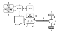
図1は本発明で対象とする自動変速機を有する車両のパワートレーンを模式的に示しており、駆動力源であるエンジン(内燃機関)1の出力側に自動変速機2が連結されている。自動変速機2は、変速比が互いに異なる複数の変速段を設定することのできる有段変速機であり、クラッチやブレーキなどの係合機構(以下、単にクラッチと記す)の係合および解放の組み合わせに応じた変速段(変速比)が設定されるように構成されている。そのクラッチは、一例として、油圧によって係合および解放させられ、また油圧に応じた伝達トルク容量を持つ油圧式の摩擦係合機構である。図1には、所定の低速側の変速段で係合させられるクラッチC1と、その低速側の変速段より高速側の他の変速段で係合させられるクラッチC2とを模式的に示してある。なお、クラッチC1が本発明の実施形態における第1摩擦係合機構に相当し、クラッチC2が本発明の実施形態における第2摩擦係合機構に相当する。自動変速機2の出力側にプロペラシャフト3が連結され、そのプロペラシャフト3は終減速機であるデファレンシャルギヤ4に連結されている。そのデファレンシャルギヤ4から左右の車軸5を介して駆動輪6に駆動力(駆動トルク)を伝達するように構成されている。
FIG. 1 schematically shows a power train of a vehicle having an automatic transmission which is a subject of the present invention, and an
エンジン1は、燃料の供給や点火時期あるいは燃焼気筒数を電気的に制御できるように構成されている。その制御を行うための電子制御装置(E−ECU)7が設けられている。このE−ECU7は、マイクロコンピュータを主体として構成され、入力されたデータや予め記憶しているデータを使用して演算を行い、その演算の結果を制御指令信号としてエンジン1に出力するように構成されている。このE−ECU7には、車速センサ8やアクセル開度センサ9、エンジン回転数センサ(図示せず)などが連結され、車両の走行状態を示すデータとして車速やアクセル開度、エンジン回転数などが各センサからE−ECU7に入力されている。
The engine 1 is configured to be able to electrically control fuel supply, ignition timing, or the number of combustion cylinders. An electronic control unit (E-ECU) 7 for performing the control is provided. The E-ECU 7 is configured mainly with a microcomputer, configured to perform calculation using input data or data stored in advance, and output the result of the calculation to the engine 1 as a control command signal. Has been. The E-ECU 7 is connected to a
自動変速機2は、上記のクラッチの係合および解放の状態に応じて所定の変速段に設定される歯車変速機構と、その歯車変速機構の入力側に配置されたトルクコンバータ(図示せず)とを備えている。なお、歯車変速機構は例えば前掲の特許文献1に記載されている構成と同様の構成の機構であってよい。また、トルクコンバータはロックアップクラッチを有する従来知られている構成のものであってよい。そのロックアップクラッチや前述したクラッチの係合や解放の制御を主として行う油圧制御部10が設けられている。油圧制御部10は、電気的に制御されるバルブ(図示せず)によってライン圧を制御し、またロックアップクラッチやクラッチなどに対する油圧の供給および排出、ならびにクラッチの伝達トルク容量を設定するための油圧などを制御するように構成されている。この油圧制御部10は、従来知られている車両用自動変速機に備えられている油圧制御部と同様の構成のものであってよい。
The
油圧制御部10を介して自動変速機2を制御するための電子制御装置(T−ECU)11が設けられている。このT−ECU11は、マイクロコンピュータを主体として構成されており、上記のE−ECU7とデータ通信可能に接続されている。また、T−ECU11は、車速やアクセル開度などのデータが入力され、それらの入力されたデータおよび予め記憶しているデータを使用して演算を行い、演算結果を制御指令信号として油圧制御部10に出力するように構成されている。T−ECU11が予め記憶しているデータには、変速線図が含まれる。変速線図は、一例として、車速とアクセル開度とによって変速段の領域を定めた線図であって、アップシフト線とダウンシフト線とが定められ、車速とアクセル開度とによって決まる走行状態がアップシフト線を横切るように変化することによりアップシフトの判断が成立し、また走行状態がダウンシフト線を横切るように変化することによりダウンシフトの判断が成立するように構成されている。
An electronic control unit (T-ECU) 11 for controlling the
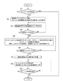
車速の増大によってアップシフトの判断が成立し、そのアップシフトがクラッチC1を解放し、かつクラッチC2を係合させる変速(クラッチ・ツウ・クラッチ変速)の場合、本発明の実施形態における変速制御装置は、以下に説明する制御を実行するように構成されている。図2にその制御の一例をフローチャートで記載してあり、ここに示す各ステップでの制御は、クラッチ・ツウ・クラッチ変速のアップシフトにおけるトルク相において、前述したE−ECU7あるいはT−ECU11によって実行される。したがってこれらE−ECU7およびT−ECU11が、本発明の実施形態におけるコントローラに相当している。図2に示す制御例では、先ず、アップシフトの条件が成立した否かが判断される(ステップS1)。このアップシフトは、ここで説明している制御例では、前述した一方のクラッチC1(以下、解放側クラッチと記すことがある。)を解放し、かつ他方のクラッチC2(以下、係合側クラッチと記すことがある。)を係合させる変速である。このステップS1の判断は、前述したように、走行状態からアップシフト線を高車速側に横切るように変化したか否か、もしくはそのような走行状態の変化によって出力される変速信号の有無などによって行うことができる。
In the case where the shift determination is established by the increase in the vehicle speed and the upshift is a shift (clutch-to-clutch shift) in which the clutch C1 is released and the clutch C2 is engaged, the shift control device according to the embodiment of the present invention. Is configured to execute the control described below. FIG. 2 is a flowchart showing an example of the control, and the control at each step shown here is executed by the above-described E-ECU 7 or T-
ステップS1で否定的に判断された場合には、特に制御を行うことなく図1に示すルーチンを一旦終了する。これに対してステップS1で肯定的に判断された場合には、解放側クラッチC1に掛かるトルクが算出され、かつドライバーが要求する駆動力を伝達できる最低トルク(最低伝達トルク容量)が算出される(ステップS2)。エンジン1が出力するトルクは吸入空気量や燃料噴射量などに応じたトルクとなり、またアップシフト前の変速段での変速比やその変速段を設定しているクラッチC1の歯車機構中の位置などによってクラッチC1のトルクの入力トルクに対する比率が決まるから、これらエンジントルクや歯車機構の構成などに基づいてクラッチC1に掛かるトルクが算出される。また、ドライバーの要求駆動力は、車速やアクセル開度ならびに予め用意されている駆動力マップに基づいて求められ、その要求駆動力に応じたクラッチC1のトルク、すなわち要求駆動力を滑りを生じることなく伝達できるクラッチC1の最低トルクが算出される。 If the determination in step S1 is negative, the routine shown in FIG. 1 is temporarily terminated without performing any particular control. On the other hand, when an affirmative determination is made in step S1, the torque applied to the disengagement side clutch C1 is calculated, and the minimum torque (minimum transmission torque capacity) that can transmit the driving force requested by the driver is calculated. (Step S2). The torque output by the engine 1 is a torque according to the intake air amount, the fuel injection amount, etc., the gear ratio at the gear stage before the upshift, the position in the gear mechanism of the clutch C1 that sets the gear stage, etc. Since the ratio of the torque of the clutch C1 to the input torque is determined by this, the torque applied to the clutch C1 is calculated based on the engine torque, the configuration of the gear mechanism, and the like. Further, the driver's required driving force is obtained based on the vehicle speed, the accelerator opening, and a driving force map prepared in advance, and the torque of the clutch C1, corresponding to the required driving force, that is, the required driving force is caused to slip. The minimum torque of the clutch C1 that can be transmitted without any error is calculated.
自動変速機2で変速を生じることなく車両が定常的に走行している場合にはクラッチC1にはライン圧もしくはこれに近い油圧が供給され、その伝達トルク容量は要求駆動力に応じた伝達トルク容量よりも大きくなっている。そこで、ステップS2で上記の最低トルクが算出されると、アップシフトを実行するために、先ず、解放側クラッチC1の油圧が、上記の最低トルクに相当する油圧(最低伝達トルク容量を設定する油圧)にまで低下させられる。そして、解放側クラッチC1の油圧が前記最低トルクに相当する油圧からスイープダウンされる(ステップS3)。この場合の油圧の低下勾配は、変速の遅れの原因とならず、また制御がオーバーシュートすることがないなどの条件を満たすように設計上、予め決めておくことができる。なお、係合側クラッチC2の油圧が次第に増大させられる。
When the vehicle is traveling steadily without causing a shift in the
ついで、エンジン1の回転数Neの吹き上がりが判定される(ステップS4)。回転数の吹き上がりとは、回転数が想定もしくは規定している回転数より高い回転数になることであり、ここで説明している例では、エンジン1の回転数Neが変速前の低速側変速段での同期回転数より高回転数になることできる。なお、同期回転数は低速側変速段での変速比と車速(もしくは前記プロペラシャフト3の回転数である出力軸回転数)とに基づいて求められる。したがって、ステップS4の判定は、エンジン1の回転数Neが同期回転数に対して予め定められた回転数(例えば数十rpm)上回ったことによって行うことができる。 Next, it is determined whether or not the engine speed Ne has increased (step S4). The increase in the number of rotations means that the number of rotations is higher than the assumed or specified number of rotations. In the example described here, the number of rotations Ne of the engine 1 is low before shifting. The rotational speed can be higher than the synchronous rotational speed at the shift stage. The synchronous rotational speed is obtained based on the speed ratio at the low speed side gear and the vehicle speed (or the output shaft rotational speed that is the rotational speed of the propeller shaft 3). Therefore, the determination in step S4 can be performed when the rotational speed Ne of the engine 1 exceeds a predetermined rotational speed (for example, several tens of rpm) with respect to the synchronous rotational speed.
上記のステップS3での油圧のスイープダウンは、解放側クラッチC1が前記要求駆動力を滑りを生じることなく伝達できる最低の伝達トルク容量となっている状態からの油圧の低下であるから、ステップS3の制御を開始した後に解放側クラッチC1に滑りが生じてエンジン1の回転数Neが吹き上がる。したがって、エンジン1の回転数Neが吹き上がらずにステップS4で否定的に判断されている間は、ステップS3の制御が継続される。そして、解放側クラッチC1の油圧が低下してエンジン1の回転数Neが吹き上がることによりステップS4で肯定的に判断される。その場合は、ステップS5に進んで、エンジントルクTeと係合側クラッチC2のトルクが、自動変速機2のギヤトレーンの構成に応じた運動方程式から算出される。また、同時にエンジン1の回転数Neを同期回転数より高い回転数に維持するようにエンジントルクTeがフィードバック(FB)制御される。その運動方程式の一例は、以下のとおりである。
To=A・Tt−B・TC1+C・TC2
dωt/dt=D・Tt+E・TC1−F・TC2
ここで、Toは出力軸トルク(自動変速機2から出力されるトルク)であり、Ttは自動変速機2におけるトルクコンバータのタービンのトルクであって入力トルクに相当し、トルクコンバータにおけるロックアップクラッチが係合している場合にはエンジントルクTeに一致し、ロックアップクラッチが解放している場合には、エンジントルクTeにトルクコンバータの速度比を掛けた値となる。TC1は解放側クラッチC1のトルク、TC2は係合側クラッチC2のトルク、ωtはタービンの回転速度、AからFのそれぞれは実験などに基づいて求められた定数である。
Since the hydraulic pressure sweepdown in step S3 is a decrease in hydraulic pressure from a state in which the disengagement-side clutch C1 has the minimum transmission torque capacity that can transmit the requested driving force without causing slippage, step S3 is performed. After starting the control, slip occurs in the release side clutch C1, and the rotational speed Ne of the engine 1 increases. Therefore, the control in step S3 is continued while the rotational speed Ne of the engine 1 is not blown up and is determined negative in step S4. Then, when the hydraulic pressure of the release side clutch C1 decreases and the rotational speed Ne of the engine 1 increases, a positive determination is made in step S4. In that case, the process proceeds to step S5, and the engine torque Te and the torque of the engagement side clutch C2 are calculated from the equation of motion corresponding to the configuration of the gear train of the
T o = A · T t −B · TC 1 + C · TC 2
dω t / dt = D · T t + E · T C1 −F · T C2
Here, T o is the output shaft torque (torque output from the automatic transmission 2), T t is equivalent to the input torque to a torque of the torque converter in the
エンジントルクTeおよび係合側クラッチC2のトルクTC2を演算するのにあたって、出力軸トルクTOの値は、一定値に設定される。すなわち変化量ΔTOが「0」(ΔTO=0)となる値に設定される。その一定値は、アップシフトの判断が成立した時点のトルク値であってよい。また、タービン回転数ωtの変化率(dωt/dt)は、変速開始の前後で同じになるように設定し、具体的にはアップシフトの判断が成立した時点の同期回転数の変化率(Δ変速前同期回転数)と同じに設定する。そして、解放側クラッチC1のトルクは、ステップS3でスイープダウンされている油圧に応じた値となる。したがって、上述した二つの式に基づいてエンジントルクTeおよび係合側クラッチC2のトルクTC2を算出することができる。 When to compute the torque T C2 of the engine torque Te and the engagement-side clutch C2, the value of the output shaft torque T O is set to a constant value. That is, the change amount ΔT O is set to a value that is “0” (ΔT O = 0). The fixed value may be a torque value at the time when the upshift determination is established. Further, the change rate (dω t / dt) of the turbine rotation speed ω t is set to be the same before and after the start of the shift, and specifically, the change rate of the synchronous rotation speed at the time when the upshift determination is established. Set to be the same as (synchronous rotation speed before Δ shift). The torque of the release side clutch C1 becomes a value corresponding to the hydraulic pressure that is swept down in step S3. Therefore, it is possible to calculate the torque T C2 of the engine torque Te and the engagement-side clutch C2 on the basis of the two equations described above.
また、維持されるエンジン回転数Neは、アップシフト前の変速段(低速段)での同期回転数に所定の偏差(スリップ回転数)を加算した回転数である。したがって、エンジン回転数Neを維持する制御は、上述した同期回転数に加算される回転数(いわゆるスリップ回転数)を一定に維持する制御になる。設計上定められたスリップ回転数と検出された実際の回転数との差を制御偏差として、エンジントルクTeがFB制御される。その制御は、前記運動方程式から求めたエンジントルクTeを補正する制御であってよい。エンジン1の出力トルクは、吸入空気量および燃料噴射量によって変化し、またガソリンエンジンであれば、点火時期によっても変化するから、エンジントルクTeのFB制御は、スロットル開度あるいは点火時期を変化させることにより行ってもよい。なお、本発明の実施形態における変速制御装置は、要は、エンジントルクTeを、上記の設計上定められたスリップ回転数と検出された実際の回転数との差を制御偏差としてFB制御するから、前述した運動方程式から求められたエンジントルクTeをFB制御によって補正することに替えて、アップシフト制御開始時のエンジントルクTeや適宜に設定したエンジントルク値を上記のFB制御によって補正することとしてもよい。 Further, the maintained engine rotational speed Ne is a rotational speed obtained by adding a predetermined deviation (slip rotational speed) to the synchronous rotational speed at the shift stage (low speed stage) before the upshift. Therefore, the control for maintaining the engine rotational speed Ne is a control for maintaining the rotational speed (so-called slip rotational speed) added to the synchronous rotational speed described above constant. The engine torque Te is FB-controlled using the difference between the slip rotational speed determined by design and the detected actual rotational speed as a control deviation. The control may be control for correcting the engine torque Te obtained from the equation of motion. The output torque of the engine 1 varies depending on the intake air amount and the fuel injection amount, and in the case of a gasoline engine, it also varies depending on the ignition timing. Therefore, the FB control of the engine torque Te changes the throttle opening or the ignition timing. It may be done by. Note that the speed change control apparatus according to the embodiment of the present invention basically performs FB control on the engine torque Te using the difference between the slip rotation speed determined in the above design and the detected actual rotation speed as a control deviation. Instead of correcting the engine torque Te obtained from the above equation of motion by FB control, the engine torque Te at the start of upshift control and the engine torque value set appropriately are corrected by the above FB control. Also good.
エンジントルクTeをFB制御している過程で解放側クラッチC1のトルクTC1が「0」になったか否かが判断される(ステップS6)。このステップS6の判断は、より具体的には、解放側クラッチC1の油圧もしくはその指令値が予め定めた「0」に近い所定値以下になったか否かを判断することにより行われる。このステップS6で否定的に判断された場合、すなわち解放側クラッチC1のトルクが「0」に到っていない(解放状態に到っていない)場合には、ステップS5に戻って従前の制御が継続される。 It is determined whether or not the torque T C1 of the disengagement side clutch C1 has become “0” in the course of the FB control of the engine torque Te (step S6). More specifically, the determination in step S6 is performed by determining whether or not the hydraulic pressure of the release side clutch C1 or its command value has become equal to or less than a predetermined value close to a predetermined “0”. If a negative determination is made in step S6, that is, if the torque of the release side clutch C1 has not reached "0" (not in the released state), the process returns to step S5 and the previous control is performed. Will continue.
これとは反対にステップS6で肯定的に判断された場合には、上記の運動方程式に基づいたトルクの算出を終了する処理が実行される(ステップS7)。これと同時に、もしくはこれに続けて、エンジントルクTeをその時点の値に保持する制御と、係合側クラッチC2のトルク(油圧)をその時点までの上昇勾配(増大率)と同様の勾配(増大率)で増大させる制御とが開始される(ステップS8)。このステップS8の制御が実行されている過程でイナーシャ相の開始が判定される(ステップS9)。イナーシャ相は、自動変速機2のエンジン1を含むパワートレーンにおける回転部材の回転数が変速後の変速段での同期回転数に向けて変化している期間であり、その判定は、従来知られているように、エンジン回転数Neが変速前の低速段での同期回転数に対して予め定めた回転数、低下したことによって判定してもよく、あるいは解放側クラッチC1のトルクもしくは油圧に基づいて判定してもよく、さらにはエンジントルクTeの内容が上記のステップS8による制御に変化したことに基づいて判定してもよい。
On the other hand, if the determination in step S6 is affirmative, processing for terminating the calculation of torque based on the equation of motion is executed (step S7). At the same time or subsequently, control for maintaining the engine torque Te at the value at that time, and the gradient (increase rate) of the torque (hydraulic pressure) of the engagement side clutch C2 up to that time (increase) Control to increase at an increase rate is started (step S8). In the process in which the control in step S8 is being executed, the start of the inertia phase is determined (step S9). The inertia phase is a period in which the rotational speed of the rotating member in the power train including the engine 1 of the
イナーシャ相の開始の判定が成立しないことによりステップS9で否定的に判断された場合には、ステップS8に戻って従前の制御が継続される。これとは反対に、イナーシャ相の判定が成立してステップS9で肯定的に判断された場合には、イナーシャ相での制御が開始されることにより、図2に示すルーチンは終了する。 If the determination of the start of the inertia phase is not established and a negative determination is made in step S9, the process returns to step S8 and the previous control is continued. On the other hand, when the inertia phase determination is established and the determination in step S9 is affirmative, the control shown in FIG. 2 is terminated by starting the control in the inertia phase.
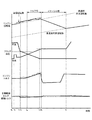
上記の図2に示す制御を行った場合のエンジン回転数Ne、各クラッチC1,C2の油圧(もしくはその指令値:以下、油圧と記す。)、エンジントルクTe、駆動トルクの各変化を図3にタイムチャートで模式的に示してある。図3において、アップシフトの判断が成立したt0時点では、解放側クラッチC1の油圧が高くなっていて解放側クラッチC1が係合し、係合側クラッチC2の油圧が「0」になっていて係合側クラッチC2が解放している。その直後のt1時点に係合側クラッチC2に対するファーストフィル制御が実行される。ファーストフィル制御は、係合側クラッチC2に生じているクリアランス(パッククリアランスと称されることがある。)を詰めるための制御であって、油圧が一時的に高められる。 FIG. 3 shows changes in the engine speed Ne, the hydraulic pressures of the clutches C1 and C2 (or their command values: hereinafter referred to as hydraulic pressure), engine torque Te, and driving torque when the control shown in FIG. 2 is performed. Is schematically shown in the time chart. 3, the t 0 when the upshift determination is satisfied, engaged releasing clutch C1 and has a higher hydraulic pressure of the disengagement side clutch C1, the hydraulic pressure of the on-coming clutch C2 has become "0" Thus, the engagement side clutch C2 is released. Fast fill control is executed with respect to the engagement side clutch C2 to time point t 1 immediately thereafter. The first fill control is a control for closing a clearance (sometimes referred to as a pack clearance) generated in the engagement side clutch C2, and the hydraulic pressure is temporarily increased.
ファーストフィルの後、係合側クラッチC2の油圧は、パッククリアランスが開かない程度の定圧(低圧)に維持され、その過程で解放側クラッチC1の油圧が、ドライバーの要求駆動力を伝達できる最低トルクを設定する圧力に低下させられる(t2時点)。これに続けて解放側クラッチC1の油圧がスイープダウンされる。解放側クラッチC1の油圧が低下することにより伝達トルク容量が低下するので、解放側クラッチC1に滑りが生じてエンジン回転数Neが変速前の同期回転数より増大する(t3時点)。すなわち、エンジン回転数Neの吹き上がりが生じる。これは、前述した図2に示すフローチャートにおけるステップS4で肯定的判断された状態である。したがって、エンジン回転数Neの吹き上がりと同時に、あるいはエンジン回転数Neの吹き上がりに続けて、係合側クラッチC2のトルクが演算され、その演算結果に応じた油圧が係合側クラッチC2に供給される。その結果、係合側クラッチC2の油圧(伝達トルク容量)が次第に増大する。 After the first fill, the hydraulic pressure of the engagement side clutch C2 is maintained at a constant pressure (low pressure) that does not open the pack clearance, and in this process, the hydraulic pressure of the release side clutch C1 is the minimum torque that can transmit the driver's requested driving force. Is reduced to a pressure setting (at time t 2 ). Following this, the hydraulic pressure of the release side clutch C1 is swept down. Since the oil pressure of the disengagement side clutch C1 is transmitted torque capacity is reduced by reducing the engine speed Ne and slip occurs in the release-side clutch C1 is increased than the synchronous speed of the pre-shift (t 3 time points). That is, the engine speed Ne is increased. This is a state in which an affirmative determination is made in step S4 in the flowchart shown in FIG. Accordingly, the torque of the engagement side clutch C2 is calculated simultaneously with the increase of the engine speed Ne or continuously with the increase of the engine speed Ne, and the hydraulic pressure corresponding to the calculation result is supplied to the engagement side clutch C2. Is done. As a result, the hydraulic pressure (transmission torque capacity) of the engagement side clutch C2 gradually increases.
また、エンジン回転数Neについて、変速前の同期回転数に予め定めた所定のスリップ回転数を加えた回転数が目標回転数として設定され、実際のエンジン回転数Neがその目標回転数に一致するようにエンジントルクTeがFB制御される。なお、スリップ回転数は、搭乗者がエンジン回転数Neの意図しない吹き上がりを感じ取ったり、違和感を抱いたりすることがない程度の回転数として予め定められる。したがって、エンジントルクは図3に示すように、運動方程式に基づいて算出されたトルク(実線で示すトルク)よりも大きいトルク(破線で示すトルク)になる。このトルク制御は、エンジン1のスロットル開度や点火時期を制御することにより行うことができる。 For the engine speed Ne, a rotational speed obtained by adding a predetermined slip rotational speed to the synchronous rotational speed before shifting is set as the target rotational speed, and the actual engine rotational speed Ne matches the target rotational speed. Thus, the engine torque Te is FB-controlled. The slip rotation speed is determined in advance as a rotation speed that does not cause the passenger to feel an unintentional increase in the engine rotation speed Ne or feel uncomfortable. Therefore, as shown in FIG. 3, the engine torque becomes a torque (torque indicated by a broken line) larger than the torque calculated based on the equation of motion (torque indicated by a solid line). This torque control can be performed by controlling the throttle opening and ignition timing of the engine 1.
スイープダウン制御されて低下する解放側クラッチC1の油圧に応じて、係合側クラッチC2の油圧が次第に増大させられる。すなわち、解放側クラッチC1の伝達トルク容量の低下に従って、係合側クラッチC2の伝達トルク容量が次第に増大させられる。その結果、解放側クラッチC1が受け持っていたトルクの一部を係合側クラッチC2が受け持つようになり、トルク相が開始する(t4時点)。その後、受け持つトルクの大小の関係が次第に逆転する。このようなクラッチ・ツウ・クラッチ変速において、トルクを受け持つクラッチを変更する制御がクラッチの架け替えと称される制御である。 The hydraulic pressure of the engagement side clutch C2 is gradually increased in accordance with the hydraulic pressure of the release side clutch C1 that decreases as a result of the sweep-down control. That is, as the transmission torque capacity of the release side clutch C1 decreases, the transmission torque capacity of the engagement side clutch C2 is gradually increased. As a result, a part of the torque releasing clutch C1 was in charge now responsible engagement side clutch C2, torque phase begins (t 4 time). Thereafter, the magnitude relationship between the torques that are handled gradually reverses. In such clutch-to-clutch shifting, control for changing the clutch responsible for torque is control referred to as clutch replacement.
このクラッチの架け替えを行っている過程では、クラッチトルクやエンジントルクのバラツキが原因で駆動トルクが落ち込み易い。しかしながら、本発明の実施形態での変速制御装置では、エンジン回転数Neを同期回転数より高い回転数に維持するように、エンジントルクTeのFB制御を行うので、クラッチトルクやエンジントルクTeのバラツキの影響を少なくして駆動トルクの落ち込みを抑制することができる。すなわち、エンジントルクTeは、同期回転数を維持するトルクより大きいトルクに制御することになるので、エンジントルクにバラツキがあっても駆動トルクが大きく低下することを回避できる。一方、クラッチトルクのバラツキによって解放側クラッチC1と係合側クラッチC2とが共に大きいトルクを持つ状態(タイアップ状態)の傾向が強くなった場合、自動変速機2としてはいわゆる内部ロック傾向になって出力軸トルクが低下するが、上記のようにエンジントルクTeが同期回転数より高い回転数を維持するトルクに制御されているので、駆動トルク(出力軸トルク)の低下を抑制することができる。これとは反対にクラッチトルクのバラツキによって解放側クラッチC1と係合側クラッチC2との伝達トルク容量が共に低下傾向になってエンジン回転数Neが吹き上がりやすい状態になった場合、エンジントルクTeは、実回転数と同期回転数との差が前述したスリップ回転数になるように制御されるので、クラッチC1,C2での滑りを抑制して目標駆動トルクに近い駆動トルクを設定することができる。結局、図2を参照して説明した制御を行うように構成された本発明の実施態様による変速制御装置によれば、クラッチ・ツウ・クラッチ変速であるアップシフト際のトルク相で駆動トルクが落ち込むことを防止もしくは抑制することができる。
In the process of changing the clutch, the driving torque tends to drop due to variations in clutch torque and engine torque. However, in the speed change control device according to the embodiment of the present invention, the FB control of the engine torque Te is performed so that the engine speed Ne is maintained at a higher speed than the synchronous speed, so that the clutch torque and the engine torque Te vary. The influence of this can be reduced, and the fall of drive torque can be suppressed. That is, since the engine torque Te is controlled to a torque larger than the torque that maintains the synchronous rotation speed, it is possible to avoid the drive torque from greatly decreasing even if the engine torque varies. On the other hand, when the tendency of the state where the release side clutch C1 and the engagement side clutch C2 both have large torque (tie-up state) becomes strong due to the variation of the clutch torque, the
スイープダウンされる解放側クラッチC1の油圧(伝達トルク容量)が「0」になるなど、所定値以下の圧力に達すると(t5時点)、前述した運動方程式に基づくエンジントルクTeや係合側クラッチC2のトルクの制御が終了され、エンジントルクTeはその時点のトルクに維持される。また、係合側クラッチC2の油圧(伝達トルク容量)はその時点以前での増加勾配をもって増大させられる。従って、係合側クラッチC2の伝達トルク容量が十分に大きくなるので、エンジントルクTeや伝達トルク容量などにバラツキがあっても駆動トルクが落ち込んだりショックが生じたりすることが回避もしくは抑制される。 A hydraulic release side clutch C1 that is swept down (transmission torque capacity) becomes "0", and reaches a predetermined value below the pressure (t 5 point), the engine torque Te and the engagement side based on the equation of motion described above The control of the torque of the clutch C2 is terminated, and the engine torque Te is maintained at the current torque. Further, the hydraulic pressure (transmission torque capacity) of the engagement side clutch C2 is increased with an increasing gradient before that time. Accordingly, since the transmission torque capacity of the engagement side clutch C2 becomes sufficiently large, it is avoided or suppressed that the drive torque falls or a shock occurs even if the engine torque Te, the transmission torque capacity, etc. vary.
解放側クラッチC1の油圧が実質的に「0」になり、かつ係合側クラッチC2の油圧が十分に大きなることにより、エンジン1を含むパワートレーンにおける回転部材の回転数が変速後の変速段での変速比に応じた回転数(変速後同期回転数)に向けて変化し始める。そのような回転数の変化に基づいてイナーシャ相の開始が判定される(t6時点)。イナーシャ相の開始によって係合側クラッチC2の油圧がその時点の油圧に維持される。また、エンジントルクTeはイナーシャ相での制御のために、低下させられる。このエンジントルクTeの低下制御は、例えば点火時期を遅角することにより実行される。さらに、アップシフトでのイナーシャ相では、回転数の低下に伴う運動エネルギーの放出によって駆動トルクが目標駆動トルクよりも僅かに大きくなる。そして、エンジン回転数Neが変速後同期回転数に達することによりアップシフトが終了し(t7時点)、係合側クラッチC2の油圧は、例えば油圧制御部10におけるライン圧に相当する圧力に向けて増大させられる。
When the hydraulic pressure of the disengagement side clutch C1 is substantially “0” and the hydraulic pressure of the engagement side clutch C2 is sufficiently large, the rotational speed of the rotating member in the power train including the engine 1 is changed to the speed stage after the shift. It starts to change toward the rotation speed (synchronous rotation speed after shifting) according to the gear ratio at. Start of the inertia phase is determined on the basis of such rotational speed variation (t 6 time). With the start of the inertia phase, the hydraulic pressure of the engagement side clutch C2 is maintained at the current hydraulic pressure. Further, the engine torque Te is reduced for control in the inertia phase. The engine torque Te reduction control is executed, for example, by retarding the ignition timing. Further, in the inertia phase in the upshift, the drive torque becomes slightly larger than the target drive torque due to the release of kinetic energy accompanying the decrease in the rotational speed. Then, the upshift is completed by the engine rotational speed Ne reaches the post-shift synchronous speed (t 7 point), the oil pressure of the engaging clutch C2, for example toward the pressure corresponding to the line pressure in the
1…エンジン(内燃機関)、 2…自動変速機、 C1…クラッチ、 C2…クラッチ、 3…プロペラシャフト、 4…デファレンシャルギヤ、 5…車軸、 6…駆動輪、 7…電子制御装置(E−ECU)、 8…車速センサ、 9…アクセル開度センサ、 10…油圧制御部、 11…電子制御装置(T−ECU)。 DESCRIPTION OF SYMBOLS 1 ... Engine (internal combustion engine), 2 ... Automatic transmission, C1 ... Clutch, C2 ... Clutch, 3 ... Propeller shaft, 4 ... Differential gear, 5 ... Axle, 6 ... Drive wheel, 7 ... Electronic control unit (E-ECU) 8) Vehicle speed sensor, 9 ... Accelerator opening sensor, 10 ... Hydraulic control unit, 11 ... Electronic control unit (T-ECU).
Claims (3)
前記アップシフトの際に前記第1摩擦係合機構と前記第2摩擦係合機構と前記エンジンとを制御するコントローラを有し、
前記コントローラは、
前記アップシフトの際に前記第1摩擦係合機構の伝達トルク容量を予め定めた勾配で低下させるとともに、前記第1摩擦係合機構の伝達トルク容量の低下に従って前記第2摩擦係合機構の伝達トルク容量を増大させ、
前記第1摩擦係合機構の伝達トルク容量を低下させるとともに前記第2摩擦係合機構の伝達トルク容量を増大させているトルク相において、前記低速側の変速段での前記エンジンの同期回転数より予め定めた所定回転数高い回転数を前記エンジンの目標回転数として設定し、
前記トルク相において前記エンジンの回転数を前記目標回転数に一致させるように前記エンジンのトルクを、前記エンジンの回転数と前記目標回転数との偏差に基づいてフィードバック制御する
ように構成されていることを特徴とする自動変速機の変速制御装置。 An automatic transmission having a first friction engagement mechanism engaged at a low speed shift stage and a second friction engagement mechanism engaged at a high speed shift stage having a speed ratio smaller than that of the low speed shift stage. The machine is connected to the output side of the engine, and the up-shift is performed by releasing the first friction engagement mechanism and engaging the second friction engagement mechanism with the engine outputting torque. In a transmission control device for a transmission,
A controller for controlling the first friction engagement mechanism, the second friction engagement mechanism, and the engine during the upshift;
The controller is
During the upshift, the transmission torque capacity of the first friction engagement mechanism is decreased with a predetermined gradient, and the transmission of the second friction engagement mechanism is performed according to the decrease of the transmission torque capacity of the first friction engagement mechanism. Increase torque capacity,
In the torque phase in which the transmission torque capacity of the first friction engagement mechanism is decreased and the transmission torque capacity of the second friction engagement mechanism is increased, the synchronous rotational speed of the engine at the low speed side shift stage A predetermined higher rotational speed is set as a target rotational speed of the engine,
The engine torque is feedback-controlled based on a deviation between the engine speed and the target speed so that the engine speed matches the target speed in the torque phase. A shift control apparatus for an automatic transmission.
前記コントローラは、
前記自動変速機の出力軸トルクと前記自動変速機の入力トルクと前記第1摩擦係合機構のトルクと前記第2摩擦係合機構のトルクとの関係を定めている運動方程式と、前記自動変速機の入力回転数の変化率と前記自動変速機の入力トルクと前記第1摩擦係合機構のトルクと前記第2摩擦係合機構のトルクとの関係を定めている運動方程式とを使用し、かつ前記出力軸トルクを一定値とするとともに前記入力回転数の変化率を前記アップシフト開始前の値にして前記エンジンのトルクと前記第2摩擦係合機構のトルクとを算出し、
前記フィードバック制御は、前記運動方程式から算出されたトルクを補正する制御である
ことを特徴とする自動変速機の変速制御装置。 The shift control apparatus for an automatic transmission according to claim 1,
The controller is
An equation of motion defining a relationship among an output shaft torque of the automatic transmission, an input torque of the automatic transmission, a torque of the first friction engagement mechanism, and a torque of the second friction engagement mechanism, and the automatic transmission Using the rate of change of the input rotational speed of the machine, the input torque of the automatic transmission, the equation of motion defining the relationship between the torque of the first friction engagement mechanism and the torque of the second friction engagement mechanism, And calculating the torque of the engine and the torque of the second friction engagement mechanism by setting the output shaft torque to a constant value and setting the rate of change of the input rotational speed to a value before the start of the upshift.
The shift control device for an automatic transmission, wherein the feedback control is a control for correcting a torque calculated from the equation of motion.
前記コントローラは、
前記第1摩擦係合機構の伝達トルク容量が予め定めた所定値以下に低下して前記第1摩擦係合機構が解放状態になった場合に、前記エンジンのトルクを前記第1摩擦係合機構が解放状態になった際のトルクに保持し、かつ前記第2摩擦係合機構の伝達トルク容量を前記第1摩擦係合機構が解放状態になった際の伝達トルク容量の増大率で増大させるように構成されている
ことを特徴とする自動変速機の変速制御装置。 The shift control device for an automatic transmission according to claim 1 or 2,
The controller is
When the transmission torque capacity of the first friction engagement mechanism drops below a predetermined value and the first friction engagement mechanism is released, the torque of the engine is reduced to the first friction engagement mechanism. Is maintained at the torque when the first friction engagement mechanism is released, and the transmission torque capacity of the second friction engagement mechanism is increased at the rate of increase of the transmission torque capacity when the first friction engagement mechanism is released. A shift control device for an automatic transmission, characterized in that it is configured as described above.
Priority Applications (3)
| Application Number | Priority Date | Filing Date | Title |
|---|---|---|---|
| JP2015226288A JP6288048B2 (en) | 2015-11-19 | 2015-11-19 | Shift control device for automatic transmission |
| DE102016120396.3A DE102016120396B4 (en) | 2015-11-19 | 2016-10-26 | Shift control system for an automatic transmission |
| US15/337,284 US9994224B2 (en) | 2015-11-19 | 2016-10-28 | Shift control system for automatic transmission |
Applications Claiming Priority (1)
| Application Number | Priority Date | Filing Date | Title |
|---|---|---|---|
| JP2015226288A JP6288048B2 (en) | 2015-11-19 | 2015-11-19 | Shift control device for automatic transmission |
Publications (2)
| Publication Number | Publication Date |
|---|---|
| JP2017094785A JP2017094785A (en) | 2017-06-01 |
| JP6288048B2 true JP6288048B2 (en) | 2018-03-07 |
Family
ID=58693983
Family Applications (1)
| Application Number | Title | Priority Date | Filing Date |
|---|---|---|---|
| JP2015226288A Active JP6288048B2 (en) | 2015-11-19 | 2015-11-19 | Shift control device for automatic transmission |
Country Status (3)
| Country | Link |
|---|---|
| US (1) | US9994224B2 (en) |
| JP (1) | JP6288048B2 (en) |
| DE (1) | DE102016120396B4 (en) |
Families Citing this family (7)
| Publication number | Priority date | Publication date | Assignee | Title |
|---|---|---|---|---|
| DE102019200535A1 (en) * | 2019-01-17 | 2020-07-23 | Zf Friedrichshafen Ag | Method and control unit for operating a power shift transmission |
| CN112855921B (en) * | 2019-11-12 | 2022-08-02 | 纬湃汽车电子(长春)有限公司 | Method for controlling a shifting process of an automatic transmission, motor vehicle |
| WO2021182601A1 (en) * | 2020-03-12 | 2021-09-16 | アイシン・エィ・ダブリュ株式会社 | Control device |
| CN114909466B (en) * | 2021-02-07 | 2024-03-29 | 广汽埃安新能源汽车有限公司 | A vehicle downshift control method, device and storage medium |
| CN114312729B (en) * | 2021-12-29 | 2024-05-17 | 潍柴动力股份有限公司 | Internal friction torque compensation method and device based on non-separable gear shifting |
| CN114992322B (en) * | 2022-05-25 | 2024-03-01 | 合肥工业大学 | A vehicle power upshift optimization control method |
| KR102872172B1 (en) * | 2022-12-15 | 2025-10-15 | 현대트랜시스 주식회사 | Vehicle engine control apparatus and method |
Family Cites Families (20)
| Publication number | Priority date | Publication date | Assignee | Title |
|---|---|---|---|---|
| US4792902A (en) * | 1985-12-12 | 1988-12-20 | Ford Motor Company | Engine ignition timing for a clutch engagement control system |
| JP3528712B2 (en) | 1999-10-25 | 2004-05-24 | アイシン・エィ・ダブリュ株式会社 | Automotive gear change control device |
| EP1485270A2 (en) | 2002-03-07 | 2004-12-15 | LuK Lamellen und Kupplungsbau Beteiligungs KG | Method for carrying out gear shifting in a twin-clutch gearbox |
| JP4295962B2 (en) * | 2002-07-29 | 2009-07-15 | アイシン精機株式会社 | Shift control device for automatic transmission |
| EP1507103B1 (en) * | 2003-08-14 | 2006-04-05 | Getrag Ford Transmissions GmbH | Method for shifting dual clutches |
| US7351183B2 (en) * | 2004-12-16 | 2008-04-01 | Ford Global Technologies, Llc | Ratio shift control for a multiple ratio automatic transmission |
| JP2007239832A (en) | 2006-03-07 | 2007-09-20 | Hitachi Ltd | Vehicle control apparatus and vehicle control method |
| JP4821409B2 (en) * | 2006-03-31 | 2011-11-24 | アイシン・エィ・ダブリュ株式会社 | Hydraulic control device for automatic transmission |
| JP2010115983A (en) | 2008-11-11 | 2010-05-27 | Toyota Motor Corp | Controller for vehicle power transmission |
| US8079936B2 (en) * | 2009-04-09 | 2011-12-20 | Ford Global Technologies, Llc | Gear shift control of a dual clutch transmission |
| JP5207080B2 (en) | 2009-10-30 | 2013-06-12 | アイシン・エィ・ダブリュ株式会社 | Vehicle control device |
| US8565990B2 (en) * | 2009-11-13 | 2013-10-22 | Ford Global Technologies, Llc. | Vehicle and method for controlling engine start in a vehicle |
| US8682545B2 (en) * | 2010-06-15 | 2014-03-25 | Ford Global Technologies, Llc | Damping oscillations during a gear ratio change of a dual clutch powershift transmission |
| JP5532339B2 (en) * | 2011-03-09 | 2014-06-25 | アイシン・エィ・ダブリュ株式会社 | Control device |
| US8775044B2 (en) | 2011-06-08 | 2014-07-08 | Ford Global Technologies, Llc | Clutch torque trajectory correction to provide torque hole filling during a ratio upshift |
| JP2013245590A (en) * | 2012-05-24 | 2013-12-09 | Toyota Motor Corp | Vehicle transmission control system |
| US9365206B2 (en) * | 2013-07-17 | 2016-06-14 | Eaton Corporation | Method for non-microslip based dual clutch transmission power on up shift |
| US9056613B2 (en) * | 2013-11-06 | 2015-06-16 | Ford Global Technologies, Llc | System and method for upshift torque modification using an upstream clutch in a hybrid vehicle |
| JP2015226288A (en) | 2014-05-29 | 2015-12-14 | 住友電気工業株式会社 | COMMUNICATION SYSTEM, SOLAR POWER GENERATION MONITORING SYSTEM, COMMUNICATION METHOD, AND COMPUTER PROGRAM |
| US9162680B1 (en) * | 2014-06-10 | 2015-10-20 | Ford Global Technologies, Llc | Method of controlling automatic transmission coasting downshift |
-
2015
- 2015-11-19 JP JP2015226288A patent/JP6288048B2/en active Active
-
2016
- 2016-10-26 DE DE102016120396.3A patent/DE102016120396B4/en active Active
- 2016-10-28 US US15/337,284 patent/US9994224B2/en active Active
Also Published As
| Publication number | Publication date |
|---|---|
| DE102016120396A1 (en) | 2017-05-24 |
| US9994224B2 (en) | 2018-06-12 |
| JP2017094785A (en) | 2017-06-01 |
| US20170144667A1 (en) | 2017-05-25 |
| DE102016120396B4 (en) | 2022-08-11 |
Similar Documents
| Publication | Publication Date | Title |
|---|---|---|
| JP6288048B2 (en) | Shift control device for automatic transmission | |
| JP5928580B2 (en) | Vehicle shift control device | |
| KR20150036390A (en) | Vehicle transmission controller | |
| US9188220B2 (en) | Gear shift control apparatus for vehicle | |
| US10508736B2 (en) | Upshift control method for DCT vehicle | |
| JP5724966B2 (en) | Vehicle shift control device | |
| JP6304094B2 (en) | Control device for lock-up clutch | |
| JP2013245590A (en) | Vehicle transmission control system | |
| JP5991165B2 (en) | Vehicle shift control device | |
| JP5928579B2 (en) | Vehicle shift control device | |
| JP2018100731A (en) | Vehicle shift control device | |
| WO2014076822A1 (en) | Vehicle transmission control device | |
| JP2017155900A (en) | Shift control device for automatic transmission | |
| JPWO2013145970A1 (en) | Automatic transmission and control method thereof | |
| JP4165591B2 (en) | Vehicle control device | |
| JP2017094951A (en) | Shift control device for automatic transmission | |
| JP5103833B2 (en) | Vehicle control device, control method, program for causing computer to execute the control method, and recording medium recording program | |
| JP6536424B2 (en) | Transmission control device for automatic transmission | |
| CN107664211A (en) | The control device of automatic transmission | |
| US10487939B2 (en) | Control device of automatic transmission for vehicle | |
| JP2015220970A (en) | Electric vehicle controller | |
| JP7806612B2 (en) | Vehicle transmission control device | |
| JP2017166537A (en) | Control device of automatic transmission | |
| JP2019211027A (en) | Vehicular controller and vehicular control method | |
| JP2008064156A (en) | Control device for automatic transmission |
Legal Events
| Date | Code | Title | Description |
|---|---|---|---|
| A621 | Written request for application examination |
Free format text: JAPANESE INTERMEDIATE CODE: A621 Effective date: 20170321 |
|
| TRDD | Decision of grant or rejection written | ||
| A977 | Report on retrieval |
Free format text: JAPANESE INTERMEDIATE CODE: A971007 Effective date: 20171227 |
|
| A01 | Written decision to grant a patent or to grant a registration (utility model) |
Free format text: JAPANESE INTERMEDIATE CODE: A01 Effective date: 20180109 |
|
| A61 | First payment of annual fees (during grant procedure) |
Free format text: JAPANESE INTERMEDIATE CODE: A61 Effective date: 20180122 |
|
| R151 | Written notification of patent or utility model registration |
Ref document number: 6288048 Country of ref document: JP Free format text: JAPANESE INTERMEDIATE CODE: R151 |