JP6292844B2 - Heat exchanger - Google Patents
Heat exchanger Download PDFInfo
- Publication number
- JP6292844B2 JP6292844B2 JP2013243428A JP2013243428A JP6292844B2 JP 6292844 B2 JP6292844 B2 JP 6292844B2 JP 2013243428 A JP2013243428 A JP 2013243428A JP 2013243428 A JP2013243428 A JP 2013243428A JP 6292844 B2 JP6292844 B2 JP 6292844B2
- Authority
- JP
- Japan
- Prior art keywords
- plate
- flat tube
- opening
- longitudinal direction
- openings
- Prior art date
- Legal status (The legal status is an assumption and is not a legal conclusion. Google has not performed a legal analysis and makes no representation as to the accuracy of the status listed.)
- Active
Links
- 239000012530 fluid Substances 0.000 claims description 22
- 239000003921 oil Substances 0.000 description 80
- 239000000498 cooling water Substances 0.000 description 21
- 238000005219 brazing Methods 0.000 description 8
- 230000002093 peripheral effect Effects 0.000 description 8
- 239000000463 material Substances 0.000 description 7
- 230000003014 reinforcing effect Effects 0.000 description 5
- 230000036544 posture Effects 0.000 description 3
- XEEYBQQBJWHFJM-UHFFFAOYSA-N Iron Chemical compound [Fe] XEEYBQQBJWHFJM-UHFFFAOYSA-N 0.000 description 2
- 239000002826 coolant Substances 0.000 description 2
- 238000010030 laminating Methods 0.000 description 2
- 230000015572 biosynthetic process Effects 0.000 description 1
- 210000000078 claw Anatomy 0.000 description 1
- 239000011248 coating agent Substances 0.000 description 1
- 238000000576 coating method Methods 0.000 description 1
- 238000001816 cooling Methods 0.000 description 1
- 238000010438 heat treatment Methods 0.000 description 1
- 229910052742 iron Inorganic materials 0.000 description 1
- 239000010687 lubricating oil Substances 0.000 description 1
- 239000002184 metal Substances 0.000 description 1
- 229910052751 metal Inorganic materials 0.000 description 1
- 229910001220 stainless steel Inorganic materials 0.000 description 1
- 239000010935 stainless steel Substances 0.000 description 1
- XLYOFNOQVPJJNP-UHFFFAOYSA-N water Substances O XLYOFNOQVPJJNP-UHFFFAOYSA-N 0.000 description 1
Images




Landscapes
- Details Of Heat-Exchange And Heat-Transfer (AREA)
- Heat-Exchange Devices With Radiators And Conduit Assemblies (AREA)
Description
この発明は、第1の流体の流路となる偏平チューブを複数段積層し、各偏平チューブの間に第2の流体の流路となる間隙を確保してなるいわゆる多板式の熱交換器の改良に関する。 The present invention relates to a so-called multi-plate heat exchanger in which a plurality of flat tubes serving as flow paths for the first fluid are stacked and a gap serving as a flow path for the second fluid is secured between the flat tubes. Regarding improvement.
いわゆる多板式の熱交換器として、特許文献1に記載されているように、例えば長円形をなす第1のプレートと第2のプレートとをその周縁において互いに接合することで内部にオイル流路を形成した偏平チューブを構成し、かつ複数の偏平チューブを、個々の偏平チューブの間に冷却水流路となる間隙が生じるように複数段積層してなるオイルクーラが知られている。この種のオイルクーラは、例えば大型エンジンのシリンダブロックなどに設けられるケース内に収容した形で用いられるものであり、ケース内にエンジンの冷却水が強制循環される一方、オイルクーラ内にオイルが圧送され、両者の熱交換によってオイルの冷却が行われる。
As a so-called multi-plate heat exchanger, as described in
第1のプレートおよび第2のプレートは、例えばこれらをいわゆるクラッド材から構成することで、炉内での加熱によるろう付けによって、間にフィンプレートを挟んだ状態で互いに接合される。つまり、第1のプレートの周縁と第2のプレートの周縁とが互いに突き合わされ、かつろう付けされており、また、オイル流路となる内部では、フィンプレートの上下両面に第1のプレートと第2のプレートとがそれぞれろう付けされている。 The first plate and the second plate are made of a so-called clad material, for example, and are joined to each other with the fin plate sandwiched therebetween by brazing by heating in a furnace. That is, the peripheral edge of the first plate and the peripheral edge of the second plate are abutted and brazed to each other, and the first plate and the second plate are disposed on both upper and lower surfaces of the fin plate inside the oil passage. Each of the two plates is brazed.
そして、各段の偏平チューブの間においては、各プレートのオイル入口およびオイル出口となる開口部の周縁を一方のプレートにおいてボス状に一段高く形成し、これを順次接続していくことによって、積層方向に連続したオイル入口通路およびオイル出口通路が構成され、これによって各偏平チューブ内部のオイル流路が互いに連通している。上記のオイル入口通路およびオイル出口通路は、オイルクーラの取付フランジに設けられたオイル入口およびオイル出口にそれぞれ接続される。 Then, between the flat tubes of each stage, the peripheral edge of the opening serving as the oil inlet and oil outlet of each plate is formed one step higher in a boss shape on one plate, and this is sequentially connected to form a stack. An oil inlet passage and an oil outlet passage that are continuous in the direction are formed, whereby the oil passages in the respective flat tubes communicate with each other. The oil inlet passage and the oil outlet passage are respectively connected to an oil inlet and an oil outlet provided in a mounting flange of the oil cooler.
上記のような従来の熱交換器においては、各偏平チューブがある程度の幅を有するのに対し、該偏平チューブの端部に設けられる開口部がそれぞれ1個であるため、各偏平チューブ内での流体の流れの分布としては、各偏平チューブの入口となる一端部の開口部から出口となる他端部の開口部へと偏平チューブの中央部分のみを直線的に流れる傾向がある。従って、偏平チューブの幅の全体を熱交換に有効利用することができず、熱交換効率の点で改善の余地がある。 In the conventional heat exchanger as described above, each flat tube has a certain width, whereas there is one opening provided at the end of the flat tube. As a fluid flow distribution, there is a tendency that only the central portion of the flat tube flows linearly from the opening at one end serving as the inlet of each flat tube to the opening at the other end serving as the outlet. Therefore, the entire width of the flat tube cannot be effectively used for heat exchange, and there is room for improvement in terms of heat exchange efficiency.
また、仮に偏平チューブの各端部に複数個の開口部を設けるようにした場合、一般に単一の開口部となるオイルの入口ないし出口と接続するためには、オイルの流れを分流もしくは合流させる別部材からなるコネクタが必要となり、構成が複雑になるとともに、オイル入口部ないし出口部が大型化する可能性がある。 Also, if a plurality of openings are provided at each end of the flat tube, the oil flow is divided or merged in order to connect to an oil inlet or outlet which is generally a single opening. A connector made of a separate member is required, the configuration becomes complicated, and the oil inlet or outlet may be enlarged.
この発明は、内部が第1の流体の流路となる偏平チューブが第2の流体の流路となる間隙を介して複数段積層されて構成された熱交換器であって、各偏平チューブは、周縁において互いに接合された第1のプレートおよび第2のプレートと、これらの第1のプレートおよび第2のプレートの間に挟持されたフィンプレートと、からなり、隣接する2つの偏平チューブが、一方の偏平チューブの第2のプレートの長手方向の各端部にそれぞれ設けられた開口部と他方の偏平チューブの第1のプレートの長手方向の各端部にそれぞれ設けられた開口部とが互いに接合されることで互いに連通しており、これらの開口部を介して各偏平チューブの長手方向に第1の流体が通流する熱交換器において、
最下段の偏平チューブにおける第1のプレートの長手方向の各端部には、上記開口部として、熱交換器の流体入口もしくは流体出口となる単一の開口部が形成されており、
この第1のプレートと組み合わされる第2のプレートの長手方向の各端部には、上記開口部として、一対の開口部が上記偏平チューブの幅方向に並んで配置されており、
上記第2のプレートにおける一対の開口部は、互いに隣接する部分の開口縁が偏平チューブ長手方向に沿った直線状をなすとともに、偏平チューブの長手方向中央に向かう部分の開口縁が、偏平チューブの幅方向に沿った直線状をなし、これら2つの直線状部分によって構成されるコーナー部が、積層方向に投影して見たときに、上記第1のプレートの単一の開口部内に位置している。
The present invention is a heat exchanger in which a flat tube whose inside is a flow path for a first fluid is stacked in a plurality of stages via a gap which is a flow path for a second fluid, A first plate and a second plate joined to each other at the periphery, and a fin plate sandwiched between the first plate and the second plate, and two adjacent flat tubes, An opening provided at each end in the longitudinal direction of the second plate of one flat tube and an opening provided at each end in the longitudinal direction of the first plate of the other flat tube are mutually connected. In the heat exchanger in which the first fluid flows in the longitudinal direction of each flat tube through these openings, which are communicated with each other by being joined,
At each end in the longitudinal direction of the first plate in the lowermost flat tube, a single opening serving as a fluid inlet or a fluid outlet of the heat exchanger is formed as the opening.
At each end in the longitudinal direction of the second plate combined with the first plate, as the opening, a pair of openings are arranged side by side in the width direction of the flat tube,
The pair of openings in the second plate are such that the opening edges of the adjacent portions form a straight line along the longitudinal direction of the flat tube, and the opening edges of the portion toward the longitudinal center of the flat tube are A straight line along the width direction is formed, and a corner portion constituted by these two straight line portions is located in a single opening of the first plate when projected in the stacking direction. Yes.
上記のように構成された熱交換器においては、オイル等の第1の流体が流れる機器側の最下段の偏平チューブにおいては、単一の開口部を通して第1の流体が流入する。流入した第1の流体の一部は、この最下段の偏平チューブを長手方向に流れ、他端部の単一の開口部から機器側へ流出する。また流入した第1の流体の他の一部は、第2のプレートの開口部を通して2段目の偏平チューブ内へ流入する。このとき、第2のプレートおよび対応する2段目の偏平チューブでは、偏平チューブの幅方向に拡がって配置された一対の開口部が存在し、しかも他端部にも出口となる一対の開口部が存在するので、偏平チューブ内を幅方向に広く拡がって第1の流体が流れる。従って、偏平チューブの幅方向の全体でより効率よく熱交換が行われる。 In the heat exchanger configured as described above, the first fluid flows through a single opening in the lowermost flat tube on the equipment side through which the first fluid such as oil flows. Part of the inflowing first fluid flows in the longitudinal direction in the lowermost flat tube and flows out from the single opening at the other end to the device side. The other part of the first fluid that has flowed in flows into the second-stage flat tube through the opening of the second plate. At this time, in the second plate and the corresponding second-stage flat tube, there is a pair of openings arranged in the width direction of the flat tube, and a pair of openings serving as outlets at the other end. Therefore, the first fluid flows in the flat tube with widening in the width direction. Therefore, heat exchange is performed more efficiently in the entire width direction of the flat tube.
すなわち、この発明では、最下段の偏平チューブの内部で、単一の開口部から一対の開口部への流れの分流もしくは一対の開口部から単一の開口部への流れの合流がなされ、別部材からなるコネクタ等が不要である。 That is, according to the present invention, the flow from the single opening to the pair of openings is divided or the flow from the pair of openings to the single opening is merged inside the lowermost flat tube. There is no need for a connector made of members.
ここで、第1のプレートの単一の開口部と第2のプレートの一対の開口部とを偏平チューブの積層方向に投影したときの両者の重なり具合によって、両者間での通路抵抗が左右される。両者が重なる面積が大きいほど、第1の流体が円滑に流れる。本発明では、第2のプレートの一対の開口部は非円形であり、偏平チューブの長手方向に沿った直線状の開口縁と偏平チューブの幅方向に沿った直線状の開口縁とによって構成されるコーナー部が、第2のプレートの単一の開口部内に位置している。従って、一対の開口部が円形である場合に比較して単一の開口部と重なる面積が大きくなり、第1の流体が円滑に流れる。 Here, when a single opening of the first plate and a pair of openings of the second plate are projected in the laminating direction of the flat tubes, the passage resistance between the two is influenced by the degree of overlap between the two. The The larger the area where both overlap, the more smoothly the first fluid flows. In the present invention, the pair of openings of the second plate are non-circular and are constituted by a linear opening edge along the longitudinal direction of the flat tube and a linear opening edge along the width direction of the flat tube. The corner is located within a single opening in the second plate. Therefore, compared with a case where the pair of openings are circular, the area overlapping with the single opening is increased, and the first fluid flows smoothly.
好ましい一つの態様では、上記一対の開口部の残りの部分が円弧形をなしている。 In a preferred embodiment, the remaining part of the pair of openings has an arc shape.
また、好ましい一つの態様では、上記フィンプレートの長手方向の端部が偏平チューブの幅方向に沿った直線状をなしており、一対の開口部の開口縁に沿って位置している。 Moreover, in one preferable aspect, the edge part of the longitudinal direction of the said fin plate has comprised the linear form along the width direction of a flat tube, and is located along the opening edge of a pair of opening part.
また、好ましい一つの態様では、2段目以降の偏平チューブが、上記の最下段の偏平チューブの第2のプレートに対応して一対の開口部を各端部に備えている。 In a preferred embodiment, the second and subsequent flat tubes are provided with a pair of openings at each end corresponding to the second plate of the lowermost flat tube.
この発明によれば、偏平チューブの幅方向に広く拡がった形で第1の流体を通流させることができ、通路抵抗の不必要な増加を伴わずに熱交換効率を向上させることができる。しかも、最下段の偏平チューブの内部で流れが幅方向に拡げられるので、機器と熱交換器との間の接続構造の複雑化や、熱交換器を含めた各部の大型化を招来することがない。 According to this invention, the first fluid can be allowed to flow in a form that is widened in the width direction of the flat tube, and the heat exchange efficiency can be improved without an unnecessary increase in passage resistance. Moreover, since the flow is expanded in the width direction inside the lowermost flat tube, the connection structure between the equipment and the heat exchanger may be complicated, and the size of each part including the heat exchanger may be increased. Absent.
また、第1のプレートにおける単一の開口部と第2のプレートにおける一対の開口部とが重なりあう面積を大きく確保でき、第1の流体の通路抵抗を低減することができる。 Further, it is possible to secure a large area where a single opening in the first plate overlaps with a pair of openings in the second plate, and to reduce the passage resistance of the first fluid.
以下、この発明の一実施例を図面に基づいて詳細に説明する。 Hereinafter, an embodiment of the present invention will be described in detail with reference to the drawings.
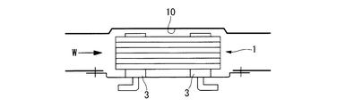
図1および図2は、この発明に係る熱交換器の一実施例として、多板式のオイルクーラ1を示している。このオイルクーラ1は、大型エンジンの潤滑油の冷却に用いられるもので、内部がオイル流路11(図6参照)となる偏平チューブ2が複数段積層され、各偏平チューブ2の間の間隙が冷却水流路12(図6参照)となる。なお、積層される偏平チューブ2の段数を変更することでオイルクーラ1としての熱交換容量を増減させることが可能であり、必要な熱交換容量に応じて偏平チューブ2の段数が設定される。このオイルクーラ1は、図3に示すように、冷却水(W)が長手方向に流れるケース10内に収容した状態で使用される。ケース10は、例えば、エンジンのシリンダブロックの一部に凹部として構成されたものであってもよく、あるいは、別個の独立した箱状のものであってもよい。
1 and 2 show a
図1および図2に示すように、オイルクーラ1は、複数の偏平チューブ2のほかに、オイルの入口および出口をそれぞれ構成する一対の取付フランジ3と、複数の偏平チューブ2を挟んで各取付フランジ3と対向するように配置された一対の補強プレート4と、を有する。なお、以下の説明では、理解を容易にするために、図1や図2に示す上下の姿勢を基準として、「上」「下」の用語を用いることとする。つまり取付フランジ3が位置する方をオイルクーラ1の下部と呼び、補強プレート4が位置する方をオイルクーラ1の上部と呼ぶこととするが、実際の車両におけるオイルクーラ1の搭載姿勢は任意であり、図1,図2のような姿勢に限定されるものではない。
As shown in FIGS. 1 and 2, the
上記偏平チューブ2は、その長手方向にオイルが流れるように全体として細長い帯状をなし、かつ両端部が緩く湾曲した略円弧形をなしている。この偏平チューブ2の長手方向の各端部に配置される上記取付フランジ3は、菱形ないし楕円形の比較的厚い板状をなし、エンジン側からのオイルの入口もしくは出口となる円形開口部6を中央に有し、かつ両端に一対の取付孔7を有する。また、補強プレート4は、偏平チューブ2の端部の円弧形状に対応した端縁形状を有し、比較的厚い板状をなしている。
The
図4および図5に示すように、1つの偏平チューブ2は、第1のプレートとなる下側プレート21と、第2のプレートとなる上側プレート22と、両者間に配置されるフィンプレート23と、の三者から構成される。これらの各プレート21,22,23および上記の取付フランジ3ならびに補強プレート4は、ステンレスや鉄等の金属板からなり、所定の状態に仮組み付けした後、炉内で加熱することにより、各部一体にろう付けされている。なお、プレート21,22,23等は、母材の表面にろう材をコーティングしてなるいわゆるクラッド材からなるが、ろう付け時に別体のろう材を用いるようにしてもよい。
As shown in FIGS. 4 and 5, one
各段の偏平チューブ2の下側プレート21は、図4に示す最下段の偏平チューブ2の下側プレート21Aを除き同一の構成であって、図5に示すように、上側プレート22との位置決めのために周縁が全周に亘ってフランジ31として僅かに立ち上がっているほかは、基本的に平坦な薄い板状をなしている。下側プレート21の長手方向の両端部には、それぞれ一対の略円形の開口部25が開口形成されており、この一対の開口部25は、下側プレート21の幅方向に並んで配置されている。上記開口部25の開口縁は、下方に位置する別の偏平チューブ2の上側プレート22との位置決めのために、下方へ向けて折り曲げられて、短い筒状部32として僅かに突出している。また、下側プレート21の長手方向両端には、下方へ円形のボス状に突出した端部突起部24が設けられている。この端部突起部24は、開口部25よりも長手方向の外側に位置し、かつ偏平チューブ2の幅方向については、一対の開口部25の間に位置している。
The
最下段の偏平チューブ2の下側プレート21Aにおいては、図4に示すように、長手方向の両端部に、それぞれ1つの円形の開口部25Aが開口形成されている。周縁には、他の段の下側プレート21と同様にフランジ31を備えている。この最下段の偏平チューブ2における開口部25Aは、それぞれ、一対の開口部25と部分的に重なるように、円の中心が偏平チューブ2の幅方向の中央に位置しており、かつ一対の開口部25の個々の開口面積よりも大きな開口面積を有する。そして、この開口部25Aは、取付フランジ3の円形開口部6に対応しており、開口部25Aの周縁が下方へ向けて折り曲げられて、短い円筒状の筒状部26を構成している。図1に示すように、この最下段の偏平チューブ2の下側プレート21Aの下面に取付フランジ3がろう付けされており、上記の筒状部26は、取付フランジ3の円形開口部6の内周に嵌合している。
In the
なお、開口部25Aの両側には、取付フランジ3の位置決めのための一対の係止爪26aが切り起こされている。また、図示例の最下段の下側プレート21Aは、炉内でのろう付け時に使用される図示せぬ治具との固着を回避するために、複数のエンボス27を備えている。
A pair of locking
各段の偏平チューブ2の上側プレート22は、図4,図5に示すように、周縁が全周に亘ってフランジ33として僅かに立ち上がっており、このフランジ33が下側プレート21(21A)のフランジ31の内側に密に嵌合するように、下側プレート21(21A)よりもごく僅か小さな外形状を有している。そして、下側プレート21の両端部の各一対の開口部25に対応して、上側プレート22の長手方向の各端部には、一対の略円形の開口部28が開口形成されている。そして、この開口部28の周囲は、上方へ向かって一段高くなるように折り曲げ形成されており、これにより、各開口部28を環状に囲むボス部29が形成されている。換言すれば、略円形のボス部29が上方へ突出形成され、その中央に開口部28が開口形成されている。
As shown in FIGS. 4 and 5, the
また、上側プレート22の長手方向中間部には、矩形のフィンプレート23が収容されるフィンプレート収容部30が上方へ向かって窪んだ形に形成されている。このフィンプレート収容部30は、フィンプレート23の矩形に対応した寸法の矩形状をなし、かつフィンプレート23の厚さに対応した深さを有している。これにより、上側プレート22は、周縁に下方へ向かった接合面22aが残存しかつ中央部がフィンプレート収容部30として窪んだ浅皿状をなしている。各端部の一対の開口部28は、上記フィンプレート収容部30の端部に隣接しており、ボス部29の内部空間がフィンプレート収容部30の内部空間と互いに連通している。換言すれば、母材の基準面からなる接合面22aに対しステップ状に窪んだ形状をなすフィンプレート収容部30の長手方向の端部が、ボス部29の内部空間に向かって開口している。そして、一対の開口部28の側方には、フランジ33の一部をさらに上方へ延長した形に、案内壁34が設けられている。この案内壁34は、図1にも示すように、偏平チューブ2の長手方向に沿った細長い帯状をなし、偏平チューブ2の積層方向(つまり上方)に突出している。
In addition, a fin
さらに、上記上側プレート22の長手方向の両端には、下側プレート21の端部突起部24に対応して、上方へ円形のボス状に突出した端部突起部35が設けられている。この端部突起部35は、開口部28を囲むボス部29よりも長手方向の外側に位置し、かつ偏平チューブ2の幅方向については、一対の開口部28の間に位置している。
Further,
また、フィンプレート収容部30の底壁となる長手方向中間部には、上方へ向けて円錐台形状ないし半球状に突出した多数のエンボス36が形成されている。このエンボス36の頂部は、開口部28周囲のボス部29頂面に一致する高さ位置にある。
In addition, a large number of
フィンプレート23は、図4,図5に示すように、外形が単純な矩形状をなしており、フィンプレート収容部30内に嵌合する大きさを有している。このフィンプレート23は、図7にその一部を拡大して示すように、1枚の母材に多数のスリットを設けて一定幅の多数の帯状片とし、かつこの帯状片を一定ピッチ毎に矩形ないしU字形に折り曲げてなるコルゲートフィンからなり、特に、隣接する帯状片のコルゲートの位置が互いに半ピッチずつずれたオフセット型コルゲートフィンからなる。なお、本発明においては、フィンプレート23の構成は、このオフセット型コルゲートフィンに限定されるものではない。
As shown in FIGS. 4 and 5, the
上記のように構成された下側プレート21(21A)と上側プレート22は、両者間にフィンプレート23を挟み込んだ状態で互いにろう付けにより接合される。つまり、下側プレート21(21A)のフランジ31の内側に上側プレート22のフランジ33が嵌合し、かつ上側プレート22周縁の接合面22aが下側プレート21の上面に重ね合わされて、互いにろう付けされる。従って、皿状に窪んだ形をなすフィンプレート収容部30は、平坦な下側プレート21(21A)によって覆われ、これにより、密閉されたオイル流路11が構成される。なお、フィンプレート23は、コルゲートフィンとして折曲されることで上下に間隔を有するものとなるが、その下面が下側プレート21にろう付けされ、かつ上面が上側プレート22にろう付けされる。
The lower plate 21 (21A) and the
そして、オイルクーラ1全体としては、前述したように複数の偏平チューブ2が互いに積層され、かつ一体にろう付けされている。このとき、ある段の偏平チューブ2における上側プレート22の開口部28周囲のボス部29は、その上に隣接する段の偏平チューブ2における下側プレート21の開口部25の周囲にろう付け接合され、同様に、上側プレート22のエンボス36頂部が下側プレート21の下面にろう付け接合される。さらに、両端に位置する端部突起部24,35同士が互いに突き合わされ、かつろう付け接合されている。これにより、ある段の上側プレート22とその上の段の下側プレート21との間に、冷却水流路12となる間隙が確保される一方、上側プレート22の開口部28と下側プレート21の開口部25とが互いに連通した状態に接続される。このように、複数の段に偏平チューブ2を積層した状態では、両者の開口部25,28とボス部29とから筒状のオイルポート37が構成され、このオイルポート37によって、各偏平チューブ2内のオイル流路11を互いに連通させる積層方向に連続した流路が形成される。この積層方向に連続したオイル流路の上端は、補強プレート4によって閉塞される。あるいは、最上段の偏平チューブ2における上側プレート22を、開口部28を具備しない構成のものとしてもよい。
As a whole, the
なお、ろう付け時には、下側プレート21の開口部25周縁の筒状部32が上側プレート22の開口部28内に嵌合することで、上の段の下側プレート21と下の段の上側プレート22とが互いに位置決めされる。
At the time of brazing, the
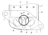
最下段の偏平チューブ2においては、図4に示すように、単一の開口部25Aを有する下側プレート21Aと一対の開口部28を有する上側プレート22とが組み合わされ、単一の開口部25Aの下面側に取付フランジ3が取り付けられる。図10は、この取付フランジ3の部分を下面側から図示したものであり、図示するように、単一の開口部25Aの中に一対の開口部28の一部が臨んでいる。そのため、オイルの入口側では単一の開口部25Aから流入したオイルが一対の開口部28へと分流し、オイルの出口側では一対の開口部28からのオイルが単一の開口部25Aへと合流して流れる。
In the lowermost
上記のようにろう付けにより一体に組み立てられたオイルクーラ1は、前述したように、冷却水が流れるケース10内に収容された状態で使用される(図3参照)。エンジン側のウォータポンプ(図示せず)により強制循環される冷却水(W)は、ケース10の長手方向に沿って流れる。オイルは、一方の取付フランジ3の円形開口部6を入口とし、他方の取付フランジ3の円形開口部6を出口として、長手方向の一端部から他端部へと流れる。このオイルの流れ方向は、冷却水の流れ方向に対し順方向であってもよく逆方向であってもよい。
As described above, the
次に、本発明の要部である偏平チューブ2端部のオイルポート37周辺の構成を、より詳細に説明する。なお、本実施例のオイルクーラ1においては、各プレート21,22,23の方向性を無くして加工や組立を容易にするために、両端部の構成が同一のもの(つまり対称形状)となっている。
Next, the configuration around the
上述したように、上側プレート22は、フィンプレート23に対応した矩形のフィンプレート収容部30を有し、平坦な下側プレート21がフィンプレート収容部30を覆うように上側プレート22の下面に重ねられている。従って、偏平チューブ2の長手方向においてフィンプレート収容部30よりも外側となる領域では、偏平チューブ2は膨らんでおらず、基本的に上側プレート22の板厚と下側プレート21の板厚とからなる薄肉部38となっている。そのため、オイルクーラ1として複数の偏平チューブ2を積層した状態では、冷却水流路12となる積層方向の間隙は、フィンプレート収容部30の領域においては狭く、これに比較して薄肉部38においては広いものとなる。個々の偏平チューブ2として見ると、薄肉部38の上面の高さ位置に比較して、フィンプレート収容部30における上面の高さ位置が相対的に高くなっている。
As described above, the
一対のオイルポート37(つまりボス部29)は、薄肉部38において個々に独立した形で筒状に立ち上がっており、その外周の一部(詳しくは偏平チューブ2の長手方向中央寄りの部分)にフィンプレート収容部30が連続している。これにより、互いに隣接した一対のオイルポート37の間に、薄肉部38からフィンプレート収容部30の端部へ至るポート間通路40が形成されている。つまり、このポート間通路40は、偏平チューブ2の端部から該偏平チューブ2の長手方向に凹溝状に延びている。そして、このポート間通路40の端部となるフィンプレート収容部30との境界部分には、薄肉部38の高さ位置とフィンプレート収容部30上面の高さ位置とを滑らかに接続する傾斜面40aが設けられている。図示例では、上記傾斜面40aは、薄肉部38の上面に滑らかに接する円弧面をなしているが、直線的な傾斜面であってもよい。
The pair of oil ports 37 (that is, the boss portions 29) rises in a cylindrical shape in an independent manner in the thin-
偏平チューブ2の側縁の側においては、オイルポート37を構成するボス部29の側壁の基部が、ポート側案内壁29aとして、ボス部29外周面からフィンプレート収容部30の端部へ向かって、偏平チューブ2の幅方向へ拡がるように延びている。また、フィンプレート収容部30の端部は、偏平チューブ2の幅方向の両端に、内部のフィンプレート23を位置決めするために、略90°の角度をなすコーナー部30aを有しており、さらに、このコーナー部30aとオイルポート37(ボス部29)との間に、フィンプレート収容部30の底壁を偏平チューブ2の長手方向に延長してなる延長部30bを備えている。この延長部30bは、ボス部29上半部の外周面と上記ポート側案内壁29aとによって、その外形状が画定されており、偏平チューブ2の内部では、この延長部30bによって、フィンプレート収容部30内の矩形の空間に連続した略三角形の空間が形成されている。また、上記延長部30bの側縁つまりポート側案内壁29aと延長部30bとが交差する領域には、薄肉部38の高さ位置とフィンプレート収容部30上面の高さ位置とを滑らかに接続する傾斜面41が設けられている。この傾斜面41は、例えば直線的な傾斜面であってもよく、あるいは適宜な曲面からなる傾斜面であってもよい。
On the side edge side of the
一方、オイルポート37の側方には、前述したようにフランジ33の一部をさらに上方へ延長してなる案内壁34が設けられている。この案内壁34は、偏平チューブ2の長手方向に関して、少なくともフィンプレート収容部30の端部(つまりコーナー部30a)を前後に跨ぐ範囲に形成されており、図示例では、図8に示すように、一端34aがボス部29ないし開口部28の中心より僅かに外側(つまり端部寄り)に位置し、かつ他端34bが、最も端部寄りのエンボス36の中心よりも僅かに外側(つまり端部寄り)に位置している。
On the other hand, on the side of the
このように設けられた案内壁34は、オイルポート37から延びるポート側案内壁29aと適宜な間隔を介して対向している。これにより、複数の偏平チューブ2が積層された状態では、案内壁34とポート側案内壁29aと上下2つの薄肉部38とに囲まれた空間つまりノズル部42が構成される。このノズル部42は、偏平チューブ2の長手方向に沿って細長い空間として形成され、一端が偏平チューブ2の長手方向の端部に向かって開口し、かつ他端にコーナー部30aが位置している。また、ポート側案内壁29aが偏平チューブ2の幅方向に徐々に拡がっていく形状をなしているので、僅かではあるが、ノズル部42は先細り形状となっている。
The
なお、図1,図2等にも示すように、案内壁34の上縁は基本的に上段の偏平チューブ2には接触しておらず、接触しない範囲で可及的に上方まで延長されている。
As shown in FIGS. 1 and 2 and the like, the upper edge of the
従って、ケース10内に導入された冷却水は、端部の薄肉部38に沿って偏平チューブ2の間に流入し、隣接する2つの段のフィンプレート収容部30の間を通って冷却水出口側へと流れる。このとき、冷却水の入口側となる端部では、流入した冷却水は、筒状のオイルポート37に衝突して左右に分流し、左右の一対のノズル部42および中央のポート間通路40を通して下流側へ流れる。ノズル部42においては、案内壁34とポート側案内壁29aと上下2つの薄肉部38とによって周囲が囲まれているため、偏平チューブ2の長手方向に沿って直線的に流れるように冷却水が案内され、かつ下流へと高速で流れる。
Therefore, the cooling water introduced into the
一方、オイルは、オイル入口となる一方の取付フランジ3の円形開口部6から最下段の偏平チューブ2の単一の開口部25Aを介して流入し、一部が当該偏平チューブ2の長手方向に沿って流れるとともに、残部が一対の開口部28へと分流して流れ、他の段の偏平チューブ2へ供給される。2段目以降の偏平チューブ2では、一対の開口部25からオイルが偏平チューブ2の長手方向に流れるので、偏平チューブ2の幅方向の全体を有効利用して熱交換が行われる。熱交換後のオイルは、他端部の一対の開口部25,28を通して積層方向へ流れ、最終的に単一の開口部25Aへと合流して、オイル出口となる他方の取付フランジ3の円形開口部6から流出する。
On the other hand, the oil flows from the
従って、上記実施例では、オイルクーラ1と接続されるオイル入口部ないし出口部の構成を複雑化することなく偏平チューブ2の幅方向に拡がった形でオイルを通流させることができ、熱交換効率の向上が図れる。
Therefore, in the above embodiment, the oil can be flowed in the form of expanding in the width direction of the
ここで、上記実施例では、単一の開口部25Aに対向する上側プレート22の一対の開口部28は非円形となっており、2段目以降の偏平チューブ2の一対の開口部25,28も同様の非円形形状をなしている。図8は、上側プレート22の一対の開口部28を示しており、図示するように、互いに隣接する部分の開口縁28aが偏平チューブ2の長手方向に沿った直線状をなすとともに、偏平チューブ2の長手方向中央に向かう部分の開口縁28bが、偏平チューブ2の幅方向に沿った直線状をなしている。90°の角度をなすこれら2つの直線状部分28a,28bによって構成されるコーナー部28cは、比較的小さな半径の円弧に沿って丸められている。また、開口部28の残りの部分の開口縁28dは、直線状の開口縁28a,28bを接線とする円弧形をなしている。換言すれば、各開口部28は、点O1を中心とする円を基本形状とし、上述の直線状の開口縁28a,28bは、それぞれこの円の接線として延びている。
Here, in the said Example, a pair of opening
そして、最下段の偏平チューブ2においては、積層方向に投影して見たときに、図10に示すように、2つの直線状部分28a,28bによって構成されるコーナー部28cが、下側プレート21Aの単一の開口部25A内に位置している。下側プレート21Aの開口部25Aは、点O2を中心とした円形をなしており、上側プレート22の開口部28の個々の開口面積よりも大きな開口面積を有している。但し、一対の開口部28の開口面積の総和は、単一の開口部25Aの開口面積よりも大きい。また、開口部25Aの円の中心O2に対し、一対の開口部28の基本円の中心O1は、偏平チューブ2の長手方向外側にそれぞれ位置している。換言すれば、開口部28は、図10に示すように、全体として、開口部25Aよりも偏平チューブ2の長手方向外側にずれた位置にある。これにより、フィンプレート23の端部の幅方向中央部分が、開口部25A内に露出している。
Then, in the
上記のように2つの直線状部分28a,28bからなるコーナー部28cは、点O1を中心とした開口部28の基本円と比較すると、該基本円よりも外周側へ延びた形となる。従って、このコーナー部28cが単一の開口部25Aと重なり合う結果、一対の開口部28を単純な円形とした場合に比較して、開口部25Aと開口部28との互いに重なり合う面積が大きく得られる。
As described above, the
一方、開口部28を有する一対のオイルポート37を構成するボス部29の間には、前述したようにポート間通路40が形成されており、このポート間通路40が冷却水の主要な流路の一つとなっている。仮に開口部28やボス部29の径を大きく設定してポート間通路40が狭められると、偏平チューブ2の間の冷却水流路12における流れが悪化する。
On the other hand, an
上記実施例のような直線状部分28a,28bからなるコーナー部28cの構成によれば、ポート間通路40を何ら狭めることなく開口部25Aとの重複面積を拡大することが可能である。
According to the configuration of the
また、上記実施例では、開口部25Aと重ならない残りの開口縁28dが円弧形であり、これを囲むボス部29も円筒面となる。そのため、薄肉部38に沿って流入してくる冷却水の流れが円滑となり、かつ冷却水の流れの方向に沿って見た冷却水通路断面積を比較的大きく確保することができる。仮に、開口部28やボス部29を平面視で矩形状とした場合には、冷却水の流れの方向に沿って見た冷却水通路断面積が狭められてしまうとともに、冷却水の流れが衝突した際に、円滑な流れを得ることができない。
Moreover, in the said Example, the remaining
さらに、上記実施例では、開口部28の直線状部分28bに隣接してフィンプレート23の端部が位置するので、実質的な熱交換面積となるフィンプレート23の大きさを最大限に確保でき、熱交換効率の点で有利となる。また、フィンプレート23を単純な矩形状とすることができ、加工・形成が容易となる。
Further, in the above embodiment, since the end of the
しかも、単一の開口部25Aの円の中心O2に対し、一対の開口部28の基本円の中心O1が偏平チューブ2の長手方向外側に位置しているため、取付フランジ3の位置(換言すればオイルクーラ1の外形寸法)に比較してフィンプレート23の大きさを大きく確保することができる。
Moreover, since the center O1 of the basic circle of the pair of
また上記実施例では、ノズル部42を構成するポート側案内壁29aおよび延長部30bによって、偏平チューブ2内部に、フィンプレート収容部30内の矩形の空間に連続した略三角形の空間が形成される。これにより、例えばオイルの入口側では、オイルポート37(ボス部29)の内部空間からフィンプレート23端面に向かって徐々に幅方向に拡がっていくオイル流路が構成され、オイルの通路抵抗の低減ならびに流れの分布の均一化が図れる。
Moreover, in the said Example, the substantially triangular space which followed the rectangular space in the fin
以上、本発明の一実施例を図面に基づいて詳細に説明したが、本発明は上記実施例に限定されるものではなく、種々の変更が可能である。例えば、本発明においては、ボス部29の形状や案内壁34の有無は任意である。また、オイルクーラに限らず、種々の熱交換器に適用することができる。
As mentioned above, although one Example of this invention was described in detail based on drawing, this invention is not limited to the said Example, A various change is possible. For example, in the present invention, the shape of the
1…オイルクーラ
2…偏平チューブ
3…取付フランジ
10…ケース
11…オイル流路
12…冷却水流路
21…下側プレート
22…上側プレート
23…フィンプレート
25,25A…開口部
28…開口部
29…ボス部
34…案内壁
36…エンボス
37…オイルポート
DESCRIPTION OF
Claims (4)
最下段の偏平チューブにおける第1のプレートの長手方向の各端部には、上記開口部として、熱交換器の流体入口もしくは流体出口となる単一の開口部が形成されており、
この第1のプレートと組み合わされる第2のプレートの長手方向の各端部には、上記開口部として、一対の開口部が上記偏平チューブの幅方向に並んで配置されており、
上記第2のプレートにおける一対の開口部は、互いに隣接する部分の開口縁が偏平チューブ長手方向に沿った直線状をなすとともに、偏平チューブの長手方向中央に向かう部分の開口縁が、偏平チューブの幅方向に沿った直線状をなし、これら2つの直線状部分によって構成されるコーナー部が、積層方向に投影して見たときに、上記第1のプレートの単一の開口部内に位置する、熱交換器。 A heat exchanger in which a flat tube whose inside is a flow path of a first fluid is stacked in a plurality of stages through a gap which is a flow path of a second fluid, and each flat tube is mutually connected at the periphery The first and second plates joined together, and the fin plate sandwiched between the first and second plates, and two adjacent flat tubes are one flat tube. The opening provided at each end in the longitudinal direction of the second plate and the opening provided at each end in the longitudinal direction of the first plate of the other flat tube are joined together. In the heat exchanger in which the first fluid flows in the longitudinal direction of each flat tube through these openings,
At each end in the longitudinal direction of the first plate in the lowermost flat tube, a single opening serving as a fluid inlet or a fluid outlet of the heat exchanger is formed as the opening.
At each end in the longitudinal direction of the second plate combined with the first plate, as the opening, a pair of openings are arranged side by side in the width direction of the flat tube,
The pair of openings in the second plate are such that the opening edges of the adjacent portions form a straight line along the longitudinal direction of the flat tube, and the opening edges of the portion toward the longitudinal center of the flat tube are A straight portion along the width direction is formed, and a corner portion constituted by these two straight portions is located in a single opening of the first plate when projected in the stacking direction . Heat exchanger.
Priority Applications (1)
| Application Number | Priority Date | Filing Date | Title |
|---|---|---|---|
| JP2013243428A JP6292844B2 (en) | 2013-11-26 | 2013-11-26 | Heat exchanger |
Applications Claiming Priority (1)
| Application Number | Priority Date | Filing Date | Title |
|---|---|---|---|
| JP2013243428A JP6292844B2 (en) | 2013-11-26 | 2013-11-26 | Heat exchanger |
Publications (2)
| Publication Number | Publication Date |
|---|---|
| JP2015102280A JP2015102280A (en) | 2015-06-04 |
| JP6292844B2 true JP6292844B2 (en) | 2018-03-14 |
Family
ID=53378119
Family Applications (1)
| Application Number | Title | Priority Date | Filing Date |
|---|---|---|---|
| JP2013243428A Active JP6292844B2 (en) | 2013-11-26 | 2013-11-26 | Heat exchanger |
Country Status (1)
| Country | Link |
|---|---|
| JP (1) | JP6292844B2 (en) |
Family Cites Families (6)
| Publication number | Priority date | Publication date | Assignee | Title |
|---|---|---|---|---|
| JPH0141033Y2 (en) * | 1985-02-28 | 1989-12-06 | ||
| JP3837621B2 (en) * | 1996-05-23 | 2006-10-25 | 昭和電工株式会社 | Laminated heat exchanger and manufacturing method thereof |
| JP4000635B2 (en) * | 1997-09-22 | 2007-10-31 | 株式会社デンソー | Stacked evaporator |
| JP3763993B2 (en) * | 1999-03-31 | 2006-04-05 | 株式会社マーレ フィルターシステムズ | Multi-plate oil cooler cooling element |
| JP2001090518A (en) * | 1999-09-27 | 2001-04-03 | Tennex Corp | Oil cooler element |
| JP6122266B2 (en) * | 2012-08-27 | 2017-04-26 | 株式会社マーレ フィルターシステムズ | Heat exchanger |
-
2013
- 2013-11-26 JP JP2013243428A patent/JP6292844B2/en active Active
Also Published As
| Publication number | Publication date |
|---|---|
| JP2015102280A (en) | 2015-06-04 |
Similar Documents
| Publication | Publication Date | Title |
|---|---|---|
| JP5145718B2 (en) | Heat exchanger | |
| EP2929273B1 (en) | Plate heat exchanger | |
| JP6126358B2 (en) | Multi-plate oil cooler | |
| US20120031598A1 (en) | Plate heat exchanger | |
| JPH06257982A (en) | Stacked heat exchanger | |
| JPH0748040B2 (en) | Embossed plate heat exchanger | |
| JP4881867B2 (en) | Plate heat exchanger | |
| JP6122266B2 (en) | Heat exchanger | |
| JP4404305B2 (en) | Plate type heat exchanger | |
| WO2022210924A1 (en) | Heat exchanger | |
| JP6329756B2 (en) | Oil cooler | |
| JP5468827B2 (en) | Oil cooler | |
| JP2006183969A (en) | Heat-exchange core of stacked oil cooler | |
| US5373895A (en) | Heat exchanger | |
| CN112146484B (en) | Plate Heat Exchanger | |
| JP6292844B2 (en) | Heat exchanger | |
| JP7323976B2 (en) | Flange structure and heat exchanger with same structure | |
| WO2025126862A1 (en) | Heat exchanger | |
| JP4857074B2 (en) | Plate type heat exchanger | |
| JP2022147760A (en) | Plate type heat exchanger | |
| US20070235174A1 (en) | Heat exchanger | |
| JP4312640B2 (en) | Stacked heat exchanger | |
| JP4340952B2 (en) | Plate type heat exchanger | |
| JP7407619B2 (en) | Plate laminated core heat exchanger | |
| JP5506844B2 (en) | Plate heat exchanger |
Legal Events
| Date | Code | Title | Description |
|---|---|---|---|
| A621 | Written request for application examination |
Free format text: JAPANESE INTERMEDIATE CODE: A621 Effective date: 20161014 |
|
| A977 | Report on retrieval |
Free format text: JAPANESE INTERMEDIATE CODE: A971007 Effective date: 20170710 |
|
| A131 | Notification of reasons for refusal |
Free format text: JAPANESE INTERMEDIATE CODE: A131 Effective date: 20170718 |
|
| A521 | Request for written amendment filed |
Free format text: JAPANESE INTERMEDIATE CODE: A523 Effective date: 20170804 |
|
| TRDD | Decision of grant or rejection written | ||
| A01 | Written decision to grant a patent or to grant a registration (utility model) |
Free format text: JAPANESE INTERMEDIATE CODE: A01 Effective date: 20180116 |
|
| A61 | First payment of annual fees (during grant procedure) |
Free format text: JAPANESE INTERMEDIATE CODE: A61 Effective date: 20180213 |
|
| R150 | Certificate of patent or registration of utility model |
Ref document number: 6292844 Country of ref document: JP Free format text: JAPANESE INTERMEDIATE CODE: R150 |
|
| R250 | Receipt of annual fees |
Free format text: JAPANESE INTERMEDIATE CODE: R250 |
|
| R250 | Receipt of annual fees |
Free format text: JAPANESE INTERMEDIATE CODE: R250 |
|
| S533 | Written request for registration of change of name |
Free format text: JAPANESE INTERMEDIATE CODE: R313533 |
|
| R350 | Written notification of registration of transfer |
Free format text: JAPANESE INTERMEDIATE CODE: R350 |
|
| R250 | Receipt of annual fees |
Free format text: JAPANESE INTERMEDIATE CODE: R250 |
|
| R250 | Receipt of annual fees |
Free format text: JAPANESE INTERMEDIATE CODE: R250 |
|
| R250 | Receipt of annual fees |
Free format text: JAPANESE INTERMEDIATE CODE: R250 |