JP6300532B2 - Perforated pipe material and method for driving the same - Google Patents
Perforated pipe material and method for driving the same Download PDFInfo
- Publication number
- JP6300532B2 JP6300532B2 JP2014004890A JP2014004890A JP6300532B2 JP 6300532 B2 JP6300532 B2 JP 6300532B2 JP 2014004890 A JP2014004890 A JP 2014004890A JP 2014004890 A JP2014004890 A JP 2014004890A JP 6300532 B2 JP6300532 B2 JP 6300532B2
- Authority
- JP
- Japan
- Prior art keywords
- pipe
- slits
- hollow
- closing member
- ground
- Prior art date
- Legal status (The legal status is an assumption and is not a legal conclusion. Google has not performed a legal analysis and makes no representation as to the accuracy of the status listed.)
- Active
Links
Images



Landscapes
- Investigation Of Foundation Soil And Reinforcement Of Foundation Soil By Compacting Or Drainage (AREA)
Description
本発明は有孔管材およびその打ち込み方法に関するものであり、さらに詳細には、液状化対策が必要な緩い飽和砂地盤においても、スリットから土砂が浸入することを効果的に防止することができ、簡単にかつ効果的に、スリットの目詰まりを防止することができる有孔管材およびその打ち込み方法に関するものである。 The present invention relates to a perforated pipe material and a method for driving the same, and more specifically, even in a loose saturated sand ground requiring liquefaction countermeasures, it is possible to effectively prevent soil and sand from entering through a slit, The present invention relates to a perforated pipe material that can easily and effectively prevent clogging of a slit and a method for driving the perforated pipe material.
従来から、地下水を採取したり、土壌の汚染物質を回収したりするために、対象となる地盤にスリットなどの開口部が設けられた有孔管材を埋設する方法が知られている(たとえば、特許文献1,2など)。
Conventionally, there has been known a method of burying a perforated pipe material provided with an opening such as a slit in a target ground in order to collect groundwater or collect soil contaminants (for example,
特許文献1(特許第3422689号公報)には、地盤に打ち込む際に、シルトや粘土がスクリーン管の内部に侵入して、採水部(開口部)が詰まるのを防ぐために、矩形状のスリットを設けた外管と、円形孔を設けた内管と、外管と内管との間に介在させる網部との三重構造を有する井戸用管が開示されている。 Patent Document 1 (Japanese Patent No. 342289) discloses a rectangular slit to prevent silt or clay from entering the inside of the screen tube and clogging the water sampling part (opening part) when driven into the ground. A well tube having a triple structure of an outer tube provided with an inner tube, an inner tube provided with a circular hole, and a net portion interposed between the outer tube and the inner tube is disclosed.
また、特許文献2(特開2008−274578号公報)には、有孔管材を地盤に打ち込む前に、スリットを地中で溶解可能な材料によって塞いでおくことで、打ち込み時の目詰まりを防止する方法が開示されている。 Further, Patent Document 2 (Japanese Patent Laid-Open No. 2008-274578) prevents clogging during driving by closing the slit with a material that can be melted in the ground before driving the perforated pipe material into the ground. A method is disclosed.
さらに、特許文献3(特開2012−193534号公報)には、幅が0.2 mmないし0.6mmの複数のスリットが、スリットの総開口面積が管体の内空断面積の3倍以下になるように、形成された有孔管材が開示されている。 Further, in Patent Document 3 (Japanese Patent Laid-Open No. 2012-193534), a plurality of slits having a width of 0.2 mm to 0.6 mm are set so that the total opening area of the slits is not more than three times the inner cross-sectional area of the tubular body. The perforated pipe material thus formed is disclosed.
しかしながら、特許文献1には、有孔管材の打設時における目詰まり防止対策については何ら言及されておらず、特許文献1,2には、地盤に有孔管材を打ち込んだ後に発生するスリットの目詰まりに対して、その解消策が何ら開示されていない。
However,
とくに、特許文献1に開示された三重構造の有孔管材は、外管のスリットが目詰まりした場合に、洗浄用のブラシを挿入しても、内管の外側にある外管の孔にまでブラシの毛先が届かないので、ブラシで目詰まりしたシルトや粘土を取り除くことができない。
In particular, the perforated pipe material having a triple structure disclosed in
また、特許文献1においては、内管に高圧洗浄水を送って洗浄する場合でも、内管の孔を通して外管側に洗浄水が流れることになるので、スリットに詰まったシルトや粘土を洗い流す力が弱く、効果的な井戸内洗浄が行えないおそれがある。
Further, in
さらに、特許文献3(特開2012−193534号公報)に開示された有孔管材は、所定の条件を満たせば、空気注入を阻害するような目詰まりは回避可能であり、好ましいが、細粒分が多く、液状化対策が必要な緩い飽和砂地盤に用いる場合には、スリットを介して、大量の土砂が管内に流入し、管内洗浄をする必要がある。 Furthermore, the perforated pipe material disclosed in Patent Document 3 (Japanese Patent Laid-Open No. 2012-193534) can avoid clogging that inhibits air injection as long as a predetermined condition is satisfied. When used in loose saturated sand ground that requires a lot of liquefaction measures, a large amount of earth and sand must flow into the pipe through the slit and be washed.
すなわち、液状化対策が必要な緩い飽和砂地盤において、図1(a)に示されるような複数のスリット12aが形成されたスリット部12を有する有孔管材11を所定の深さに打ち込むと、図1(b)および図1(c)に示されるように、複数のスリット12aから土砂4が矢印Aのように、有孔管材11内に浸入して、図1(d)に示されるように、有孔管材11内に土砂14が堆積し、その結果、スリット12aが閉塞されるため、別途、中空のパイプ13を有孔管材11内に挿入し、パイプ12内に加圧された水を供給して、複数のスリット12aを水洗いし、複数のスリット12aの目詰まりを解消させる必要があった。ことに、緩い飽和砂地盤の場合には、有孔管材11を所定の深さに打ち込む前に、複数のスリット12aから土砂14が有孔管材11内に浸入して、スリット12aが閉塞され、より深刻な事態が生じていた。
That is, when a perforated tube material 11 having a slit portion 12 formed with a plurality of slits 12a as shown in FIG. As shown in FIG. 1 (b) and FIG. 1 (c), the earth and
また、複数のスリット12aから土砂が有孔管材11内に侵入することを防止するため、有孔管材11を所定の深さに打ち込んだ後に、キャップなどを用いて、有孔管材11の管頭を閉塞し、空気注入パイプを接続して、加圧空気を有孔管材11内に送り、土砂14によって閉塞されている複数のスリット12aの目詰まりを解消させる方法も知られているが、この方法においては、加圧空気を有孔管材11内に送った後に、有孔管材11の管頭を閉塞していたキャップを取り外すと、有孔管材11の空気の圧力が低下し、複数のスリット12から土砂14が有孔管材11内に浸入して、有孔管材11内に土砂14が堆積し、その結果、スリット12aが閉塞されるため、上述の方法と同様に、別途、中空のパイプ13を有孔管材11内に挿入し、パイプ13内に加圧された水を供給して、複数のスリット12aを水洗いし、複数のスリット12aの目詰まりを解消させる必要があった。 Further, in order to prevent earth and sand from entering the perforated tube material 11 from the plurality of slits 12a, after the perforated tube material 11 is driven to a predetermined depth, the cap of the perforated tube material 11 is used using a cap or the like. There is also known a method of removing clogging of the plurality of slits 12a blocked by the earth and sand 14 by connecting the air injection pipe and sending pressurized air into the perforated tube material 11. In the method, after the pressurized air is sent into the perforated tube material 11, when the cap that has blocked the head of the perforated tube material 11 is removed, the pressure of the air in the perforated tube material 11 decreases, and a plurality of slits Since the earth and sand 14 penetrates into the perforated pipe material 11 from 12 and the earth and sand 14 accumulates in the perforated pipe material 11 and as a result, the slit 12a is closed, a hollow pipe is separately provided in the same manner as described above. 13 is inserted into the perforated tube 11 And, by supplying pressurized water to the pipe 13, wash several slits 12a, it is necessary to eliminate the clogging of the plurality of slits 12a.
したがって、本発明は、液状化対策が必要な緩い飽和砂地盤においても、スリットから土砂が浸入することを効果的に防止することができ、簡単にかつ効果的に、スリットの目詰まりを防止することができる有孔管材を提供することを目的とするものである。 Therefore, the present invention can effectively prevent soil and sand from entering through the slit even in a loose saturated sand ground that needs countermeasures against liquefaction, and easily and effectively prevent clogging of the slit. An object of the present invention is to provide a perforated pipe material that can be used.
本発明の別の目的は、液状化対策が必要な緩い飽和砂地盤においても、スリットから土砂が浸入することを効果的に防止することができ、簡単にかつ効果的に、スリットの目詰まりを防止することができる有孔管材の打ち込み方法を提供することにある。 Another object of the present invention is to effectively prevent soil from entering through the slit even in loose saturated sand ground that requires countermeasures against liquefaction. An object of the present invention is to provide a method for driving a perforated pipe material that can be prevented.
本発明のかかる目的は、
複数のスリットが形成されたスリット部と土砂が堆積可能な土砂堆積部を備え、
前記スリット部の内面と摺動可能で、前記複数のスリットをすべて閉塞するように配置された中空な閉塞部材と、
前記中空な閉塞部材の中空部を通って、加圧された水または加圧空気を前記中空な閉塞部材の下方の前記土砂堆積部に注入可能なパイプ部材を備えた
ことを特徴とする有孔管材によって達成される。
前記中空な閉塞部材は、前記パイプ部材を介して前記土砂堆積部に注入された水または空気の圧力によって上方に移動可能であり、かつ、前記パイプ部材を押し下げることにより下方に移動可能である。
This object of the present invention is to
It has a slit part where a plurality of slits are formed and a sediment deposit part where sediment can be deposited,
A hollow closing member that is slidable with the inner surface of the slit portion and is arranged to close all the plurality of slits;
A perforated pipe member comprising: a pipe member capable of injecting pressurized water or pressurized air into the sediment deposit part below the hollow closing member through the hollow portion of the hollow closing member Achieved with tubing.
The hollow blocking member can be moved upward by the pressure of water or air injected into the sediment accumulation part through the pipe member, and can be moved downward by pushing down the pipe member.
また、本発明の別の目的は、
複数のスリットが形成されたスリット部を有し、前記スリット部の前記複数のスリットを閉鎖する位置に中空な閉塞部材が配置された有孔管材を地盤内に貫入し、
パイプ部材を用いて、前記中空な閉塞部材の中空部を通って、加圧された水または加圧空気を前記中空な閉塞部材の下方の土砂堆積部に注入して、前記中空な閉塞部材を押し上げ、
前記複数のスリットを開放させて、前記複数のスリットから加圧された水または加圧空気を地盤内に流出させ、
前記中空な閉塞部材の下方の前記土砂堆積部に注入された加圧された水または加圧空気によって、前記中空な閉塞部材が押し上げて、前記複数のスリットを開放し、
前記パイプ部材を介して、注入された加圧された水または加圧空気が前記複数のスリットから地盤内に流出した後に、
前記パイプ部材内に加圧空気を供給することによって、加圧空気を前記複数のスリットから地盤内に流出させつつ、
前記中空な閉塞部材を前記スリット部の複数のスリットを閉鎖する位置に復帰させて、スリットを閉鎖することを特徴とする有孔管材の打ち込み方法によって達成される。
Another object of the present invention is to
It has a slit part in which a plurality of slits are formed, and penetrates a perforated pipe material in which a hollow closing member is arranged at a position for closing the plurality of slits of the slit part into the ground,
A pipe member is used to inject pressurized water or pressurized air through the hollow portion of the hollow closing member into the sediment deposit portion below the hollow closing member, thereby Push up,
Opening the plurality of slits, causing water or pressurized air pressurized from the plurality of slits to flow into the ground,
With the pressurized water or pressurized air injected into the sediment deposit part below the hollow blocking member, the hollow blocking member is pushed up to open the plurality of slits,
After the injected pressurized water or pressurized air flows out from the plurality of slits into the ground through the pipe member,
By supplying pressurized air into the pipe member, while allowing the pressurized air to flow into the ground from the plurality of slits,
The hollow closing member is returned to a position where the plurality of slits of the slit portion are closed, and the slit is closed.
本発明によれば、スリット部の複数のスリットを閉鎖する位置に閉塞部材が配置された有孔管材を地盤内に貫入し、パイプ部材を介して、加圧された水または加圧空気を閉塞部材の下方の土砂堆積部に注入して、閉塞部材を押し上げ、複数のスリットを開放させて、複数のスリットから加圧された水または加圧空気を地盤内に流出させることによって、複数のスリットが目詰まりをすることを効果的に防止することができ、さらに、閉塞部材の下方の土砂堆積部に注入された加圧された水または加圧空気によって、閉塞部材が押し上げられて、スリットが開放され、パイプ部材を介して、注入された加圧された水または加圧空気がスリットから地盤内に流出した後に、パイプ部材内に加圧空気を注入することによって、加圧空気をスリットから地盤内に流出させつつ、閉塞部材をスリット部の複数のスリットを閉鎖する位置に復帰させて、スリットを閉鎖することができ、スリットから土砂が流入することを防止して、スリットが目詰まりすることを効果的に防止することが可能になる。 According to the present invention, a perforated pipe material in which a blocking member is disposed at a position where a plurality of slits of the slit portion is closed is penetrated into the ground, and pressurized water or pressurized air is blocked through the pipe member. A plurality of slits are injected by injecting into the sediment deposit part below the member, pushing up the closing member, opening the plurality of slits, and allowing the pressurized water or pressurized air to flow out into the ground from the plurality of slits Can be effectively prevented from being clogged, and the clogging member is pushed up by the pressurized water or pressurized air injected into the sediment deposit portion below the clogging member, so that the slits are formed. After the pressurized water or pressurized air that has been released and flows out of the slit into the ground via the pipe member, the compressed air is injected into the pipe member by injecting the pressurized air into the ground. While flowing out into the ground, the closing member can be returned to the position where the plurality of slits of the slit portion are closed, and the slit can be closed. This can be effectively prevented.
本発明の好ましい実施態様においては、前記パイプ部材が前記中空な閉塞部材の前記中空部内に固定されている。 In a preferred embodiment of the present invention, the pipe member is fixed in the hollow portion of the hollow closing member.
本発明の他の実施態様においては、前記中空な閉塞部材がその上面にカップリング部材を備え、前記パイプ部材が前記カップリング部材に連結され、前記中空な閉塞部材の前記中空部に接続されている。 In another embodiment of the present invention, the hollow closing member includes a coupling member on an upper surface thereof, the pipe member is connected to the coupling member, and is connected to the hollow portion of the hollow closing member. Yes.
本発明によれば、液状化対策が必要な緩い飽和砂地盤においても、スリットから土砂が浸入することを効果的に防止することができ、簡単にかつ効果的に、スリットの目詰まりを防止することができる有孔管材を提供することが可能になる。 According to the present invention, even in a loose saturated sand ground that requires countermeasures against liquefaction, it is possible to effectively prevent the intrusion of earth and sand from the slit, and easily and effectively prevent clogging of the slit. It becomes possible to provide a perforated tube material that can be used.
また、本発明によれば、液状化対策が必要な緩い飽和砂地盤においても、スリットから土砂が浸入することを効果的に防止することができ、簡単にかつ効果的に、スリットの目詰まりを防止することができる有孔管材の打ち込み方法を提供することが可能になる。 In addition, according to the present invention, even in a loose saturated sand ground requiring liquefaction countermeasures, it is possible to effectively prevent soil and sand from entering through the slit, and clogging of the slit can be easily and effectively performed. It is possible to provide a method for driving a perforated pipe material that can be prevented.
図2は、本発明の好ましい実施態様にかかる有孔管材の略斜視図である。 FIG. 2 is a schematic perspective view of a perforated tube material according to a preferred embodiment of the present invention.
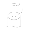
図2に示されるように、本発明の好ましい実施態様にかかる有孔管材1は、空気を送り出すための複数のスリット2aが形成されたスリット部2と、スリット部2よりも有孔管材1の先端部に近い下方位置に形成され、有孔管材1内に土砂が浸入した場合に、浸入した土砂を堆積させ、複数のスリット2aの閉塞を防止する土砂堆積部3を備えている。
As shown in FIG. 2, the perforated
有孔管材1には、スリット部2を閉塞して、複数のスリット2aから土砂が浸入することを防ぐための閉塞部材4が挿入可能で、図3に示されるように、閉塞部材4は中空で、閉塞部材4の内部には、パイプ5が挿入されて固定されている。
The
閉塞部材4の材料は特に限定されるものではないが、たとえば、金属でパイプ5を接する表面に、Oリング(図示せず)などのシール部材が装着されたものや、ゴム、コルク、ウレタンなどが用いられる。
The material of the closing
パイプ3の表面にはマーカー(図2および図3には図示されていない。)が付されている。
A marker (not shown in FIGS. 2 and 3) is attached to the surface of the
このように構成された有孔管材1を用いて、所定量の空気を地盤に注入する場合には、有孔管材1は、以下のようにして、地盤に打ち込まれる。
When a predetermined amount of air is injected into the ground using the
図4は、本発明の好ましい実施態様にかかる有孔管材1を地盤に打ち込んで、所定量の空気を地盤に注入するステップを示す略縦断面図である。
FIG. 4 is a schematic longitudinal sectional view showing a step of injecting a predetermined amount of air into the ground by driving the
図4において、参照符号6で示すのは、パイプ5の表面に付されたマーカーである。
In FIG. 4, reference numeral 6 indicates a marker attached to the surface of the
まず、図4(a)に示されるように、閉塞部材4がスリット部2の複数のスリット2aを閉塞した状態で、有孔管材1が地盤内の所定の位置まで貫入される。
First, as shown in FIG. 4A, the
その後、スリット部2の内容積と土砂堆積部3の内容積の和の2倍ないし3倍の水が、図4(b)に示されるように、パイプ5内に送り込まれ、閉塞部材4の下方の土砂堆積部3内に注入される。この状態では、パイプ5のマーカー6の高さ位置は、有孔管材1の開口端部の高さ位置と一致している。
Thereafter, water twice or three times the sum of the inner volume of the
次いで、図4(c)に示されるように、パイプ5内に加圧空気が注入され、土砂堆積部3内の水圧が上昇される。その結果、閉塞部材4が水圧で、スリット部2の上方に押し上げられ、スリット部2の複数のスリット2aの一部が開放され、複数のスリット2aを通って水が地盤内に流出する。この状態では、パイプ5のマーカー6は、次第に、有孔管材1の開口端部から離れ、上方に移動する。
Next, as shown in FIG. 4 (c), pressurized air is injected into the
ここに、閉塞部材4は水圧によって押し上げられているから、スリット部2内の水圧および土砂堆積部3内の水圧も高く、したがって、複数のスリット2aから土砂が浸入することを効果的に防止することが可能になり、万が一、複数のスリット2aから土砂が浸入した場合には、スリット部2内に充満している水が土砂を洗い出して、スリット2aが目詰まりを起こすことを効果的に防止することができる。
Here, since the closing
次いで、図4(d)に示されるように、閉塞部材4が上方に押し上げられて、複数のスリット2aが完全に開放され、水が複数のスリット2aを通って、地盤内に流出するようになる。その結果、パイプ3内の空気圧力が上がらなくなり、パイプ5のマーカー6の位置が鉛直方向に一定の高さ位置に保持される。
Next, as shown in FIG. 4D, the closing
複数のスリット2aが完全に開放されて、有孔管材1内のすべての水が地盤内に流出すると、図4(e)に示されるように、空気が複数のスリット2aから地盤内に流出するようになる。
When the plurality of
さらに、パイプ5に付されたマーカー6の高さ位置が有孔管材1の開口端部の高さ位置と一致するまで、パイプ5が押し下げられ、閉塞部材4が下降して、複数のスリット2aを介して、有孔管材1内の空気を地盤内に注入する。
Further, the
こうして、図4(f)に示されるように、パイプ5が押し下げられ、マーカー6が下降して、その高さ位置が有孔管材1の開口端部の高さ位置と一致すると、閉塞部材4がスリット部2内の初期位置に戻り、スリット部2の多数のスリット2aは閉塞部材4によって閉塞される。
Thus, as shown in FIG. 4 (f), when the
本実施態様によれば、閉塞部材4がスリット部2の複数のスリット2aを閉塞した状態で、有孔管材1が地盤内の所定の位置まで貫入された後に、スリット部2の内容積と土砂堆積部3の内容積の和の2倍ないし3倍の水が閉塞部材4の下方の土砂堆積部3内に注入され、次いで、土砂堆積部3内に加圧空気が注入され、その結果、閉塞部材4が水圧で、スリット部2の上方に押し上げられて、一部のスリット2aが開放されるが、開放されたスリット2aからは加圧された水が地盤内に流出しているから、開放されたスリット2aから土砂が有孔管材1内に流入することを効果的に防止することができ、有孔管材1内から、水が地盤内に流出すると、その体積に見合った空気がスリット部2と土砂堆積部3内の空間に注入されるから、閉塞部材4が上昇して、スリット部2のすべてのスリット2aが開放されても、スリット2aからは加圧空気が地盤に注入され、この状態を保ちつつ、パイプ5が有孔管材1内に押し込まれて、スリット部2のすべてのスリット2aが閉塞部材4によって閉塞されるから、スリット2aから土砂が有孔管材1内に流入することを効果的に防止することが可能になる。
According to this embodiment, after the
さらに、本実施態様によれば、閉塞部材4の下面に水圧を作用させることによって、閉塞部材4が押し上げられ、スリット2aが開放されるように構成されているため、ホースから水を供給して、有孔管材1内を洗浄する場合に比して、時間も手間もかからないで、有孔管材1内を効率的に洗浄し、スリット2aに目詰まりを解消することができる。
Further, according to the present embodiment, the water pressure is applied to the lower surface of the closing
また、本実施態様によれば、スリット部2および土砂堆積部3に加圧した水を供給しているから、開放されたスリット2から土砂の侵入を防ぐことができるだけでなく、同時に、有孔管材1のスリット部2および土砂堆積部3を洗浄することもでき、目詰まりをしていたスリット2aの目詰まりを解消することもできる。
Moreover, according to this embodiment, since the pressurized water is supplied to the
図5は、本発明の別の好ましい実施態様にかかる有孔管材1を地盤に打ち込んで、所定量の空気を地盤に注入するステップを示す略縦断面図である。
FIG. 5 is a schematic longitudinal sectional view showing a step of driving a
まず、図5(a)に示されるように、閉塞部材4がスリット部2の複数のスリット2aを閉塞した状態で、有孔管材1が地盤内の所定の位置まで貫入される。
First, as shown in FIG. 5A, the
次いで、図5(b)に示されるように、加圧空気がパイプ5内に注入され、閉塞部材4の下方に位置する土砂堆積部3内に加圧空気が注入される。この状態では、パイプ5のマーカー6の高さ位置は、有孔管材1の開口端部の高さ位置と一致している。
Next, as shown in FIG. 5B, the pressurized air is injected into the
次いで、図5(c)に示されるように、パイプ5内に加圧空気が注入され、土砂堆積部3内の空気圧が上昇するため、閉塞部材4が空気圧で、スリット部2の上方に押し上げられ、スリット部2の複数のスリット2aの一部が開放される。その結果、空気が複数のスリット2aを通って、地盤内に流出する。この状態では、パイプ5のマーカー6は、次第に、有孔管材1の開口端部から離れ、上方に移動する。
Next, as shown in FIG. 5 (c), pressurized air is injected into the
ここに、閉塞部材4は空気圧によって押し上げられているから、スリット部2内の空気圧も高く、したがって、複数のスリット2aから土砂が浸入することを効果的に防止することが可能になる。
Here, since the closing
さらに、図5(d)に示されるように、閉塞部材4が上方に押し上げられて、複数のスリット2aが完全に開放され、空気が複数のスリット2aを通って、地盤内に流出するようになる。その結果、パイプ3内の空気圧力が上がらなくなり、パイプ5のマーカー6の位置が鉛直方向に一定の高さ位置に保持される。
Further, as shown in FIG. 5 (d), the closing
さらに、パイプ5を押し込んで、閉塞部材4を下降させ、複数のスリット2aを介して、有孔管材1内の空気を地盤内に注入する。
Furthermore, the
こうして、図5(e)に示されるように、パイプ5が押し下げられ、マーカー6が下降して、その高さ位置が有孔管材1の開口端部の高さ位置と一致すると、閉塞部材4がスリット部2内の初期位置に戻り、スリット部2の複数のスリット2aは閉塞部材4によって閉塞される。
Thus, as shown in FIG. 5 (e), when the
本実施態様によれば、閉塞部材4がスリット部2の複数のスリット2aを閉塞した状態で、有孔管材1が地盤内の所定の位置まで貫入された後に、パイプ5から加圧空気が閉塞部材4の下方の土砂堆積部3内に注入されるから、閉塞部材4が空気圧で、スリット部2の上方に押し上げられて、一部のスリット2aが開放されるが、開放されたスリット2aからは加圧された空気が地盤内に流出しているから、開放されたスリット2aから土砂が有孔管材1内に流入することを効果的に防止することができ、有孔管材1内から空気が地盤内に流出すると、その体積に見合った空気がスリット部2と土砂堆積部3内の空間に注入されるから、閉塞部材4が上昇して、スリット部2のすべてのスリット2aが開放されても、スリット2aからは加圧空気が地盤に注入され、この状態を保ちつつ、パイプ5が有孔管材1内に押し込まれて、スリット部2のすべてのスリット2aが閉塞部材4によって閉塞されるから、スリット2aから土砂が有孔管材1内に流入することを効果的に防止することが可能になる。
According to this embodiment, after the
さらに、本実施態様によれば、図4に示された実施態様に比し、有孔管材1内に加圧された水を供給するというステップが省略されるから、コストを削減することができる。
Furthermore, according to this embodiment, compared with the embodiment shown in FIG. 4, the step of supplying pressurized water into the
有孔管材1内に加圧された水を供給するか、加圧空気を供給するかの選択は、地盤条件にしたがって行い、地盤が非常に緩く、土砂が侵入しやすい地盤に対しては、加圧された水を供給するようにし、それ以外の地盤に対しては、加圧空気を供給するように、使い分けることが好ましい。
The selection of whether to supply pressurized water or pressurized air into the
図6は、本発明の他の好ましい実施態様にかかる有孔管材1を地盤に打ち込んで、所定量の空気を地盤に注入するステップを示す略縦断面図である。
FIG. 6 is a schematic longitudinal sectional view showing a step of driving a
本実施態様においては、有孔管材1の閉塞部材4にはパイプ5は取り付けられておらず、閉塞部材4は、パイプ5と連結される部分にカップリング部材7を備えている。
In this embodiment, the
図7は、カップリング部材7とパイプ5との連結部の詳細を示す略縦断面図である。
FIG. 7 is a schematic longitudinal sectional view showing details of a connecting portion between the
図7に示されるように、カップリング部材7は閉塞部材4に取り付けられたオス・カップリング7aによって構成され、一方、パイプ5の下端部にはメス・カップリング5aが形成され、互いに連結されている。オス・カップリング7aには止水用のOリング7bが設けられているが、Oリング7bに代えて、他のシール材を用いることができる。
As shown in FIG. 7, the
まず、図6(a)に示されるように、閉塞部材4がスリット部2の複数のスリット2aを閉塞した状態で、有孔管材1が地盤内の所定の位置まで貫入される。
First, as shown in FIG. 6A, the
次いで、図6(b)に示されるように、パイプ5が有孔管材1内に挿入され、パイプ5が閉塞部材4のカップリング部材7と連結される。この状態では、パイプ5に付されたマーカー6の高さ位置は、有孔管材1の開口端部の高さ位置と一致している。
Next, as shown in FIG. 6B, the
パイプ5が閉塞部材4のカップリング部材7と連結された後、スリット部2の内容積と土砂堆積部3の内容積の和の2倍ないし3倍の水が、パイプ5内に送り込まれて、閉塞部材4の下方の土砂堆積部3内に注入され、さらに、パイプ5内に加圧空気が送られる。
After the
その結果、図6(c)に示されるように、閉塞部材4が水圧で押し上げられて、スリット部2の複数のスリット2aの一部が開放され、水が一部のスリット2aを介して地盤内に流出する。この状態では、パイプ5のマーカー6は次第に上昇する。
As a result, as shown in FIG. 6C, the closing
さらに、図6(d)に示されるように、閉塞部材4が上方に押し上げられて、すべてのスリット2aが完全に開放され、水がスリット2aを通って、地盤内に流出する。その結果、パイプ3内の空気圧力が上がらなくなり、パイプ5のマーカー6の位置が鉛直方向に一定の高さ位置に保持される。
Further, as shown in FIG. 6 (d), the closing
すべてのスリット2aが完全に開放されて、有孔管材1内のすべての水が地盤内に流出すると、図6(e)に示されるように、空気が複数のスリット2aから地盤内に流出するようになる。
When all the
さらに、パイプ5に付されたマーカー6の高さ位置が有孔管材1の開口端部の高さ位置と一致するまで、パイプ5が押し下げられて、閉塞部材4が下降され、その結果、複数のスリット2aを介して、有孔管材1内の空気が地盤内に注入される。
Furthermore, the
こうして、図6(f)に示されるように、スリット部2の多数のスリット2aは閉塞部材4によって閉塞され、閉塞部材4がスリット部2内の初期位置に復帰する。
Thus, as shown in FIG. 6 (f), the
閉塞部材4がスリット部2内の初期位置に戻ると、閉塞部材4に設けられたカップリング部材7とパイプ5との連結が解除され、図6(g)に示されるように、パイプ5が取り去られる。
When the closing
本実施態様においては、図4に示された実施態様により得られる効果に加えて、パイプ5はカップリング部材7によって、閉塞部材4に連結され、閉塞部材4とは着脱自在であるので、パイプ5を再利用することができ、したがって、コストを削減することが可能になる。
In this embodiment, in addition to the effects obtained by the embodiment shown in FIG. 4, the
本発明は、以上の実施態様に限定されることなく、特許請求の範囲に記載された発明の範囲内で種々の変更が可能であり、それらも本発明の範囲内に包含されるものであることはいうまでもない。 The present invention is not limited to the above-described embodiments, and various modifications are possible within the scope of the invention described in the claims, and these are also included in the scope of the present invention. Needless to say.
たとえば、図6に示された実施態様においては、パイプ5内に加圧空気を送り込むように構成されているが、パイプ5をカップリング部材7から取り外して、有孔管材1に直接、加圧空気を送り込むようにすることもできる。
For example, in the embodiment shown in FIG. 6, it is configured to send pressurized air into the
1 有孔管材
2 スリット部
2a スリット
3 土砂堆積部
4 閉塞部材
5 パイプ
5a メス・カップリング
6 マーカー
7 カップリング部材
7a オス・カップリング
7b Oリング
11 有孔管材
12 スリット部
12a スリット
13 中空のパイプ
14 土砂
DESCRIPTION OF
Claims (6)
前記スリット部の内面と摺動可能で、前記複数のスリットをすべて閉塞するように配置された中空な閉塞部材と、
前記中空な閉塞部材の中空部を通って、加圧された水または加圧空気を前記中空な閉塞部材の下方の前記土砂堆積部に注入可能なパイプ部材を備えており、
前記中空な閉塞部材は、前記パイプ部材を介して前記土砂堆積部に注入された水または空気の圧力によって上方に移動可能であり、かつ、前記パイプ部材を押し下げることにより下方に移動可能であることを特徴とする有孔管材。 It has a slit part where a plurality of slits are formed and a sediment deposit part where sediment can be deposited,
A hollow closing member that is slidable with the inner surface of the slit portion and is arranged to close all the plurality of slits;
A pipe member capable of injecting pressurized water or pressurized air into the sediment deposit part below the hollow closing member through the hollow portion of the hollow closing member ;
The hollow blocking member can be moved upward by the pressure of water or air injected into the sediment accumulation part through the pipe member, and can be moved downward by pushing down the pipe member. Perforated pipe material characterized by
パイプ部材を用いて、前記閉塞部材の中空部を通って、加圧された水または加圧空気を前記閉塞部材の下方の土砂堆積部に注入して、前記閉塞部材を押し上げ、
前記複数のスリットを開放させて、前記複数のスリットから加圧された水または加圧空気を地盤内に流出させ、
前記加圧された水または加圧空気によって、前記中空な閉塞部材が押し上げて、前記複数のスリットを開放し、
前記パイプ部材を介して、注入された加圧された水または加圧空気が前記複数のスリットから地盤内に流出した後に、
前記パイプ部材内に加圧空気を供給することによって、加圧空気を前記複数のスリットから地盤内に流出させつつ、
前記閉塞部材を前記スリット部の複数のスリットを閉鎖する位置に復帰させることを特徴とする有孔管材の打ち込み方法。 It has a slit part in which a plurality of slits are formed, and penetrates a perforated pipe material in which a hollow blocking member is arranged at a position for closing the plurality of slits into the ground,
Using a pipe member, through the hollow part of the closing member, injected pressurized water or pressurized air into the sediment deposit part below the closing member, and pushes up the closing member,
Opening the plurality of slits, causing water or pressurized air pressurized from the plurality of slits to flow into the ground,
With the pressurized water or pressurized air, the hollow closing member is pushed up to open the plurality of slits,
After the injected pressurized water or pressurized air flows out from the plurality of slits into the ground through the pipe member,
By supplying pressurized air into the pipe member, while allowing the pressurized air to flow into the ground from the plurality of slits,
A method for driving a perforated pipe material, wherein the closing member is returned to a position where a plurality of slits of the slit portion are closed.
Priority Applications (1)
| Application Number | Priority Date | Filing Date | Title |
|---|---|---|---|
| JP2014004890A JP6300532B2 (en) | 2014-01-15 | 2014-01-15 | Perforated pipe material and method for driving the same |
Applications Claiming Priority (1)
| Application Number | Priority Date | Filing Date | Title |
|---|---|---|---|
| JP2014004890A JP6300532B2 (en) | 2014-01-15 | 2014-01-15 | Perforated pipe material and method for driving the same |
Publications (2)
| Publication Number | Publication Date |
|---|---|
| JP2015132127A JP2015132127A (en) | 2015-07-23 |
| JP6300532B2 true JP6300532B2 (en) | 2018-03-28 |
Family
ID=53899551
Family Applications (1)
| Application Number | Title | Priority Date | Filing Date |
|---|---|---|---|
| JP2014004890A Active JP6300532B2 (en) | 2014-01-15 | 2014-01-15 | Perforated pipe material and method for driving the same |
Country Status (1)
| Country | Link |
|---|---|
| JP (1) | JP6300532B2 (en) |
Families Citing this family (1)
| Publication number | Priority date | Publication date | Assignee | Title |
|---|---|---|---|---|
| JP6767133B2 (en) * | 2016-02-29 | 2020-10-14 | 大成建設株式会社 | Pipe driving method and pipe material driving unit |
Family Cites Families (3)
| Publication number | Priority date | Publication date | Assignee | Title |
|---|---|---|---|---|
| JPH08269938A (en) * | 1995-04-03 | 1996-10-15 | Toda Constr Co Ltd | Strainer with variable slit position |
| JP2006291467A (en) * | 2005-04-06 | 2006-10-26 | Makoto Oishi | Method for clearing clogging in existing well |
| US20100300986A1 (en) * | 2009-05-27 | 2010-12-02 | Harout Ohanesian | Well filter |
-
2014
- 2014-01-15 JP JP2014004890A patent/JP6300532B2/en active Active
Also Published As
| Publication number | Publication date |
|---|---|
| JP2015132127A (en) | 2015-07-23 |
Similar Documents
| Publication | Publication Date | Title |
|---|---|---|
| US9371716B2 (en) | Self-extendable hydraulic wellbore cleaning tool | |
| JP5543421B2 (en) | How to build a well | |
| JP6300532B2 (en) | Perforated pipe material and method for driving the same | |
| JP4876020B2 (en) | Well construction method and perforated pipe material | |
| JP5063228B2 (en) | Cleaning method and apparatus for deep well pipe | |
| JP5572469B2 (en) | Hardener injection mechanism | |
| JP5693520B2 (en) | Method for discharging earth and sand inside the joint of steel pipe sheet piles | |
| JP6329385B2 (en) | Implantable injection tube | |
| KR101161158B1 (en) | Cleaning device for drilling rod of drilling machine | |
| JP5695898B2 (en) | A ground improvement device that improves the ground by injecting high-pressure fluid from the tip of multiple pipes. | |
| KR101372236B1 (en) | Hose connecting module for filling tube and dredge soils injection device with the same | |
| JP6313113B2 (en) | Method and apparatus for sucking up sediment from well bottom | |
| JP5391256B2 (en) | How to build a well | |
| US10018016B2 (en) | Wireline fluid blasting tool and method | |
| CA2908009C (en) | Enhanced erosion resistant wire shapes | |
| JP5205312B2 (en) | Water flow management system and water-sealed underground tank | |
| JP2012136842A (en) | Ground improvement device improving ground by injecting high pressure fluid through multiple pipe tip | |
| JP2002242240A (en) | Pumping method of well and pumping pump of well | |
| RU5422U1 (en) | DEVICE FOR PREVENTING SANDING WELLS | |
| CN202611644U (en) | Water injection well completion string | |
| JP5702238B2 (en) | Drainage pipe and ground improvement method | |
| CN110359893B (en) | Mine jet fracturing device and operation method | |
| JP6104961B2 (en) | Mobile driving machine | |
| EP3494282B1 (en) | Coiled tubing arrangement for wellbore unloading | |
| JPS6328185B2 (en) |
Legal Events
| Date | Code | Title | Description |
|---|---|---|---|
| RD02 | Notification of acceptance of power of attorney |
Free format text: JAPANESE INTERMEDIATE CODE: A7422 Effective date: 20161003 |
|
| A621 | Written request for application examination |
Free format text: JAPANESE INTERMEDIATE CODE: A621 Effective date: 20161108 |
|
| A977 | Report on retrieval |
Free format text: JAPANESE INTERMEDIATE CODE: A971007 Effective date: 20171005 |
|
| A131 | Notification of reasons for refusal |
Free format text: JAPANESE INTERMEDIATE CODE: A131 Effective date: 20171017 |
|
| A521 | Request for written amendment filed |
Free format text: JAPANESE INTERMEDIATE CODE: A523 Effective date: 20171116 |
|
| TRDD | Decision of grant or rejection written | ||
| A01 | Written decision to grant a patent or to grant a registration (utility model) |
Free format text: JAPANESE INTERMEDIATE CODE: A01 Effective date: 20180213 |
|
| A61 | First payment of annual fees (during grant procedure) |
Free format text: JAPANESE INTERMEDIATE CODE: A61 Effective date: 20180227 |
|
| R150 | Certificate of patent or registration of utility model |
Ref document number: 6300532 Country of ref document: JP Free format text: JAPANESE INTERMEDIATE CODE: R150 |
|
| R250 | Receipt of annual fees |
Free format text: JAPANESE INTERMEDIATE CODE: R250 |
|
| R250 | Receipt of annual fees |
Free format text: JAPANESE INTERMEDIATE CODE: R250 |
|
| R250 | Receipt of annual fees |
Free format text: JAPANESE INTERMEDIATE CODE: R250 |