JP6347324B2 - Pile construction jig and rotation pile construction method - Google Patents
Pile construction jig and rotation pile construction method Download PDFInfo
- Publication number
- JP6347324B2 JP6347324B2 JP2014119067A JP2014119067A JP6347324B2 JP 6347324 B2 JP6347324 B2 JP 6347324B2 JP 2014119067 A JP2014119067 A JP 2014119067A JP 2014119067 A JP2014119067 A JP 2014119067A JP 6347324 B2 JP6347324 B2 JP 6347324B2
- Authority
- JP
- Japan
- Prior art keywords
- shaft portion
- pile
- pile construction
- exterior body
- divided
- Prior art date
- Legal status (The legal status is an assumption and is not a legal conclusion. Google has not performed a legal analysis and makes no representation as to the accuracy of the status listed.)
- Active
Links
Images
Landscapes
- Placing Or Removing Of Piles Or Sheet Piles, Or Accessories Thereof (AREA)
Description
本発明は、地盤に回転杭を回転貫入する際に用いる杭施工治具、及び、この杭施工治具によって施工される回転杭に関する。 The present invention relates to a pile construction jig used when a rotary pile is rotated and penetrated into the ground, and a rotary pile constructed by the pile construction jig.
従来、建築物、道路、鉄道高架橋、橋台、鉄塔等の土木構造物等の上部構造を支持するため、また、地滑りの防止のために地盤に回転貫入されて設置される回転杭(鋼管杭)が知られている。 Conventionally, rotating piles (steel pipe piles) installed to support the upper structure of civil engineering structures such as buildings, roads, railway viaducts, abutments, and steel towers, and to prevent landslides. It has been known.
このような回転杭には、例えば特許文献1に示すように、内周面や外周面に径方向外側に突出するコマと呼ばれる突起物(係合部)が設けられている。そして、施工装置の回転力をこの突起物によって受けることで、施工装置から回転杭に回転力を伝達可能となっている。
For example, as shown in
しかしながら、このような突起物は、素管の鋼管に溶接によって接合して設けられることが一般的である。このため、突起物を接合する手間が必要となり、コストアップにつながっている。さらに、突起物を溶接して接合する場合には、鋼管にある程度の肉厚が必要となり、材料費や重量が増大してしまうといった問題がある。このため、このような突起物を設けずに回転杭を回転貫入できるようにする手法が求められている。 However, such protrusions are generally provided by welding to a steel pipe of a raw pipe. For this reason, the effort which joins a protrusion is needed and it has led to the cost increase. Furthermore, when joining protrusions by welding, there is a problem that the steel pipe needs to have a certain thickness and the material cost and weight increase. For this reason, the method of enabling rotation penetration of a rotary pile without providing such a protrusion is calculated | required.
本発明は、上述した事情に鑑みてなされたものであって、簡易な構造で、回転杭に容易に取り付けることができ、回転杭を回転貫入することが可能な杭施工治具、及び、この杭施工治具によって施工される回転杭を提供する。 The present invention has been made in view of the above-described circumstances, and has a simple structure, can be easily attached to a rotating pile, and a pile construction jig capable of rotating through the rotating pile, and this A rotating pile constructed by a pile construction jig is provided.
本発明は、上記課題を解決するために、以下の手段を採用する。
即ち、本発明の一の態様に係る杭施工治具は、管状をなす軸部を有する回転杭を、地盤に回転貫入する杭施工治具であって、前記軸部の周方向に複数に分割された外側分割片を有して全体で管状の部材を形成するとともに、前記軸部を外側から覆って該軸部に接触可能な外装体と、前記外側分割片同士を互いに近接する方向に締め付ける締付力を付与する締結部と、前記外側分割片の外面に該外側分割片と一体に設けられ、前記軸部の周方向の一部で該軸部の径方向外側に向けて突出し、前記回転杭を回転貫入させる施工装置からの回転力を受けるコマ部と、前記外装体の内側に位置するように前記軸部の内側に挿入されて、該内側から該軸部の径方向外側に向かって該軸部に押圧力を付与する内装体と、を備えることを特徴とする。
The present invention employs the following means in order to solve the above problems.
That is, the pile construction jig according to an aspect of the present invention is a pile construction jig for rotating and penetrating a rotary pile having a tubular shaft portion into the ground, and is divided into a plurality of pieces in the circumferential direction of the shaft portion. A tubular member is formed as a whole with the outer divided pieces formed, and the outer cover that covers the shaft portion from the outside and can come into contact with the shaft portion and the outer divided pieces are tightened in a direction close to each other. A fastening portion for applying a tightening force; and provided on the outer surface of the outer divided piece integrally with the outer divided piece, projecting toward a radially outer side of the shaft portion at a part in a circumferential direction of the shaft portion, A top part that receives a rotational force from a construction device that rotates and penetrates the rotary pile, and a shaft part that is inserted inside the shaft part so as to be located inside the exterior body, from the inner side toward a radially outer side of the shaft part. And an interior body for applying a pressing force to the shaft portion .
このような杭施工治具によれば、複数に分割された外装体を締結部によって締め付けることで外装体を軸部の外周面に密着させることができる。従って、軸部と外装体との間に摩擦力を発生させることができ、施工装置からの回転力が外装体に付与された際に、この摩擦力によって軸部と施工装置との間の相対回転が規制され、施工装置からの回転力を伝達可能となる。また、外装体は分割された外側分割片により構成されているので、外装体が一体となっている場合の外装体全体に比べて、各々の外側分割片は小さく、軽く、外装体の運搬や軸部への取り付けが容易となる。さらに、単純な分割構造の外装体を用いていることで、構造がシンプルであり、製造コストを抑えることができる。 According to such a pile construction jig, the exterior body can be brought into close contact with the outer peripheral surface of the shaft portion by fastening the exterior body divided into a plurality by the fastening portion. Accordingly, a frictional force can be generated between the shaft part and the exterior body, and when the rotational force from the construction apparatus is applied to the exterior body, the frictional force causes a relative force between the shaft part and the construction apparatus. The rotation is restricted, and the rotational force from the construction device can be transmitted. Further, since the exterior body is composed of divided outer divided pieces, each outer divided piece is smaller and lighter than the entire exterior body when the exterior body is integrated, Attachment to the shaft is easy. Furthermore, the structure is simple and the manufacturing cost can be suppressed by using a simple divided exterior body.
このような内装体を設けることで軸部を内側から押圧することが可能となり、軸部を外装体に押し付けることで、これら軸部と外装体との密着性を向上できる。よって、軸部と外装体との間にさらに大きな摩擦力を発生させることができ、施工装置からの回転力をより効果的に軸部に伝達可能となる。 By providing such an interior body, it is possible to press the shaft portion from the inside, and by pressing the shaft portion against the exterior body, the adhesion between the shaft portion and the exterior body can be improved. Therefore, a larger frictional force can be generated between the shaft portion and the exterior body, and the rotational force from the construction apparatus can be transmitted to the shaft portion more effectively.
また、前記内装体は、前記押圧力を調整可能となっていてもよい。 The interior body may be capable of adjusting the pressing force.
このように押圧力を調整できることで、軸部の寸法精度等の影響を受けることなく、効果的に軸部を外装体に密着させることができ、軸部と外装体との間に摩擦力を発生させることができる。 By adjusting the pressing force in this way, the shaft portion can be effectively brought into close contact with the exterior body without being affected by the dimensional accuracy of the shaft portion, and a frictional force can be generated between the shaft portion and the exterior body. Can be generated.
さらに、前記内装体は、前記締結部によって付与される前記締付力の作用方向とは、前記径方向に異なる方向に前記押圧力が作用するように、該押圧力を付与してもよい。 Further, the inner body may apply the pressing force so that the pressing force acts in a direction different from the radial direction of the tightening force applied by the fastening portion.
仮に、押圧力の方向と締付力の方向とが一致している場合には、その一致している部分のみに力が集中してしまうため、軸部と外装体と密着性を十分に得ることができない可能性があるが、押圧力の方向と締付力の方向とが異なることで、より効果的に軸部と外装体とを密着させ、摩擦力を発生させることができる。 If the direction of the pressing force and the direction of the tightening force coincide with each other, the force concentrates only on the coincident portion, so that sufficient adhesion between the shaft portion and the exterior body is obtained. However, since the direction of the pressing force and the direction of the tightening force are different, the shaft portion and the exterior body can be more effectively brought into close contact with each other to generate a frictional force.
また、前記内装体は、前記軸部の周方向に複数に分割された内側分割片を有して全体で管状の部材を形成するとともに前記軸部の内周面に接触可能な接触部と、前記内側分割片同士を前記径方向外側に向かって互いに離間する方向に押圧する押圧力を付与する押圧部と、を備えていてもよい。 Further, the inner body has an inner divided piece divided into a plurality in the circumferential direction of the shaft portion to form a tubular member as a whole and a contact portion that can contact the inner peripheral surface of the shaft portion; And a pressing portion that applies a pressing force that presses the inner divided pieces in a direction away from each other toward the radially outer side.
このように、内装体として接触部を設けることで、軸部の内周面の周方向のより広い範囲にわたって押圧力を付与することが可能となる。また、内装体における接触部は分割された内側分割片により構成されているので、接触部が一体となっている場合の接触部全体に比べて、各々の内側分割片は小さく、軽くなり、内装体の運搬や軸部への取り付けが容易となる。さらに、単純な分割構造の内装体を用いていることで、構造がシンプルであり、製造コストを抑えることができる。 Thus, by providing the contact portion as the interior body, it is possible to apply a pressing force over a wider range in the circumferential direction of the inner peripheral surface of the shaft portion. Moreover, since the contact part in an interior body is comprised by the divided | segmented inner division | segmentation piece, compared with the whole contact part when the contact part is united, each inner division | segmentation piece becomes small and light, The body can be easily transported and attached to the shaft. Furthermore, the structure is simple and the manufacturing cost can be reduced by using an interior body with a simple divided structure.
さらに、本発明の一の態様に係る回転杭の施工方法は、上記の杭施工治具を用いて地盤に回転杭を回転貫入する方法であって、前記内装体によって前記軸部を内側から押圧しながら前記外装体を前記締結部によって締め付けた状態で、前記施工装置から前記コマ部に回転力を付与することを特徴とする。 Furthermore, the construction method of the rotary pile according to one aspect of the present invention is a method of rotationally penetrating the rotary pile into the ground using the above pile construction jig, and pressing the shaft portion from the inside by the interior body. While the exterior body is tightened by the fastening portion, a rotational force is applied from the construction device to the top portion .
このような回転杭によれば、杭施工治具を用いることで、軸部と外装体との間に摩擦力を発生させ、この摩擦力によって施工装置からの回転力が伝達される。そして、軸部へ容易に取り付けられるとともに、製造コストを抑えながら回転貫入が可能となる。 According to such a rotary pile, by using a pile construction jig, a frictional force is generated between the shaft portion and the exterior body, and the rotational force from the construction device is transmitted by this frictional force. And while being easily attached to an axial part, rotation penetration is attained, suppressing manufacturing cost.
請求項1の杭施工治具によると、外装体を設けることで、簡易な構造で、回転杭に容易に取り付けることができ、回転杭を回転貫入することが可能となる。
According to the pile construction jig of
また、請求項1の杭施工治具によると、内装体を設けることで、効率よく回転杭を回転貫入することができる。
Moreover, according to the pile construction jig of
また、請求項2の杭施工治具によると、さらに効率よく、回転杭を回転貫入することができる。
Moreover, according to the pile construction jig of
また、請求項3の杭施工治具によると、さらに効率よく、回転杭を回転貫入することができる。
Moreover, according to the pile construction jig of
また、請求項4の杭施工治具によると、さらに効率よく、回転杭を回転貫入することができる。 Moreover, according to the pile construction jig of claim 4 , it is possible to rotate the rotary pile more efficiently.
さらに、請求項5の回転杭の施工方法によると、簡易な構造であって、容易に取り付けることができる杭施工治具を用いることで、容易に回転貫入される。
Furthermore, according to the construction method of the rotary pile of
以下、本実施形態の杭施工治具1について説明する。
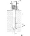
杭施工治具1は、回転杭100に取り付けられて回転杭100を地盤Gに回転貫入する治具である。
ここで、本実施形態で地盤Gに回転貫入される回転杭100は、鋼管よりなる軸部101と、軸部101の外周面101aに設けられた羽根部102とを有している。
Hereinafter, the
The
Here, the
軸部101は、軸線Oに沿って延在する例えば円形鋼管の素管であって、構造物の設計強度等に応じて外径、及び肉厚等の寸法は適宜変更される。
The
羽根部102は、軸部101の外周面101aから径方向外側に突出し、軸部101が地盤Gに貫入される側となる先端から基端側に向かって軸線Oの方向に捩れるように形成された螺旋羽根である。本実施形態ではこの羽根部102は軸部101の先端から、軸部101の周方向に一周分だけ形成されている。
なお、この羽根部102は軸部101の軸線Oの方向の全域にわたって形成されていてもよい。また、軸線Oの方向に不連続となるように間隔をあけて形成されていてもよい。
The
The
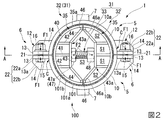
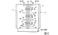
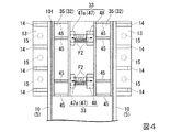
図2から図4に示すように、杭施工治具1は、軸部101の基端に外側から取り付けられる外装体5と、外装体5に設けられた締結部6及びコマ部7と、軸部101の基端で内側に挿入された内装体31とを備えている。
As shown in FIGS. 2 to 4, the
外装体5は、軸部101の周方向に複数(本実施形態では二つ)に分割された外側分割片10を有し、これら複数の外側分割片10全体で管状部材を形成するようになっている。
さらに、これら外側分割片10の内面10aは、軸部101に取り付けられた状態で軸部101の外周面101aに接触し、外装体5と軸部101とが同軸上に配置される。
The
Furthermore, the
ここで、外側分割片10の内面10aが軸部101の外周面101aに接触し、かつ、外側分割片10に外力が加えられない状態では、外側分割片10同士は互いに周方向に離間しており、外側分割片10同士の間に隙間が形成されている。
Here, in a state where the
締結部6は、各々の外側分割片10から、外装体5の径方向外側に向かって突出する締結板部12と、軸部101の周方向に隣接する外側分割片10における締結板部12同士を締結するボルト15及びナット16とを有している。
The
締結板部12は、各々の外側分割片10の周方向の両端部で、軸線Oの方向の全域にわたって径方向外側に突出する板状をなす第一板13と、第一板13と外側分割片10の外面10bとの間に形成されたコーナー部Cに設けられた板状をなす第二板14とを有している。
The
第一板13は、各々の外側分割片10が軸部101に取り付けられた状態で、周方向に隣接する外側分割片10のうちの一方における第一板13と、他方における第一板13とが周方向に対向して配置されるようになっている。
The
また、この第一板13には、外側分割片10の周方向に沿って板厚方向に貫通する貫通孔13aが形成されている。この貫通孔13aは、上記一方の外側分割片10における第一板13と、上記他方の外側分割片10における第一板13とが周方向に対向した状態で、軸線O方向に略同じ高さ位置に配置されるように、各々の第一板13に形成されている。本実施形態では、この貫通孔13aは、軸線Oの方向に互いに離間して等間隔に三つが形成されている。
Further, the
第二板14は、第一板13と交差(本実施形態では直交)するように、外装体5の周方向延びており、いわゆるリブの機能を有するリブ板となっている。さらにこの第二板14は、第一板13における貫通孔13aを軸線Oの方向の両側から挟むように、軸線Oの方向に互いに離間して複数(本実施形態では四つ)が設けられている。
The
そして、第二板14の径方向外側を向く端面22は、第一板13の径方向外側を向く端面21と面一になっている。より詳しくは、本実施形態では、第二板14の端面22は、第一板13の端面21に連続するように、外側分割片10の外面10bの接線方向に延びる面22aと、この面22aに連続して第一板13から離間する方向に向かって、径方向外側から内側に向かって面取りされたように傾斜する面22bとを有して構成されている。
The
ボルト15は、互いに周方向に対向する第一板13における貫通孔13aに挿通される。
ナット16はボルトに螺合することで、周方向に対向する第一板13同士を互いに近接する方向に締め付ける締付力F1を付与する。このような締付力F1によって、外側分割片10同士が互いに近接するように引っ張られる。
The
The
コマ部7は、外側分割片10から径方向外側に突出するように外側分割片10と一体に軸線O方向の全域にわたって設けられている。このコマ部7は、各々の外側分割片10における第一板13同士の間となる周方向の中間位置に一つずつ配されている。従って、本実施形態では、各々の外側分割片10に設けられたコマ部7は、軸線O回りに周方向に180度離間した位置に配されていることになる。
The
図1に示すように、軸部101の基端には、筒状の施工装置200が覆うように設けられ、施工装置200に設けられた突起部201がコマ部7に係合することで、施工装置200からの回転力が軸部101に伝えられる。
As shown in FIG. 1, the base end of the
図2及び図4に示すように、内装体31は、軸部101の内側に挿入されて取り付けられ、軸部101の内周面101bに接触可能な接触部32と、接触部32を軸部101の内周面101bに押し付ける押圧部33とを有している。
As shown in FIG. 2 and FIG. 4, the
接触部32は、軸部101の周方向に複数(本実施形態では二つ)に分割された内側分割片35を有し、これら複数の内側分割片35全体で管状部材を形成するようになっている。さらに、これら内側分割片35は、軸部101に取り付けられた状態で、内側分割片35の外面35aは軸部101の内周面101bに接触し、接触部32と軸部101とが同軸上に配置される。
The
ここで、内側分割片35の外面35aが軸部101の内周面101bに接触し、かつ、内側分割片35に外力が加えられない状態では、内側分割片35同士は互いに周方向に離間しており、内側分割片35同士の間に隙間が形成されている。
Here, in a state where the
そして接触部32の分割位置が、外装体5の分割位置とは異なる位置に配されるように、内側分割片35が軸部101の内側に挿入される。本実施形態では、この分割位置が外装体5と接触部32とで、周方向に90度ズレている。
Then, the inner divided
各々の内側分割片35は、軸線Oの方向から見て三日月状をなしており、内部は中空の骨組構造となっている。
より詳しくはこの内側分割片35は、図2に示すように、軸部101の内周面101bに接触可能に、内周面101bに沿って湾曲する円弧状板40と、円弧状板40における周方向中央の位置から接触部32の径方向内側に向かって、軸線Oとの間の中途位置まで突出するとともに、軸線Oの方向にわたって延びる平板状をなす第一縦仕切板41とを有している。
Each inner divided
More specifically, as shown in FIG. 2, the inner divided
また、内側分割片35は、第一縦仕切板41に平行に円弧状板40から離間する方向に、円弧状板40から突出して設けられた平板状をなす一対の第二縦仕切板42を有している。
さらに、内側分割片35は、これら第一縦仕切板41及び第二縦仕切板42に直交して軸線Oの方向に延び、一対の第二縦仕切板42と円弧状板40との間に空間S1を画成する第三縦仕切板43と、円弧状板40の周方向の端縁部から径方向の内側に向かって突出するとともに、軸線Oの方向に延びる平板状をなす端部板46とを有している。
In addition, the inner divided
Further, the inner divided
また、内側分割片35は、各々の第二縦仕切板42と第三縦仕切板43との接続部分となる角部43aと端部板46の径方向内側の端縁46aとを接続し、第二縦仕切板42、端部板46、及び円弧状板40との間に空間S2を画成する一対の第四縦仕切板44を有している。
Further, the inner divided
さらに、内側分割片35は、図4に示すように、第三縦仕切板43及び第四縦仕切板44と円弧状板40との間にわたって設けられた横仕切板45を有している。この横仕切板45は、内側分割片35における軸線Oの両端側の位置と、これらの間との計四か所に、軸線Oの方向に互いに離間して設けられている。
Further, as shown in FIG. 4, the inner divided
そして、接触部32が軸部101に取り付けられた状態では、一方の内側分割片35における第三縦仕切板43及び第四縦仕切板44と、他方の内側分割片35における第三縦仕切板43及び第四縦仕切板44との間に、空間S3が画成されている。
In the state where the
押圧部33は、内側分割片35同士の間に画成された空間S3内に配されて、一方の内側分割片35の第三縦仕切板43から、他方の内側分割片35の第三縦仕切板43に向かって延びるボルト47を有している。そして、一方の内側分割片35における第三縦仕切板43にボルト47のボルト頭47aが溶接等によって接合されている。
また、押圧部33は、ボルト47に螺合するとともに、他方の内側分割片35における第三縦仕切板43に接触して設けられたナット48を有している。
The
The
そして、これらボルト47及びナット48を有する押圧部33は、軸線Oの方向に互いに離間して一対が設けられている。これら一対の押圧部33は、本実施形態では横仕切板45が設けられた軸線Oの方向の位置に対応する位置に設けられている。
A pair of the
押圧部33は、ナット48をボルト47に対して相対回転させることで、ナット48とボルト頭47aとの離間距離を変更可能となっており、一対の内側分割片35に対して、径方向外側に向かって互いに離間する方向に押圧する押圧力F2を付与可能となっている。
The
そして、この押圧部33によって付与される押圧力F2と、外装体5を締め付ける締結部6による締付力F1とが作用する方向は異なっており、本実施形態では、これらの力が直交する方向に作用するようになっている。
The direction in which the pressing force F2 applied by the
このような杭施工治具1によると、複数に分割された外側分割片10を有する外装体5を締結部6によって締め付けることで、外側分割片10が径方向内側に向かうように力が作用し、外側分割片10が軸部101に押し付けられる。従って、外装体5を軸部101の外周面101aに密着させることができ、軸部101と外装体5との間に摩擦力を発生させることができる。
According to such a
そして、施工装置200の突起部201からコマ部7に軸線O回りの回転力が付与されると、軸部101と外装体5との間の摩擦力によって軸部101と施工装置200との間の相対回転が規制されるため、施工装置200からの回転力を軸部101に伝達可能となる。
When a rotational force around the axis O is applied from the
また、外装体5は、分割された外側分割片10により構成されているので、各々の外側分割片10は、外装体5が一体となっている場合の外装体5全体に比べて、各々の外側分割片10は小さく、軽くなり、運搬や軸部101への取り付けが容易となる。
Moreover, since the
さらに、外装体5には、単純な分割構造を採用していることで、構造がシンプルであり、製造コストを抑えることができる。
Furthermore, since the
さらに、内装体31を設けることで、軸部101を内側から押圧することが可能となり、軸部101を外装体5に向けて押し付けることで、これら軸部101と外装体5との密着性をさらに向上できる。よって、さらに大きな摩擦力を軸部101と外装体5との間に発生させることができ、施工装置200からの回転力をより効果的に伝達可能となる。この結果、さらに効率よく回転杭100を回転貫入することができる。
Furthermore, by providing the
仮に、内装体31の押圧力F2の方向と外装体5の締付力F2の方向とが一致している場合には、その一致している部分のみに力が集中してしまうため、軸部101と外装体5と密着性を十分に得ることができない可能性がある。
しかしながら本実施形態では、押圧力F2の方向と締付力F1の方向とが異なることで、これら押圧力F2と締付力F1とを効果的に作用させることができ、効果的に軸部101と外装体5とを密着させ、摩擦力を発生させることができる。
If the direction of the pressing force F2 of the
However, in this embodiment, since the direction of the pressing force F2 and the direction of the tightening force F1 are different, the pressing force F2 and the tightening force F1 can be effectively applied, and the
さらに、内装体31として接触部32を設けることで、軸部101の内周面101bの周方向のより広い範囲(例えば、周方向の全域)にわたって押圧力F2を付与することが可能となる。
Furthermore, by providing the
また、内装体31の接触部32は分割された内側分割片35により構成されているので、各々の内側分割片35は、内装体31が一体となっている場合の接触部32全体に比べて、各々の内側分割片35は小さく、軽くなり、運搬や軸部101への取り付けが容易となる。さらに、内装体31の接触部32として単純な分割構造を採用していることで、構造がシンプルであり、製造コストを抑えることができる。
Moreover, since the
また、外装体5にはリブ板として第二板14が設けられていることで、第一板13同士を締結部6によって締め付けた際に、第一板13が変形してしまうこと抑制でき、外装体5と軸部101との間に効果的に摩擦力を発生させることができる。
Further, since the
本実施形態の杭施工治具1によると、外装体5を設けて、外装体5と軸部101との間に生じる摩擦力を利用することで、簡易な構造で、回転杭100に容易に取り付けることができ、回転杭100を回転貫入することができる。
According to the
以上、本発明の実施形態について説明したが、本発明は上述の実施形態で示した構成に限定されるものではなく、本発明の趣旨を逸脱しない範囲で変更することができる。
例えば、内装体31は必須構成ではなく、外装体5のみを設けてもよい。
さらに、内装体31の接触部32及び外装体5は、二つ以上に分割された構造であってもよい。
As mentioned above, although embodiment of this invention was described, this invention is not limited to the structure shown by the above-mentioned embodiment, It can change in the range which does not deviate from the meaning of this invention.
For example, the
Furthermore, the
また、外装体5のコマ部7は、各々の外側分割片10に複数個ずつ設けられていてもよいし、設置位置も上述の場合に限定されず、施工装置200の突起部201に対応するように設けられていればよい。
Moreover, the
また、締結部6は、ボルト15、ナット16を有するものに代えて、第一板13同士を挟み込むクランプのようなものを用いてもよい。
The
また、内装体31の接触部32の形状、構造等は上述した骨組構造の場合に限定されず、中実のブロック状をなしていてもよい。
Further, the shape, structure, and the like of the
また、内装体31の押圧部33は、ボルト47、ナット48を有するものに代えて、アクチュエータ等を用いてもよい。
The
また、内装体31として接触部32を設けず、押圧部33のみを用いてもよい。
Further, the
1…杭施工治具
5…外装体
6…締結部
7…コマ部
10…外側分割片
10a…内面
10b…外面
12…締結板部
13…第一板
13a…貫通孔
14…第二板
15…ボルト
16…ナット
21…端面
22…端面
22a、22b…面
31…内装体
32…接触部
33…押圧部
35…内側分割片
35a…外面
40…円弧状板
41…第一縦仕切板
42…第二縦仕切板
43…第三縦仕切板
43a…角部
44…第四縦仕切板
45…横仕切板
46…端部板
46a…端縁
47…ボルト
47a…ボルト頭
48…ナット
100…回転杭
101…軸部
101a…外周面
101b…内周面
102…羽根部
200…施工装置
201…突起部
O…軸線
G…地盤
C…コーナー部
S1…空間
S2…空間
S3…空間
F1…締付力
F2…押圧力
DESCRIPTION OF
Claims (5)
前記軸部の周方向に複数に分割された外側分割片を有して全体で管状の部材を形成するとともに、前記軸部を外側から覆って該軸部に接触可能な外装体と、
前記外側分割片同士を互いに近接する方向に締め付ける締付力を付与する締結部と、
前記外側分割片の外面に該外側分割片と一体に設けられ、前記軸部の周方向の一部で該軸部の径方向外側に向けて突出し、前記回転杭を回転貫入させる施工装置からの回転力を受けるコマ部と、
前記外装体の内側に位置するように前記軸部の内側に挿入されて、該内側から該軸部の径方向外側に向かって該軸部に押圧力を付与する内装体と、
を備えることを特徴とする杭施工治具。 A pile construction jig for rotating and penetrating a rotary pile having a tubular shaft part into the ground,
An exterior body that has an outer divided piece divided into a plurality of portions in the circumferential direction of the shaft portion to form a tubular member as a whole, covers the shaft portion from the outside, and can contact the shaft portion;
A fastening portion for applying a tightening force to fasten the outer divided pieces in a direction close to each other;
From the construction device that is provided integrally with the outer divided piece on the outer surface of the outer divided piece, projects toward the radially outer side of the shaft portion at a part in the circumferential direction of the shaft portion, and rotates the rotary pile. The top part that receives the rotational force,
An interior body that is inserted inside the shaft portion so as to be located inside the exterior body and applies a pressing force to the shaft portion from the inside toward the radially outer side of the shaft portion;
A pile construction jig characterized by comprising:
前記内側分割片同士を前記径方向外側に向かって互いに離間する方向に押圧する押圧力を付与する押圧部と、
を備えることを特徴とする請求項1から3のいずれか一項に記載の杭施工治具。 The inner body has an inner divided piece divided into a plurality in the circumferential direction of the shaft portion to form a tubular member as a whole and a contact portion that can contact the inner peripheral surface of the shaft portion;
A pressing portion for applying a pressing force for pressing the inner divided pieces in a direction away from each other toward the radially outer side;
Pile construction jig according to any one of claims 1 to 3, characterized in that it comprises a.
前記内装体によって前記軸部を内側から押圧しながら前記外装体を前記締結部によって締め付けた状態で、前記施工装置から前記コマ部に回転力を付与することを特徴とする回転杭の施工方法。 A method for rotating a rotary pile into the ground using the pile construction jig according to any one of claims 1 to 4 ,
A rotating pile construction method comprising applying a rotational force from the construction device to the top part in a state where the exterior body is fastened by the fastening part while pressing the shaft part from the inside by the interior body .
Priority Applications (1)
| Application Number | Priority Date | Filing Date | Title |
|---|---|---|---|
| JP2014119067A JP6347324B2 (en) | 2014-06-09 | 2014-06-09 | Pile construction jig and rotation pile construction method |
Applications Claiming Priority (1)
| Application Number | Priority Date | Filing Date | Title |
|---|---|---|---|
| JP2014119067A JP6347324B2 (en) | 2014-06-09 | 2014-06-09 | Pile construction jig and rotation pile construction method |
Publications (2)
| Publication Number | Publication Date |
|---|---|
| JP2015232216A JP2015232216A (en) | 2015-12-24 |
| JP6347324B2 true JP6347324B2 (en) | 2018-06-27 |
Family
ID=54933827
Family Applications (1)
| Application Number | Title | Priority Date | Filing Date |
|---|---|---|---|
| JP2014119067A Active JP6347324B2 (en) | 2014-06-09 | 2014-06-09 | Pile construction jig and rotation pile construction method |
Country Status (1)
| Country | Link |
|---|---|
| JP (1) | JP6347324B2 (en) |
Families Citing this family (1)
| Publication number | Priority date | Publication date | Assignee | Title |
|---|---|---|---|---|
| JP5972340B2 (en) * | 2014-11-13 | 2016-08-17 | 千代田ソイルテック株式会社 | Steel pipe pile chuck auxiliary tool |
Family Cites Families (7)
| Publication number | Priority date | Publication date | Assignee | Title |
|---|---|---|---|---|
| JPS5127622Y2 (en) * | 1971-06-02 | 1976-07-13 | ||
| JPS5781529A (en) * | 1979-11-15 | 1982-05-21 | Yoshiji Kondo | Method and apparatus for holding hollow pile |
| JP2572379Y2 (en) * | 1992-08-25 | 1998-05-20 | 千代田工営株式会社 | Rotating device for steel pipe pile |
| WO1995018892A1 (en) * | 1994-01-06 | 1995-07-13 | Roxbury Limited | Improvements in or relating to apparatus for use in forming piles |
| JP4000216B2 (en) * | 1998-04-06 | 2007-10-31 | 忠彌 恩田 | Pipe holding device |
| JP2000248551A (en) * | 1999-03-02 | 2000-09-12 | Seko Komuten:Kk | Rotary press-in jig of steel pipe pile |
| JP5801552B2 (en) * | 2010-12-09 | 2015-10-28 | 三和機材株式会社 | Hollow material chuck device |
-
2014
- 2014-06-09 JP JP2014119067A patent/JP6347324B2/en active Active
Also Published As
| Publication number | Publication date |
|---|---|
| JP2015232216A (en) | 2015-12-24 |
Similar Documents
| Publication | Publication Date | Title |
|---|---|---|
| EP2452086B1 (en) | Nut, fastening arrangement and method of fastening | |
| JP6863776B2 (en) | Fitting structures and building structures | |
| US20140093306A1 (en) | Wooden Member Joint Structure | |
| JP5982103B2 (en) | Steel pipe pile connection structure | |
| JP6300609B2 (en) | Detachment prevention device | |
| WO2015140890A1 (en) | Column structure and base member | |
| CN106662132A (en) | Anchor bolts | |
| WO2015140889A1 (en) | Column structure and base member | |
| JP5310198B2 (en) | Steel pipe joint structure | |
| JP6347324B2 (en) | Pile construction jig and rotation pile construction method | |
| JP2013227809A (en) | Joint part structure | |
| JP5579590B2 (en) | Steel joint structure | |
| JP5873663B2 (en) | Steel pipe pile connection structure | |
| JP5885110B2 (en) | Pile joint structure | |
| KR200480962Y1 (en) | Non-welding type connector for connecting piles | |
| JP7051597B2 (en) | Truss beam | |
| JP2011174564A (en) | Split joint | |
| JP4111889B2 (en) | Clamping device | |
| JP4684863B2 (en) | Beam through-hole reinforcement structure | |
| JP6609518B2 (en) | Segment and segment joint structure | |
| JP4781088B2 (en) | Beam through hole reinforcement bracket, beam through hole reinforcement structure | |
| WO2015140894A1 (en) | Column structure and base member | |
| JP2008240367A (en) | Concrete column joint structure | |
| JP2017110356A (en) | Floor joist connection structure | |
| JP6558153B2 (en) | Vibration control structure |
Legal Events
| Date | Code | Title | Description |
|---|---|---|---|
| A621 | Written request for application examination |
Free format text: JAPANESE INTERMEDIATE CODE: A621 Effective date: 20161110 |
|
| A977 | Report on retrieval |
Free format text: JAPANESE INTERMEDIATE CODE: A971007 Effective date: 20170921 |
|
| A131 | Notification of reasons for refusal |
Free format text: JAPANESE INTERMEDIATE CODE: A131 Effective date: 20171107 |
|
| A521 | Request for written amendment filed |
Free format text: JAPANESE INTERMEDIATE CODE: A523 Effective date: 20171128 |
|
| TRDD | Decision of grant or rejection written | ||
| A01 | Written decision to grant a patent or to grant a registration (utility model) |
Free format text: JAPANESE INTERMEDIATE CODE: A01 Effective date: 20180417 |
|
| A711 | Notification of change in applicant |
Free format text: JAPANESE INTERMEDIATE CODE: A711 Effective date: 20180515 |
|
| A61 | First payment of annual fees (during grant procedure) |
Free format text: JAPANESE INTERMEDIATE CODE: A61 Effective date: 20180515 |
|
| A521 | Request for written amendment filed |
Free format text: JAPANESE INTERMEDIATE CODE: A821 Effective date: 20180515 |
|
| R150 | Certificate of patent or registration of utility model |
Ref document number: 6347324 Country of ref document: JP Free format text: JAPANESE INTERMEDIATE CODE: R150 |
|
| S533 | Written request for registration of change of name |
Free format text: JAPANESE INTERMEDIATE CODE: R313533 |
|
| S533 | Written request for registration of change of name |
Free format text: JAPANESE INTERMEDIATE CODE: R313533 |
|
| R350 | Written notification of registration of transfer |
Free format text: JAPANESE INTERMEDIATE CODE: R350 |
|
| R350 | Written notification of registration of transfer |
Free format text: JAPANESE INTERMEDIATE CODE: R350 |
|
| R250 | Receipt of annual fees |
Free format text: JAPANESE INTERMEDIATE CODE: R250 |
|
| R250 | Receipt of annual fees |
Free format text: JAPANESE INTERMEDIATE CODE: R250 |
|
| R250 | Receipt of annual fees |
Free format text: JAPANESE INTERMEDIATE CODE: R250 |
|
| R250 | Receipt of annual fees |
Free format text: JAPANESE INTERMEDIATE CODE: R250 |
|
| R250 | Receipt of annual fees |
Free format text: JAPANESE INTERMEDIATE CODE: R250 |