JP6355233B2 - 2軸ヒンジ及びこの2軸ヒンジを用いた端末機器 - Google Patents
2軸ヒンジ及びこの2軸ヒンジを用いた端末機器 Download PDFInfo
- Publication number
- JP6355233B2 JP6355233B2 JP2014050201A JP2014050201A JP6355233B2 JP 6355233 B2 JP6355233 B2 JP 6355233B2 JP 2014050201 A JP2014050201 A JP 2014050201A JP 2014050201 A JP2014050201 A JP 2014050201A JP 6355233 B2 JP6355233 B2 JP 6355233B2
- Authority
- JP
- Japan
- Prior art keywords
- hinge
- hinge shaft
- cam
- housing
- lock
- Prior art date
- Legal status (The legal status is an assumption and is not a legal conclusion. Google has not performed a legal analysis and makes no representation as to the accuracy of the status listed.)
- Active
Links
Images






Classifications
-
- G—PHYSICS
- G06—COMPUTING OR CALCULATING; COUNTING
- G06F—ELECTRIC DIGITAL DATA PROCESSING
- G06F1/00—Details not covered by groups G06F3/00 - G06F13/00 and G06F21/00
- G06F1/16—Constructional details or arrangements
- G06F1/1613—Constructional details or arrangements for portable computers
- G06F1/1633—Constructional details or arrangements of portable computers not specific to the type of enclosures covered by groups G06F1/1615 - G06F1/1626
- G06F1/1675—Miscellaneous details related to the relative movement between the different enclosures or enclosure parts
- G06F1/1681—Details related solely to hinges
-
- G—PHYSICS
- G06—COMPUTING OR CALCULATING; COUNTING
- G06F—ELECTRIC DIGITAL DATA PROCESSING
- G06F1/00—Details not covered by groups G06F3/00 - G06F13/00 and G06F21/00
- G06F1/16—Constructional details or arrangements
- G06F1/1613—Constructional details or arrangements for portable computers
- G06F1/1615—Constructional details or arrangements for portable computers with several enclosures having relative motions, each enclosure supporting at least one I/O or computing function
- G06F1/1616—Constructional details or arrangements for portable computers with several enclosures having relative motions, each enclosure supporting at least one I/O or computing function with folding flat displays, e.g. laptop computers or notebooks having a clamshell configuration, with body parts pivoting to an open position around an axis parallel to the plane they define in closed position
- G06F1/1618—Constructional details or arrangements for portable computers with several enclosures having relative motions, each enclosure supporting at least one I/O or computing function with folding flat displays, e.g. laptop computers or notebooks having a clamshell configuration, with body parts pivoting to an open position around an axis parallel to the plane they define in closed position the display being foldable up to the back of the other housing with a single degree of freedom, e.g. by 360° rotation over the axis defined by the rear edge of the base enclosure
-
- H—ELECTRICITY
- H04—ELECTRIC COMMUNICATION TECHNIQUE
- H04M—TELEPHONIC COMMUNICATION
- H04M1/00—Substation equipment, e.g. for use by subscribers
- H04M1/02—Constructional features of telephone sets
- H04M1/0202—Portable telephone sets, e.g. cordless phones, mobile phones or bar type handsets
- H04M1/0206—Portable telephones comprising a plurality of mechanically joined movable body parts, e.g. hinged housings
- H04M1/0208—Portable telephones comprising a plurality of mechanically joined movable body parts, e.g. hinged housings characterized by the relative motions of the body parts
- H04M1/0214—Foldable telephones, i.e. with body parts pivoting to an open position around an axis parallel to the plane they define in closed position
- H04M1/0216—Foldable in one direction, i.e. using a one degree of freedom hinge
- H04M1/022—The hinge comprising two parallel pivoting axes
Landscapes
- Engineering & Computer Science (AREA)
- Computer Hardware Design (AREA)
- Theoretical Computer Science (AREA)
- Physics & Mathematics (AREA)
- Human Computer Interaction (AREA)
- General Engineering & Computer Science (AREA)
- General Physics & Mathematics (AREA)
- Mathematical Physics (AREA)
- Signal Processing (AREA)
- Pivots And Pivotal Connections (AREA)
- Telephone Set Structure (AREA)
Description
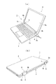
2 第1筐体
3 第2筐体
4 2軸ヒンジ
4a 本体部分
5 2軸ヒンジ
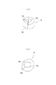
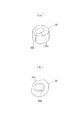
6 ヒンジケース
6b 取付部
6e 取付ネジ
7 ヒンジケース
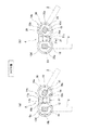
10 第1ヒンジシャフト
12 第2ヒンジシャフト
14 選択的回転規制手段
14a 第1選択的回転規制手段
14b 第2選択的回転規制手段
15 第1連結部材(第1ガイド部材、カムプレート)
15a 第1A軸受孔
15b 第1B軸受孔
15e 第1A湾曲カム凹部
15f 第1B湾曲カム凹部
15g 第2A湾曲カム凹部
15h 第2B湾曲カム凹部
16 第2連結部材(第2ガイド部材、ストッパープレート)
16a 第2A軸受孔
16b 第2B軸受孔
16d 第1ストッパー片
16e 第2ストッパー片
17 第1ロック・解除部材
18 第1Aロックカム部材
18c 第1突起部
19 第1Bロックカム部材
19c 第2突起部
20 第3連結部材(第3ガイド部材、第1フリクションプレート)
20a 第3A軸受孔
20b 第3B軸受孔
21 第2ロック・解除部材
22 第2Aロックカム部材
23 第2Bロックカム部材
24 ストッパー手段
24a 第1ストッパー手段
24b 第2ストッパー手段
25 フリクショントルク発生手段
25a 第1フリクショントルク発生手段
25b 第2フリクショントルク発生手段
26 第4連結部材(第2フリクションプレート)
26a 第4A軸受孔
26b 第4B軸受孔
27 第1フリクションワッシャー
28 第2フリクションワッシャー
31 吸込み手段
31a 第1吸込み手段
31b 第2吸込み手段
32 第1カムフォロワー
32b 第1A湾曲カム凸部
32c 第1B湾曲カム凸部
33 第2カムフォロワー
33b 第2A湾曲カム凸部
33c 第2B湾曲カム凸部
34a 第1弾性手段
34b 第2弾性手段
Claims (6)
- 端末機器の第1筐体と第2筐体を互いに相対的に開閉させる2軸ヒンジであって、前記第1筐体側へ取り付けられる第1ヒンジシャフトと、前記第2筐体側へ取り付けられる第2ヒンジシャフトとを複数の連結部材で平行状態に連結して互いに回転可能に設け、前記第1ヒンジシャフトと前記第2ヒンジシャフトを選択的に回転させる選択的回転規制手段を有するものにおいて、前記選択的回転規制手段を、前記第1ヒンジシャフトと前記第2ヒンジシャフトをそれぞれ回転可能に挿通させて対置させた連結部材の間に上下動可能に設けた第1ロック・解除部材と、この第1ロック・解除部材を挟んで上部側と下部側に前記第1ヒンジシャフトと前記第2ヒンジシャフトにそれぞれ回転を規制されて設けられた第1Aロックカム部材と第1Bロックカム部材とから成る第1選択的回転規制手段と、この第1選択的回転規制手段に隣接して設けたところの前記第1ヒンジシャフトと前記第2ヒンジシャフトをそれぞれ回転可能に挿通させて対置させた連結部材の間に上下動可能に設けた第2ロック・解除部材と、この第2ロック・解除部材を挟んで上部側と下部側に前記第1ヒンジシャフトと前記第2ヒンジシャフトにそれぞれ回転を規制されて設けられた第2Aロックカム部材と第2Bロックカム部材とから成る第2選択的回転規制手段と、で構成し、前記第1選択的回転規制手段と前記第2選択的回転規制手段によって、前記第1筐体と前記第2筐体を所定の順序でその開閉方向を複数段階に切り替えて開閉させて、閉成状態の0°から全開成状態の360°に渡って複数の開成角度毎に開閉できるように成したことを特徴とする、2軸ヒンジ。
- 前記2軸ヒンジは、第1ストッパー手段と第2ストッパー手段とから成るストッパー手段を有し、前記第1ストッパー手段は、前記第1選択的回転規制手段と前記第2選択的回転規制手段のいずれかの連結部材を兼ねるストッパープレートの下部側に設けた第1ストッパー片と、前記第1Aロックカム部材或は第2Aロックカム部材の外周の前記第1ストッパー片と対置する位置に設けた第1突起部とで構成し、前記第2ストッパー手段は、前記連結部材を兼ねるストッパープレートの上部側に設けた第2ストッパー片と、前記第1Bロックカム部材或は第2Bロックカム部材の外周の前記第2ストッパー片と対置する位置に設けた第2突起部と、で構成したことを特徴とする、請求項1に記載の2軸ヒンジ。
- 前記2軸ヒンジは、第1フリクショントルク発生手段と第2フリクショントルク発生手段から成るフリクショントルク発生手段を有し、前記第1フリクショントルク発生手段は、前記連結部材を兼ねる第1フリクションプレートと、この第1フリクションプレートに対向させて設けた他の連結部材を構成する第2フリクションプレートと間に前記第1ヒンジシャフトに回転を規制させて取り付けた第1フリクションワッシャーと、前記第1フリクションプレートと第2フリクションプレートを前記第1フリクションワッシャーを挟んでその両側に圧接させる第1弾性手段とで構成し、前記第2フリクショントルク発生手段は、前記第1フリクションプレートと前記第2フリクションプレートの間に前記第2ヒンジシャフトに回転を規制させて取り付けた第2フリクションワッシャーと、前記第1フリクションプレートと第2フリクションプレートを前記第2フリクションワッシャーを挟んでその両側に圧接させる第2弾性手段とで構成したことを特徴とする、請求項1に記載の2軸ヒンジ。
- 前記2軸ヒンジは、第1吸込み手段と第2吸込み手段から成る吸込み手段を有し、前記第1吸込み手段は、前記第1ヒンジシャフトを回転可能に挿通させて設けたところのカムプレートの軸受孔の周りに設けた第1A湾曲カム凹部及び第1B湾曲カム凹部と、前記第1ヒンジシャフトに回転を規制されて取り付けられ、前記第1A湾曲カム凹部及び第1B湾曲カム凹部と対向する側に第1A湾曲カム凸部及び第1B湾曲カム凸部を有する第1カムフォロワーと、前記第1A湾曲カム凹部及び第1B湾曲カム凹部と前記第1A湾曲カム凸部及び第1B湾曲カム凸部とを圧接する第1弾性手段とで構成し、前記第2吸込み手段は、前記第2ヒンジシャフトを回転可能に挿通させて設けたところの前記カムプレートの軸受孔の周りに設けた第2A湾曲カム凹部及び第2B湾曲カム凹部と、前記第2ヒンジシャフトに回転を規制されて取り付けられ、前記第2A湾曲カム凹部及び前記第2B湾曲カム凹部と対向する側に第2A湾曲カム凸部及び第2B湾曲カム凸部を有する第2カムフォロワーと、前記第2A湾曲カム凹部及び第2B湾曲カム凹部と前記第2A湾曲カム凸部及び第2B湾曲カム凸部とを圧接する第2弾性手段とで構成したことを特徴とする、請求項1に記載の2軸ヒンジ。
- 前記2軸ヒンジは、前記フリクショントルク発生手段の連結部材を兼ねる第1フリクションプレートから先の本体部分に被せるヒンジケースを有し、このヒンジケースはその内部に設けた取付部を前記本体部分に取付ネジを介して着脱可能に取り付けたことを特徴とする、請求項3に記載の2軸ヒンジ。
- 前記請求項1〜5に各記載の2軸ヒンジを用いたことを特徴とする、端末機器。
Priority Applications (3)
| Application Number | Priority Date | Filing Date | Title |
|---|---|---|---|
| JP2014050201A JP6355233B2 (ja) | 2014-03-13 | 2014-03-13 | 2軸ヒンジ及びこの2軸ヒンジを用いた端末機器 |
| CN201510110198.3A CN104912912B (zh) | 2014-03-13 | 2015-03-13 | 双轴铰链及应用此双轴铰链的终端机器 |
| TW104108167A TWI526147B (zh) | 2014-03-13 | 2015-03-13 | 雙軸鉸鏈及應用此雙軸鉸鏈的終端機器 |
Applications Claiming Priority (1)
| Application Number | Priority Date | Filing Date | Title |
|---|---|---|---|
| JP2014050201A JP6355233B2 (ja) | 2014-03-13 | 2014-03-13 | 2軸ヒンジ及びこの2軸ヒンジを用いた端末機器 |
Publications (3)
| Publication Number | Publication Date |
|---|---|
| JP2015175389A JP2015175389A (ja) | 2015-10-05 |
| JP2015175389A5 JP2015175389A5 (ja) | 2017-04-13 |
| JP6355233B2 true JP6355233B2 (ja) | 2018-07-11 |
Family
ID=54082268
Family Applications (1)
| Application Number | Title | Priority Date | Filing Date |
|---|---|---|---|
| JP2014050201A Active JP6355233B2 (ja) | 2014-03-13 | 2014-03-13 | 2軸ヒンジ及びこの2軸ヒンジを用いた端末機器 |
Country Status (3)
| Country | Link |
|---|---|
| JP (1) | JP6355233B2 (ja) |
| CN (1) | CN104912912B (ja) |
| TW (1) | TWI526147B (ja) |
Families Citing this family (13)
| Publication number | Priority date | Publication date | Assignee | Title |
|---|---|---|---|---|
| JP5986156B2 (ja) * | 2014-08-08 | 2016-09-06 | レノボ・シンガポール・プライベート・リミテッド | ヒンジ機構及び電子機器 |
| JP6544734B2 (ja) | 2015-01-14 | 2019-07-17 | 株式会社ナチュラレーザ・ワン | 2軸ヒンジ及びこの2軸ヒンジを用いた電子機器 |
| JP6838721B2 (ja) * | 2016-09-01 | 2021-03-03 | 株式会社ナチュラレーザ・ワン | 多軸ヒンジ並びにこの多軸ヒンジを用いた電子機器 |
| JP6181268B1 (ja) * | 2016-10-21 | 2017-08-16 | 文孝 西岡 | 容器保持具 |
| TWI652414B (zh) * | 2016-11-03 | 2019-03-01 | 緯創資通股份有限公司 | 樞軸模組及組裝方法 |
| CN206918043U (zh) * | 2017-04-19 | 2018-01-23 | 广东欧珀移动通信有限公司 | 转轴组件及可折叠终端 |
| CN107889420B (zh) * | 2017-12-12 | 2023-06-09 | 无锡优耐特能源科技有限公司 | 一种导轨固定件 |
| CN109445526B (zh) * | 2018-11-28 | 2022-04-22 | 联想(北京)有限公司 | 一种电子设备及其驱动机构 |
| CN112888867B (zh) * | 2018-12-28 | 2023-04-18 | 三菱制钢株式会社 | 铰链及电子设备 |
| TWI691826B (zh) | 2019-01-08 | 2020-04-21 | 宏碁股份有限公司 | 電子裝置及其鉸鏈機構 |
| CN111473041B (zh) * | 2019-01-23 | 2022-01-04 | 宏碁股份有限公司 | 电子装置及其铰链机构 |
| TWI694214B (zh) * | 2019-12-09 | 2020-05-21 | 兆利科技工業股份有限公司 | 可交替旋轉的雙軸式鉸鏈(二) |
| WO2021210075A1 (ja) * | 2020-04-14 | 2021-10-21 | 株式会社ナチュラレーザ・ワン | 昇降式2軸ヒンジ並びにこの昇降式2軸ヒンジを用いた端末機器 |
Family Cites Families (7)
| Publication number | Priority date | Publication date | Assignee | Title |
|---|---|---|---|---|
| JP4440189B2 (ja) * | 2005-09-01 | 2010-03-24 | 三菱製鋼株式会社 | 2軸型ヒンジ装置 |
| JP5114136B2 (ja) * | 2007-09-05 | 2013-01-09 | 株式会社 サンコー | チルトヒンジ装置 |
| JP5112121B2 (ja) * | 2008-03-13 | 2013-01-09 | 加藤電機株式会社 | 2軸ヒンジ装置並びに電子機器 |
| CN103291737B (zh) * | 2012-02-22 | 2015-03-04 | 兆利科技工业股份有限公司 | 卡锁式双轴枢纽器 |
| CN202468692U (zh) * | 2012-03-14 | 2012-10-03 | 连鋐科技股份有限公司 | 具限位功能的短轴距双轴式枢钮器 |
| CN202579633U (zh) * | 2012-05-17 | 2012-12-05 | 兆利科技工业股份有限公司 | 滑轮卡锁式双轴枢纽器 |
| JP5704613B2 (ja) * | 2012-05-30 | 2015-04-22 | 株式会社ナチュラレーザ・ワン | 2軸ヒンジ |
-
2014
- 2014-03-13 JP JP2014050201A patent/JP6355233B2/ja active Active
-
2015
- 2015-03-13 TW TW104108167A patent/TWI526147B/zh not_active IP Right Cessation
- 2015-03-13 CN CN201510110198.3A patent/CN104912912B/zh not_active Expired - Fee Related
Also Published As
| Publication number | Publication date |
|---|---|
| TW201536154A (zh) | 2015-09-16 |
| TWI526147B (zh) | 2016-03-11 |
| JP2015175389A (ja) | 2015-10-05 |
| CN104912912A (zh) | 2015-09-16 |
| CN104912912B (zh) | 2017-11-17 |
Similar Documents
| Publication | Publication Date | Title |
|---|---|---|
| JP6355233B2 (ja) | 2軸ヒンジ及びこの2軸ヒンジを用いた端末機器 | |
| JP6338176B2 (ja) | 2軸ヒンジ及びこの2軸ヒンジを用いた端末機器 | |
| JP6324833B2 (ja) | 2軸ヒンジ及びこの2軸ヒンジを用いた端末機器 | |
| JP5704613B2 (ja) | 2軸ヒンジ | |
| JP2015148296A5 (ja) | ||
| JP6338177B2 (ja) | 2軸ヒンジ及びこの2軸ヒンジを用いた端末機器 | |
| KR101937557B1 (ko) | 2축 힌지 및 상기 2축 힌지를 이용한 단말기기 | |
| JP6590135B2 (ja) | 2軸ヒンジ及びこの2軸ヒンジを用いた電子機器 | |
| JP2015155708A5 (ja) | ||
| JP5892573B2 (ja) | 2軸ヒンジ並びにこの2軸ヒンジを用いた端末機器 | |
| JP2005337301A (ja) | ヒンジ装置並びにこのヒンジ装置を用いた電子機器 | |
| JP6388301B2 (ja) | ヒンジ装置並びに情報端末 | |
| JP6525233B2 (ja) | 2軸ヒンジ及びこの2軸ヒンジを用いた端末機器 | |
| JP5892566B2 (ja) | 2軸ヒンジ並びにこの2軸ヒンジを用いた端末機器 | |
| JP2015105693A5 (ja) | ||
| JP2015064105A5 (ja) | ||
| CN107608450B (zh) | 连接装置及电子设备 | |
| JP2013228104A (ja) | ヒンジユニット及びそれを用いた携帯端末 |
Legal Events
| Date | Code | Title | Description |
|---|---|---|---|
| A521 | Request for written amendment filed |
Free format text: JAPANESE INTERMEDIATE CODE: A523 Effective date: 20170308 |
|
| A621 | Written request for application examination |
Free format text: JAPANESE INTERMEDIATE CODE: A621 Effective date: 20170308 |
|
| A131 | Notification of reasons for refusal |
Free format text: JAPANESE INTERMEDIATE CODE: A131 Effective date: 20171017 |
|
| A521 | Request for written amendment filed |
Free format text: JAPANESE INTERMEDIATE CODE: A523 Effective date: 20171218 |
|
| TRDD | Decision of grant or rejection written | ||
| A01 | Written decision to grant a patent or to grant a registration (utility model) |
Free format text: JAPANESE INTERMEDIATE CODE: A01 Effective date: 20180515 |
|
| A61 | First payment of annual fees (during grant procedure) |
Free format text: JAPANESE INTERMEDIATE CODE: A61 Effective date: 20180611 |
|
| R150 | Certificate of patent or registration of utility model |
Ref document number: 6355233 Country of ref document: JP Free format text: JAPANESE INTERMEDIATE CODE: R150 |
|
| R250 | Receipt of annual fees |
Free format text: JAPANESE INTERMEDIATE CODE: R250 |
|
| R250 | Receipt of annual fees |
Free format text: JAPANESE INTERMEDIATE CODE: R250 |
|
| R250 | Receipt of annual fees |
Free format text: JAPANESE INTERMEDIATE CODE: R250 |
|
| R250 | Receipt of annual fees |
Free format text: JAPANESE INTERMEDIATE CODE: R250 |
|
| S531 | Written request for registration of change of domicile |
Free format text: JAPANESE INTERMEDIATE CODE: R313531 |
|
| R350 | Written notification of registration of transfer |
Free format text: JAPANESE INTERMEDIATE CODE: R350 |
|
| R250 | Receipt of annual fees |
Free format text: JAPANESE INTERMEDIATE CODE: R250 |