JP6408384B2 - Root crop harvesting machine - Google Patents
Root crop harvesting machine Download PDFInfo
- Publication number
- JP6408384B2 JP6408384B2 JP2015002546A JP2015002546A JP6408384B2 JP 6408384 B2 JP6408384 B2 JP 6408384B2 JP 2015002546 A JP2015002546 A JP 2015002546A JP 2015002546 A JP2015002546 A JP 2015002546A JP 6408384 B2 JP6408384 B2 JP 6408384B2
- Authority
- JP
- Japan
- Prior art keywords
- leaf
- transmission case
- leaf cutting
- transmission
- root
- Prior art date
- Legal status (The legal status is an assumption and is not a legal conclusion. Google has not performed a legal analysis and makes no representation as to the accuracy of the status listed.)
- Active
Links
Images








Landscapes
- Harvesting Machines For Root Crops (AREA)
Description
本発明は、人参や大根等の根菜を収穫するための根菜収穫機に関する。 The present invention relates to a root vegetable harvesting machine for harvesting root vegetables such as carrots and radishes.
従来の根菜収穫機では、機体の走行に伴って圃場から根菜を引き抜いて機体後方側に搬送するベルト搬送式の引き抜き装置と、その引き抜き装置にて後方側に搬送される根菜の葉部を分離する葉切り装置とが備えられている。葉切り装置は、引き抜き装置によって搬送される根菜に対して根菜の上端部の位置を合わせる位置合わせ用の無端回動チェーンと、位置合わせした根菜の葉部を挟持しながら後方に搬送する搬送ベルトと、搬送しながら葉部における根菜との境界付近を切断する回転式カッタとを備える構成となっている。そして、エンジンからの動力を葉切り装置の各装置に分岐伝達するための伝動機構が伝動ケースに内装される状態で備えられ、その伝動ケースが、葉切り装置の下方側に位置する状態で備えられていた(例えば、特許文献1参照)。 In conventional root vegetable harvesting machines, a belt-conveying drawing device that pulls out root vegetables from the field and transports them to the rear side of the machine as the machine runs, and a leaf portion of the root vegetables that is conveyed rearward by the drawing device is separated. And a leaf cutting device. The leaf cutting device includes an endless rotating chain for aligning the position of the upper end of the root vegetable with respect to the root vegetable conveyed by the pulling device, and a conveyor belt that conveys the root vegetable leaf to the rear while sandwiching the aligned root vegetable leaf portion. And a rotary cutter that cuts the vicinity of the boundary with the root vegetables in the leaf portion while being conveyed. A transmission mechanism for branching and transmitting the power from the engine to each device of the leaf cutting device is provided in the transmission case, and the transmission case is provided in a state of being located below the leaf cutting device. (For example, refer to Patent Document 1).
上記根菜収穫機では、搬送ベルトによって搬送される根菜は、搬送ベルトによって葉部が挟持されて搬送され、回転式カッタにより葉部と根菜との境界付近が切断されるものであるから、葉切り装置よりも下方側に根菜が位置している状態で搬送される。そして、伝動ケースが、葉切り装置の下方側に位置する状態で備えられるので、搬送される根菜の横側に伝動ケースが位置することになる。 In the root vegetable harvesting machine, the root vegetables transported by the transport belt are transported with the leaf portion sandwiched by the transport belt, and the vicinity of the boundary between the leaf portion and the root vegetable is cut by the rotary cutter. It is transported in a state where root vegetables are located below the apparatus. And since a transmission case is prepared in the state located in the downward side of a leaf cutting device, a transmission case will be located in the side of the root vegetable conveyed.
しかし、根菜は土中から引き抜かれるので、収穫された根菜には土が付着しており、又、収穫作業に伴う機体の振動に伴って搬送される根菜が左右に揺れ動くことがある。その結果、伝動ケースの表面に土が付着することがあり、このような土が付着堆積して量が多くなると、根菜の搬送が阻害されて、根菜の収穫作業が良好に行えなくなるおそれがある。 However, since the root vegetables are pulled out from the soil, the soil is attached to the harvested root vegetables, and the root vegetables transported may swing from side to side in accordance with the vibration of the machine accompanying the harvesting operation. As a result, soil may adhere to the surface of the transmission case, and if such soil adheres and accumulates and the amount increases, the transport of root vegetables may be hindered and root vegetables may not be harvested well. .
そこで、伝動ケースへの土の付着を防止して、収穫作業を良好に行えるようにすることが望まれていた。 Therefore, it has been desired to prevent the soil from adhering to the transmission case so that the harvesting operation can be performed satisfactorily.
本発明に係る根菜収穫機の特徴構成は、機体の走行に伴って圃場から根菜を引き抜いて機体後方側に搬送する引き抜き装置と、複数の回動体を備えて前記引き抜き装置にて後方側に搬送される根菜の葉部を分離する葉切り装置と、エンジンから伝達される動力を前記葉切り装置の複数の回動体に分岐伝達する伝動機構を内装するとともに前記葉切り装置よりも上方側に配備された葉切り用伝動ケースとを備えており、前記葉切り装置は、複数の回動体として、根菜を上下方向に位置決めする位置決め用の無端回動体と、根菜を後方に搬送する分離用の無端回動体と、前記分離用の無端回動体により搬送される根菜に対して根菜と葉部とを切断して分離する切断装置とを備え、前記位置決め用の無端回動体、前記分離用の無端回動体、及び、前記切断装置の夫々が、前記葉切り用伝動ケースの下方側に備えられており、前記葉切り用伝動ケースが、根菜の搬送経路の左右両側に夫々各別に備えられ、前記葉切り装置において前記分離用の無端回動体により搬送される根菜の葉部が通過する領域の左右両側を覆う左右一対の側部カバー体が、左右両側の前記葉切り用伝動ケースに夫々支持されており、前記左右一対の側部カバー体は、それぞれ、正面視において、上下方向に延びる部位と、前記上下方向に延びる部位の上端部から外側に延びる部位と、を有しており、前記左右一対の側部カバー体における上下方向に延びる部位は、それぞれ、正面視において、左右の前記葉切り用伝動ケースの間に位置している点にある。 The characteristic configuration of the root vegetable harvesting machine according to the present invention includes a pulling device that pulls out a root vegetable from the field and transports it to the rear side of the machine as the machine runs, and a plurality of rotating bodies that are transported rearward by the pulling device. A leaf cutting device that separates the leaf portion of the root vegetables and a transmission mechanism that branches and transmits the power transmitted from the engine to a plurality of rotating bodies of the leaf cutting device and is disposed above the leaf cutting device The leaf cutting device includes, as a plurality of rotating bodies, an endless rotating body for positioning the root vegetables in the vertical direction and an endless separation for conveying the root vegetables rearward. A rotating body, and a cutting device that cuts and separates the root vegetables and leaf parts from the root vegetables conveyed by the endless rotating body for separation, the endless rotating body for positioning, and the endless rotation for separation Moving body and front Each of the cutting devices is provided on the lower side of the leaf cutting transmission case, and the leaf cutting transmission case is provided separately on each of the left and right sides of the root vegetable conveyance path, and the separation is performed in the leaf cutting device. A pair of left and right side cover bodies covering both the left and right sides of the region through which the root part of the root vegetable conveyed by the endless rotating body for use is supported by the leaf cutting transmission cases on the left and right sides, respectively, Each of the side cover bodies has a part extending in the vertical direction and a part extending outward from the upper end of the part extending in the vertical direction in front view, and the pair of left and right side cover bodies The parts extending in the vertical direction are respectively located between the left and right leaf cutting transmission cases in a front view .
本発明によれば、葉切り装置は、複数の回動体を備えており、伝動機構によってエンジンから伝達される動力が複数の回動体に分岐伝達されて、引き抜き装置にて後方側に搬送される根菜の葉部を分離する。そして、伝動機構を内装する葉切り用伝動ケースが葉切り装置よりも上方側に位置する状態で配備される。 According to the present invention, the leaf cutting device includes a plurality of rotating bodies, and the power transmitted from the engine by the transmission mechanism is branched and transmitted to the plurality of rotating bodies and conveyed to the rear side by the drawing device. Separate root leaf. And the transmission case for leaf cutting which incorporates a transmission mechanism is deployed in the state located in the upper side rather than a leaf cutting device.
このように構成することで、葉切り装置によって搬送される根菜が葉切り装置よりも下方に位置する状態で搬送されても、根菜に付着している土が葉切り用伝動ケースに付着して堆積するおそれが少ない。その結果、根菜の移動経路が閉塞されたり、経路が狭くなって根菜の搬送並びにそれに伴う葉部の切断処理が阻害される等のおそれが少ないものとなる。 By comprising in this way, even if the root vegetable conveyed by the leaf cutting device is conveyed in a state positioned below the leaf cutting device, the soil adhering to the root vegetable adheres to the leaf cutting transmission case. There is little possibility of accumulation. As a result, the movement route of root vegetables is blocked, or the route is narrowed, so that there is less possibility that the conveyance of root vegetables and the accompanying cutting processing of the leaf portion will be hindered.
従って、葉切り用伝動ケースへの土の付着を防止して、収穫作業を良好に行えるようにすることが可能となった。 Therefore, it has become possible to prevent the soil from adhering to the leaf cutting transmission case and to perform the harvesting work satisfactorily.
また、本構成によれば、葉切り装置においては、引き抜き装置にて後方側に搬送される根菜が位置決め用の無端回動体によって上下方向に位置決めされる。位置決めされた根菜を分離用の無端回動体によって後方に搬送しながら、切断装置によって根菜と葉部とを切断して分離する。このように分離用の無端回動体によって搬送することでしっかりと保持された状態で良好に葉部を切断することができる。尚、分離された根菜は別途回収され、葉部は外方に排出される。 Moreover, according to this structure, in the leaf cutting device, the root vegetables conveyed to the rear side by the drawing device are positioned in the vertical direction by the endless rotating body for positioning. While the positioned root vegetables are conveyed backward by an endless rotating body for separation, the root vegetables and leaf portions are cut and separated by a cutting device. Thus, a leaf part can be cut | disconnected favorably in the state hold | maintained firmly by conveying by the endless rotation body for isolation | separation. The separated root vegetables are collected separately, and the leaves are discharged outward.
そして、位置決め用の無端回動体、分離用の無端回動体、及び、切断装置の夫々が、葉切り用伝動ケースの下方側に備えられるので、切断位置よりも下側に位置する根菜は、葉切り用伝動ケースに接触することがなく、葉切り用伝動ケースに土が付着するおそれは少ないものとなる。 And since each of the endless rotating body for positioning, the endless rotating body for separation, and the cutting device is provided below the transmission case for leaf cutting, the root vegetables positioned below the cutting position are There is no possibility of soil adhering to the leaf cutting transmission case without touching the cutting transmission case.
また、本構成によれば、根菜を搬送する搬送処理や、葉部を切断する切断処理等を行う場合、根菜の搬送経路の左右両側に夫々各別に葉切り用伝動ケースを備えて、搬送経路の左右両側に回動体を備えることによって、それらの処理を良好に行うことができる。そして、このように左右両側に備えられる葉切り用伝動ケースを有効に利用することで、専用の支持部材を別途備える等の構成の複雑化を招くことなく、左右一対の側部カバー体を支持することができる。 In addition, according to the present configuration, when performing a transport process for transporting root vegetables, a cutting process for cutting leaves, etc., the leaf cutting transmission case is provided on each of the left and right sides of the root vegetable transport path. By providing the rotating bodies on both the left and right sides, it is possible to perform these processes satisfactorily. And by effectively utilizing the leaf cutting transmission cases provided on the left and right sides in this way, the pair of left and right side cover bodies are supported without complicating the configuration such as separately providing a dedicated support member. can do.
本発明においては、前記葉切り用伝動ケースから下向きに突出する状態で複数の伝動軸が備えられ、前記位置決め用の無端回動体、前記分離用の無端回動体、及び、前記切断装置の夫々が前記伝動軸に支持されていると好適である。 In the present invention, a plurality of transmission shafts are provided in a state of projecting downward from the leaf cutting transmission case, and each of the positioning endless rotating body, the separating endless rotating body, and the cutting device includes: It is preferable that it is supported by the transmission shaft.
本構成によれば、葉切り用伝動ケースから下向きに突出する伝動軸によって、位置決め用の無端回動体、分離用の無端回動体、及び、切断装置の夫々を良好に支持することができる。つまり、上方側に位置する葉切り用伝動ケースによって葉切り装置を支持することができ、別の支持部材を備える必要がないので、根菜の搬送が邪魔されることなく葉切り処理を良好に行うことができる。 According to this configuration, the endless rotating body for positioning, the endless rotating body for separation, and the cutting device can be favorably supported by the transmission shaft that protrudes downward from the transmission case for leaf cutting. That is, the leaf cutting device can be supported by the leaf cutting transmission case located on the upper side, and it is not necessary to provide another support member, so that the leaf cutting process is performed well without disturbing the conveyance of root vegetables. be able to.
本発明においては、前記葉切り用伝動ケースが、根菜の搬送経路の左右両側に夫々各別に備えられ、前記エンジンからの動力を左右両側の前記葉切り用伝動ケースに内装された左右両側の伝動機構に夫々伝達する中継伝動機構が、前記葉切り装置の下方側に位置して左右方向に延びる中継伝動ケースに内装される状態で備えられ、前記左右両側の前記葉切り用伝動ケースは、前記中継伝動ケースを介して、主フレームに支持されていると好適である。 In the present invention, the leaf cutting transmission cases are provided separately on the left and right sides of the root vegetable conveyance path, respectively, and the power from the engine is mounted on the left and right sides of the leaf cutting transmission cases. A relay transmission mechanism for transmitting to each mechanism is provided in a state of being installed in a relay transmission case located on the lower side of the leaf cutting device and extending in the left-right direction, and the leaf cutting transmission cases on the left and right sides are It is preferable that the main frame is supported via the relay transmission case.
本構成によれば、中継伝動機構を介してエンジンからの動力が左右両側の伝動機構に夫々伝達される。そして、中継伝動機構を内装する中継伝動ケースを有効に利用して、別の支持部材を別途備える等の構成の複雑化を招くことなく、左右両側の葉切り用伝動ケースを主フレームに支持させることができる。又、葉切り装置は左右両側の葉切り用伝動ケースにて支持される。 According to this configuration, the power from the engine is transmitted to the left and right transmission mechanisms via the relay transmission mechanism. Then, by effectively using the relay transmission case that houses the relay transmission mechanism, the left and right leaf cutting transmission cases are supported by the main frame without complicating the configuration such as separately providing another support member. be able to. The leaf cutting device is supported by a leaf cutting transmission case on both the left and right sides.
従って、左右両側の葉切り用伝動ケース及び葉切り装置を主フレームにて安定的に支持することができる。 Accordingly, the leaf cutting transmission case and the leaf cutting device on both the left and right sides can be stably supported by the main frame.
本発明においては、前記葉切り装置により分離されて前記葉切り装置の後端部から排出される葉部を機体外方側に流下案内する案内板が備えられ、前記案内板が前記中継伝動ケースに支持されていると好適である。 In the present invention, there is provided a guide plate that guides the leaf portion separated by the leaf cutting device and discharged from the rear end portion of the leaf cutting device to the outside of the machine body, and the guide plate is the relay transmission case. It is preferable that it is supported by.
本構成によれば、葉切り装置により分離された葉部を案内板によって機体外方側に流下案内するので、葉部が機体内に堆積して収穫作業の邪魔になる等のおそれがない。案内板は、葉部を有効に案内するために左右方向に幅広に形成することが望ましいが、左右方向に延びる中継伝動ケースを有効に利用することで、案内板を左右方向に幅広に形成する場合であっても、案内板を安定的に支持することができる。 According to this configuration, since the leaf portion separated by the leaf cutting device is guided down to the outside of the machine body by the guide plate, there is no possibility that the leaf part accumulates in the machine body and interferes with the harvesting operation. The guide plate is preferably formed wide in the left-right direction in order to effectively guide the leaf portion, but the guide plate is formed wide in the left-right direction by effectively using the relay transmission case extending in the left-right direction. Even in this case, the guide plate can be stably supported.
本発明においては、前記引き抜き装置に、根菜の搬送経路の左右両側に位置する一対の引き抜き用無端回動体が備えられ、前記中継伝動ケースの左右両側端部から前記一対の引き抜き用無端回動体の夫々に動力伝達する左右一対の縦向き伝動軸が備えられ、前記縦向き伝動軸を夫々内装する左右一対の縦向き伝動ケースが、前記中継伝動ケースと前記引き抜き装置の支持フレームとにわたって連結され、前記引き抜き装置が、前記縦向き伝動ケース及び前記中継伝動ケースを介して前記主フレームに支持されていると好適である。 In the present invention, the pulling device is provided with a pair of pulling endless rotating bodies positioned on the left and right sides of the root vegetable conveyance path, and the pair of pulling endless rotating bodies are connected to the relay transmission case from the left and right side ends. A pair of left and right vertical transmission shafts for transmitting power to each other are provided, and a pair of left and right vertical transmission cases each having the vertical transmission shaft are respectively connected to the relay transmission case and a support frame of the extraction device, It is preferable that the drawing device is supported by the main frame via the vertical transmission case and the relay transmission case.
本構成によれば、中継伝動ケースの左右両側端部から左右一対の縦向き伝動軸を介して一対の引き抜き用無端回動体の夫々に動力伝達される。そして、縦向き伝動軸を内装する左右一対の縦向き伝動ケースを有効利用して、左右両側の引き抜き装置を主フレームに、安定的に支持させることができる。 According to this configuration, power is transmitted from the left and right end portions of the relay transmission case to the pair of pulling endless rotating bodies via the pair of left and right longitudinal transmission shafts. Then, the left and right pulling devices can be stably supported on the main frame by effectively using a pair of left and right vertical transmission cases that have a vertical transmission shaft.
以下、図面に基づいて、本発明に係る根菜収穫機の実施形態を根菜の一例としての人参を収穫するための人参収穫機に適用した場合について説明する。 Hereinafter, the case where the embodiment of the root vegetable harvester according to the present invention is applied to a carrot harvester for harvesting carrots as an example of root vegetables will be described based on the drawings.
〔全体構成〕
図1,2に示すように、根菜収穫機の一例である人参収穫機は、左右一対のクローラ走行装置1にて支持されている機体フレーム2を備え、且つ、エンジン3の動力により自走する走行機体4を備えている。そして、この走行機体4に、運転座席5を備えた搭乗運転部6、機体走行に伴って圃場から根菜の一例である人参aを引き抜いて機体後方に搬送する収穫部7、収穫部7にて後方に搬送される人参の葉部を切断して作物と分離して排出する葉部分離部8、葉部が切断された作物を受け止めて後方に搬送するベルトコンベア9、ベルトコンベア9から送り出される人参を機体横側上方に向けて搬送する横送りコンベア10、この横送りコンベア10からの人参aを回収袋11によって回収する回収部12等を備えている。
〔overall structure〕
As shown in FIGS. 1 and 2, a carrot harvester, which is an example of a root vegetable harvester, includes a
収穫部7及び葉部分離部8は、それらが一体的に、機体前後方向に延びる角パイプ材からなる左右一対の主フレーム13を介して、機体フレーム2に対して横軸芯P1周りで揺動自在に支持されている。そして、主フレーム13の前後途中部と機体フレーム2とにわたって枢支連結された油圧シリンダ14により昇降操作自在に支持されている。
The
〔収穫部〕
収穫部7は、機体走行に伴って列状に植え付けられている人参の植付列の左右両側にて人参aの葉部を引き起こす左右両側の引起し装置15,16、人参aの横側の土中に入り込ませて振動付与によって土をほぐす土ほぐし装置17と、人参aの葉部bを挟持して圃場から人参を引き抜いて機体後方側に搬送する引き抜き装置18と、引き抜き装置18の搬送途中の下方に位置して人参aの下端のひげ根を切断するひげ根切断装置19とを備えている。
[Harvesting department]
The
引起し装置15,16は、圃場に植生している人参aの葉部bを上昇移動する引起し爪15a,16aによって梳き上げることにより、収穫対象の人参の葉部を非収穫対象の人参の葉部と分離させて引起こし処理する。
The pulling
左側の引起し装置15は、引起し爪15aが、横軸芯周りで回動する無端回動チェーン15bに前方に先端側が突出する状態で備えられて、植え付けられている人参aの左側に作用するように、引起しケース15cの前面側を上昇移動する縦回し式に構成されている。又、右側の引起し装置16は、引起し爪16aが、前後軸芯周りで回動する無端回動チェーン16bに横側方に向けて先端側が突出する状態で備えられて、植え付けられている人参aの右側に作用するように、引起しケース16cの左横側箇所を上昇移動する横回し式に構成されている。
The pulling
土ほぐし装置17は、左右一対の土ほぐし刃17aを備え、この一対の土ほぐし刃17aを駆動によって振動させながら収穫対象の人参aの横側で土壌内を突き進み、引き抜き装置18が人参aを圃場から抜き上げる際に人参aが土壌から抜け出やすいように土壌をほぐしていく。
The
引き抜き装置18は、人参通過経路の左右両側の前面側が前カバー18aにて覆われるとともに、その前カバー18aの後方側において、搬送始端部が引起し装置15,16の後側近くに位置し、搬送終端側ほど機体後方上方に向かう後上り傾斜姿勢の左右一対の無端回動式の搬送ベルト18bが回動自在に備えられている。この左右一対の搬送ベルト18bにより、収穫対象の人参aを圃場から抜き上げるとともに、そのまま引き続いて葉部を挟持して吊り下げ姿勢で機体後方上方に向けて搬送していく。
The pulling
左右一対の搬送ベルト18bは、上部側に位置する駆動プーリ18cと、下部側に位置する従動プーリ18dとに亘って巻回され、駆動プーリ18cに動力が伝達されて駆動される。駆動プーリ18c、従動プーリ18d等は、左右の前カバー18aの後面側に夫々備えられた支持フレーム18fにより支持されている。
The pair of left and right conveying
次に、ひげ根切断装置19について説明する。
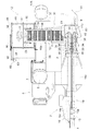
図1に示すように、ひげ根切断装置19は、引き抜き装置18の搬送始端側の下方に位置する箇所において、左右一対の主フレーム13により支持されている。
Next, the hair
As shown in FIG. 1, the
ひげ根切断装置19は、引き抜き装置18によって搬送される人参aの下端のひげ根を機体横向きの軸芯P2周りで回転することにより切り落とす一対の回転刃20と、回転刃20を機体横向き軸芯P2周りで駆動回転する回転刃駆動用の電動モータ21と、回転刃20の移動経路の外周側に位置し、引き抜き装置18によって搬送される人参aの下端部を回転刃20に案内するとともに人参下端部の回転刃移動経路への入り込み長さを規制する案内部22とを備えている。一対の回転刃20は、連結部23により一体的に連結されている。
The hair
案内部22は、引き抜き装置18によって搬送される人参aの通過箇所における左右両側に位置する一対のガイド部材22R,22Lを備えており、左側に位置する一方のガイド部材22Lが回転式ガイド部材として構成され、右側に位置する他方のガイド部材22Rが固定式ガイド部材として構成されている。
The
図3,5に示すように、右側の主フレーム13の側面に連結固定されたブラケット24に回転刃駆動用の電動モータ21の本体が取り付け支持されており、この回転刃駆動用の電動モータ21の出力軸21aに一対の回転刃20を連結する連結部23が一体回転すべく連結固定されている。又、ブラケット24に固定式ガイド部材22Rが一体的に連結されている。
As shown in FIGS. 3 and 5, the main body of the
回転刃駆動用の電動モータ21は、人参aのひげ根を切断することができるように高速で一対の回転刃20を駆動するように構成され、且つ、引き抜き装置18による人参aの搬送方向とは反対方向に向けて回転するように回転方向が設定されている。
The
図3,5に示すように、固定式ガイド部材22Rは、丸棒材を円弧状に湾曲形成した円弧状のガイド杆25と、その円弧状のガイド杆25から径方向外方に向けて直線状に延出された直線状のガイド杆26とを備えている。円弧状のガイド杆25は、回転刃20の移動軌跡の径方向外方側にて同心円状に設けられている。
As shown in FIGS. 3 and 5, the fixed
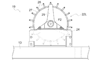
図3,4に示すように、回転式ガイド部材22Lは、左側の主フレーム13の側面に連結固定されたブラケット24に支持されている。この回転式ガイド部材22Lは、丸棒材を円環状に湾曲形成した円環状ガイド杆27と、この円環状ガイド杆27における人参aの通過箇所とは反対側において、周方向に適宜間隔をあけて径方向外方に片持ち状に延設された直線状のガイド杆28とを備えている。円環状ガイド杆27は、回転刃20の回転軌跡の径方向外方側にて同心円状に設けられている。
As shown in FIGS. 3 and 4, the
回転式ガイド部材22Lは、周方向に間隔をあけた3箇所の直線状のガイド杆28にわたる状態で連結された支持部材29がブラケット24に対して横軸芯P2周りで相対回転自在に支持されている。つまり、回転式ガイド部材22Lは自由回転状態で主フレーム13に支持されている。
The
そして、回転式ガイド部材22Lにおける円環状ガイド杆27と、固定式ガイド部材22Rにおける円弧状のガイド杆25とが、機体横幅方向に設定間隔をあけて並ぶ状態で配備されており、それらの間にて形成された隙間を通して人参aの下端部を回転刃20に案内することで、回転刃20によるひげ根の切断処理を良好に行うことができる。
An
固定式ガイド部材22R及び回転式ガイド部材22Lは、夫々、丸棒材からなる複数の直線状のガイド杆26,28を間隔をあけて設けることにより、直線状のガイド杆26,28同志の間に泥抜き用開口部が形成される。つまり、人参aに付着している泥土が降りかかることがあっても、この泥抜き用開口部を通して排出させることができる。又、回転式ガイド部材22Lが人参との摺接等によって自由回転することによって、付着しかかった泥土が振り落とされて、泥土が付着堆積することを未然に防止できる。
The fixed
〔葉部分離部〕
次に、葉部分離部8について説明する。
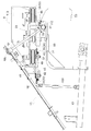
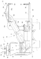
図6〜10に示すように、葉部分離部8は、複数の回動体30を備えて、引き抜き装置18にて後方側に搬送される人参aの葉部bを分離する葉切り装置31と、エンジン3から伝達される動力を葉切り装置31の複数の回動体30に分岐伝達する伝動機構32を内装するとともに葉切り装置31よりも上方側に配備された葉切り用伝動ケース33とを備えている。
(Leaf separation part)
Next, the leaf
As shown in FIGS. 6 to 10, the leaf
葉切り装置31は、複数の回動体30として、人参aを上下方向に位置決めする位置決め用の無端回動体としての位置決め用無端回動チェーン(以下、位置決めチェーンと略称する)34と、人参aを後方に搬送する分離用の無端回動体としての分離用の無端回動ベルト(以下、分離用ベルトと略称する)35、分離用ベルト35により搬送しながら葉部bと人参aとを切断して分離する切断装置としての回転カッタ36を備えている。そして、これら位置決めチェーン34、分離用ベルト35、及び、回転カッタ36の夫々が、葉切り用伝動ケース33の下方側に備えられている。
The
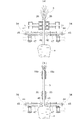
図15に示すように、位置決めチェーン34、分離用ベルト35、回転カッタ36、及び、葉切り用伝動ケース33の夫々が、引き抜き装置18にて後方側に搬送される人参aの搬送経路の左右両側に夫々、各別に備えられている。そして、図7に示すように、葉切り用伝動ケース33から下向きに突出する状態で複数の伝動軸37,38,39が備えられ、位置決めチェーン34、分離用ベルト35、回転カッタ36の夫々が、伝動軸37,38,39に支持されている。
As shown in FIG. 15, the
すなわち、位置決めチェーン34は、左右の葉切り用伝動ケース33から下向きに突出する伝動軸としての第1伝動軸37に取付けた駆動スプロケット40と、左右の葉切り用伝動ケース33の前部に一体的に連結された連結ブラケット41から下向きに突出する伝動軸42に回転自在に取付けた従動スプロケット43とにわたって巻回されている。
That is, the
図10,11に示すように、左右の位置決めチェーン34は、それぞれのリンクプレート44に、移送経路と交差する方向に摺動自在に支持されたスライドロッド45と、スライドロッド45の先端側に回転自在に支持された案内ローラ46と、スライドロッド45を外方側に向けて移動付勢する挟持バネ47とを備えている。
As shown in FIGS. 10 and 11, the left and
左右の位置決めチェーン34は、引き抜き装置18が持ち上げ搬送していく人参aの葉部bの引き抜き装置18の搬送ベルト18bが挟持している部分と人参aとの間を挟み込むように作用する。
The left and
人参aが左右の位置決めチェーン34の間に入り込んだ後も引き抜き装置18は人参aを持ち上げ搬送していき、左右の位置決めチェーン34によって葉部bを挟持しながら吊り下げ姿勢で回転カッタ36の方に移送していく。このとき、挟持バネ47によって発揮する挟持力が、引き抜き装置18が備えている挟持力よりも小さく設定されている。
Even after the carrot a has entered between the left and
従って、引き抜き装置18により人参aが搬送されるに伴って、人参aは左右の案内ローラ46の間に入り込んでから後方に移送される。そのとき、人参aは案内ローラ46に対して上昇操作され、位置決めチェーン34の搬送終端側では、図11(b)に示すように、人参aの上端が案内ローラ46に接当してこの案内ローラ46が人参aに対してそれ以上は上昇しないようにストッパーとして作用する。
Therefore, as the carrot a is transported by the
人参aが回転カッタ36に供給されてその葉部bが切断される際には、人参aの上端からわずかに上側に離れている部分で切断されるように、人参aが回転カッタ36に供給される際の人参aの回転カッタ36に対する位置決めが行われる。
When the carrot a is supplied to the
図7,15に示すように、分離用ベルト35は、左右の葉切り用伝動ケース33の機体後部側から下向きに突出する伝動軸としての第2伝動軸38に取付けた駆動プーリ48と、第1伝動軸37に自由回転自在に支持された従動プーリ49とにわたって巻回されている。分離用ベルト35の搬送始端側は、引き抜き装置18の搬送終端部の下方で、位置決めチェーン34の搬送終端部の上方に位置している。
As shown in FIGS. 7 and 15, the
つまり、分離用ベルト35は、位置決めチェーン34による位置決めが完了した後の人参aの葉部bを引き抜き装置18と位置決めチェーン34とから受け継いで挟持し、機体後方向きに吊り下げ姿勢で搬送して左右の回転カッタ36の間に供給する。そして、回転カッタ36によって切断されて人参aから離れた排葉をそのまま挟持してさらに機体後方向きに搬送して回転カッタ36の後方で挟持を解除する。
In other words, the
図7,15に示すように、回転カッタ36は、左右の葉切り用伝動ケース33の機体後部側から下向きに突出する伝動軸としての第3伝動軸39に一体回転するように取付けられている。左右両側の回転カッタ36は、分離用ベルト35により挟持搬送される人参aの葉部bを適切に切断することができるように、一部が重複する状態で備えられている。
As shown in FIGS. 7 and 15, the
葉部分離部8にて葉部bから切り離された人参aは下方のベルトコンベア9上に落下し、切断された葉部bは分離用ベルト35によって後方に搬送したのち、案内体としての案内シュート50によってベルトコンベア9の搬送終端側に向けて流下案内して、機体後方の圃場に落下させる。
The carrot a separated from the leaf part b by the leaf
図2,15に示すように、ベルトコンベア9の搬送途中部の上方に回転駆動式のガイドローラ51が備えられている。このガイドローラ51は、横送りコンベア10側に位置する方の端が反対側の端よりもベルトコンベア9の搬送下手側に位置するように、回転軸芯がベルトコンベア9の搬送方向に対して傾斜した姿勢で設けられ、ベルトコンベア9が搬送してきた人参aを横外側に移動するように案内して横送りコンベア10に移動させる。
As shown in FIGS. 2 and 15, a rotationally driven
横送りコンベア10は、図示はしないが、コンベアフレーム10aにて支持される前後両側の無端回動チェーンにわたって機体横方向に並ぶ複数本の載置用棒体10bを備え、ベルトコンベア9からの人参aを走行機体4の右側方で且つ斜め上方に向けて載置搬送して回収部12に供給する。図2の10Aは、目視で選別作業する補助作業者が着座する補助座席である。
Although not shown in the drawings, the
回収部12は、横送りコンベア10の搬送終端部の下方に位置させる容器受けの支持台52と、横送りコンベア10の終端部に設けた容器支持部53とを備えている。上端部に開口54を備えるよう縫製された布で成る容器55が、底部側を支持台52によって受け止め支持する状態で、上部開口側を容器支持部53によって吊り下げ支持する状態で、横送りコンベア10の下方に設置されている。
The
図13,14に示すように、容器支持部53は、コンベアフレーム10aに連結アーム56を介して連結された前後向きの支持杆57と、この支持杆57の両端部に支持されるハンガー体58とを備えている。各ハンガー体58は、これの両端部に設けた吊り下げ具59を備えている。
As shown in FIGS. 13 and 14, the
容器支持部53は、一方のハンガー体58の両吊り下げ具59を容器55が備える一対の吊り上げベルト60の一方に係止させ、他方のハンガー体58の両吊り下げ具59を容器55の他方の吊り上げベルト60に係止させることにより、容器55の開口側を吊り下げ支持する。容器55の開口縁部を各ハンガー体58のロッド部58aに止着具61を利用するなどによって止着させることにより、容器支持部53は、容器55の開口54を適正な開き状態に保形する。
The
横送りコンベア10は基端側の機体前後方向に沿う軸芯P3周りで回動自在に支持されている。横送りコンベア10の下側に昇降用油圧シリンダ62が枢支連結され、この昇降用油圧シリンダ62を伸縮作動させることで、横送りコンベア10の搬送終端部を昇降調整することができ、人参aが横送りコンベア10から容器55内に落下することによる人参の損傷を回避しながら人参回収を行うことができる。
The
図示はしていないが、作業開始時には、昇降用油圧シリンダ62を下降側に駆動操作して横送りコンベア10の搬送終端側部を下降調節し、支持台52からの高さを低く調節する。又、容器55に回収された人参群の上面レベルが高くなって容器55の収容空間が減少すると、昇降用油圧シリンダ62を上昇側に駆動操作して横送りコンベア10の搬送終端部を回収開始時よりも上昇調節する。
Although not shown, at the start of the operation, the lifting
支持台52は、この支持台52よりも機体前方側に位置する補助台63の後端部に備えた一対の支持部64に揺動自在に枢支されており、操作アーム部65と補助台63の支持アーム66とに連結されたモータ駆動式のシリンダ機構67によって軸芯P4まわりに補助台63に対して揺動昇降操作される。
The
シリンダ機構67が備える電動モータ68が駆動されると、シリンダ機構67が電動モータ68によって伸長側に駆動されて操作アーム部65を軸芯P4まわりに機体後方側に揺動操作する。これにより、支持台52は、図13に二点鎖線で示す如く横軸芯P4まわりに後下がりのシュート姿勢に下降操作され、容器55を支持台52から降ろしやすくする。
When the
〔伝動構造〕
次に、伝動構造について説明する。
図15に示すように、搭乗運転部6の下方側に備えられたエンジン3の動力が、第1伝動ベルト69、第1中間伝動軸70、第2伝動ベルト71を介して横向きの第2中間伝動軸72に伝達される。第2中間伝動軸72の動力は、ベルトコンベア9、横送りコンベア10、ガイドローラ51に伝達される。又、第2中間伝動軸72の動力は、第3伝動ベルト73、第3中間伝動軸74、ベベルギア機構75、第4中間伝動軸76、ベベルギア機構77を介して土ほぐし装置17に対する振動装置78に伝達され、さらに、第5中間伝動軸79、ベベルギア機構80、前後向きの第6中間伝動軸81を介して右側の引起し装置16に伝達される。又、ベベルギア機構82を介して左側の引起し装置15にも伝達される。
[Transmission structure]
Next, the transmission structure will be described.
As shown in FIG. 15, the motive power of the engine 3 provided on the lower side of the boarding operation unit 6 is transmitted through the
又、エンジン3の動力は、伝動ベルト83を介して走行ミッション84の主変速部である静油圧式の無段変速装置85に伝達され、走行ミッション84を介して左右の走行装置1に伝達される。無段変速装置85の変速後の動力が、伝動ベルト86及び横向きの第7中間伝動軸87を介して、葉切り装置31及び引き抜き装置18に動力が伝達される。
The power of the engine 3 is transmitted to the hydrostatic continuously
すなわち、第7中間伝動軸87の左側の軸端部から、ベベルギア機構88及び縦向き中継伝動軸89を介して中継伝動機構90に動力が伝達される。図9に示すように、中継伝動機構90は、葉切り装置31の下方側に位置して左右方向に延びる中継伝動ケース91に内装される状態で備えられ、エンジン3からの動力を、左右両側の引き抜き装置18、並びに、左右両側の葉切り用伝動ケース33に内装された左右両側の葉切り用伝動機構32に夫々伝達する機能を有する。
That is, power is transmitted from the left end of the seventh
第7中間伝動軸87は、主フレーム13の揺動軸芯P3と同一軸芯上に位置している。縦向き中継伝動軸89を内装する縦向きケース92の下端部は、左側の主フレーム13の揺動支点位置に対応する箇所に連結されており、主フレーム13と一体的に横軸芯P3周りで揺動自在に設けられている。
The seventh
縦向きケース92の上端部は、中継伝動ケース91の左側端部に連結されている。又、中継伝動ケース91の右側端部には、下側箇所が右側の主フレーム13に連結された連結杆93の上側箇所が連結されている。従って、中継伝動ケース91は、左右両側箇所の夫々が左右の主フレーム13にて支持されている。
The upper end portion of the
図9,15に示すように、中継伝動機構90においては、縦向き中継伝動軸89からの動力が、ベベルギア機構94を介して横向き伝動軸95に伝達され、その横向き伝動軸95の左右両端に設けられたベベルギア機構96を介して夫々、斜め前方上方に向けて延びる縦向き伝動軸97に伝達される。左右の縦向き伝動軸97の上端部に備えられたスプロケット98から中継伝動チェーン99によって、左右の引き抜き装置18の駆動用スプロケット100に動力が伝達される。
As shown in FIGS. 9 and 15, in the
図9に示すように、左右両側の縦向き伝動軸97は夫々、縦向き伝動ケース101に内装されている。左右両側の縦向き伝動ケース101は夫々、下側箇所が中継伝動ケース91に連結され、上側箇所が引き抜き装置18の支持フレーム18fにおける上部側箇所に連結されている。又、引き抜き装置18の支持フレーム18fにおける下部側箇所は主フレーム13に連結されている。引き抜き装置18の支持フレーム18fにおける上下中間部箇所と主フレーム13の前後中間部とに亘って中間支持フレーム103が連結されている。従って、引き抜き装置18は、上下両側箇所並びに中間箇所において主フレーム13に連結されており、主フレーム13と共に横軸芯P3周りで揺動自在に機体フレーム2に支持されている。
As shown in FIG. 9, the
図9,15に示すように、中継伝動機構90における横向き伝動軸95に伝達された動力は、横向き伝動軸95の横方向両端よりも少し横方向中間寄り位置に設けられたベベルギア機構104、及び、上方に向けて延びる葉切り用の分岐伝動軸105を介して、左右両側の葉切り用伝動ケース33内に備えられた左右の葉切り用伝動機構32に伝達される。
As shown in FIGS. 9 and 15, the power transmitted to the
図7,15に示すように、左右の葉切り用伝動機構32においては夫々、分岐伝動軸105からベベルギア機構106を介して前後向き伝動軸107に動力が伝達される。前後向き伝動軸107からの動力が第1ベベルギア機構108を介して第1伝動軸37に伝達され、位置決めチェーン34が回動駆動される。又、前後向き伝動軸107からの動力が第2ベベルギア機構109を介して第2伝動軸38に伝達され、分離用ベルト35が回動駆動される。そして、前後向き伝動軸107からの動力が第3ベベルギア機構110を介して第3伝動軸39に伝達され、回転カッタ36が回転駆動される。
As shown in FIGS. 7 and 15, in the left and right leaf cutting
〔案内シュート、カバー体等の支持構造〕
人参が切り落とされた後の葉部は、分離用ベルト35によりさらに機体後方側に搬送されて、その搬送終端部から後方に放出され、案内シュート50によってベルトコンベア9の搬送終端側に向けて流下案内される。その後、ベルトコンベア9の後端から下方に落下したのち、落下ガイド板111によって機体右側方に向けて流下案内されて地面に放出される。図1,6,12に示すように、分離用ベルト35から放出される葉部を流下案内する案内シュート50は、中継伝動ケース91の後部側箇所に支持部材112を介して支持されている。中継伝動機構90を内装する支持強度の大きい中継伝動ケース91を利用して、案内シュート50を安定的に支持している。尚、図6は、案内シュート50を機体内方側に収納した状態を示している。
[Support structure for guide chute, cover, etc.]
The leaves after the carrots have been cut off are further conveyed to the rear side of the machine body by the
図12に示すように、分離用ベルト35により挟持搬送される人参の搬送経路の左右両側には、葉部が通過する領域の左右両側を覆う左右一対の側部カバー体113が備えられている。側部カバー体113は、機体正面視で略L字形に形成され、人参の葉部が通過する隙間を形成するように下端部が対向する状態で左右両側に配備されている。又、分離用ベルト35の搬送経路の略全長にわたって前後方向に延びる状態で備えられている。
As shown in FIG. 12, a pair of left and right
左右の側部カバー体113は、前後方向の途中部において、ボルトで連結する状態で左右両側の葉切り用伝動ケース33に夫々支持されている。葉切り用伝動機構32を内装する支持強度の大きい葉切り用伝動ケース33を利用して、左右の側部カバー体113を安定的に支持している。
The left and right
左右の側部カバー体113の上端部には、葉切り装置31の上方を覆う左右両側の上部カバー体114の横方向内方側箇所が連結されている。上部カバー体114の横方向外方側箇所は、図示しない機体外装カバーに連結されている。
To the upper ends of the left and right
〔別実施形態〕
(1)上記実施形態では、葉切り装置31が、複数の回動体として、位置決めチェーン34と、分離用ベルト35と、回転カッタ36とを備えるものを示したが、このような構成に代えて、例えば、分離用ベルト35と回転カッタ36だけを備える構成、分離用ベルト35に代えて、無端回動チェーンと回転カッタとを備える構成等であってもよい。
[Another embodiment]
(1) In the above-described embodiment, the
(2)上記実施形態では、位置決めチェーン34、分離用ベルト35、回転カッタ36、及び、葉切り用伝動ケース33の夫々が、人参の搬送経路の左右両側に夫々各別に備えられる構成としたが、このような構成に代えて、上記各部の夫々が人参の搬送経路の片側にのみ備えられる構成としてもよい。
(2) In the above embodiment, each of the
(3)上記実施形態では、葉切り用伝動ケース33から下向きに突出する状態で複数の伝動軸37,38,39が備えられ、この伝動軸に、複数の回動体(位置決めチェーン34、分離用ベルト35、回転カッタ36)の夫々を支持する構成としたが、この構成に代えて、葉切り用伝動ケース33とは別に備えた支持部材により複数の回動体(位置決めチェーン、分離用ベルト、回転カッタ等)を支持する構成としてもよい。
(3) In the above embodiment, a plurality of
(4)上記実施形態では、左右両側の葉切り用伝動ケース33が、中継伝動ケース91を介して、主フレーム13に支持される構成としたが、この構成に代えて、中継伝動ケース91以外の他の支持部材を介して主フレーム13に支持する構成としてもよい。
(4) In the above embodiment, the leaf
(5)上記実施形態では、葉切り装置31の後端部から排出される葉部を機体外方側に流下案内する案内シュート50が、中継伝動ケース91に支持される構成としたが、この構成に代えて、中継伝動ケース91以外の他の支持部材に支持する構成としてもよい。
(5) In the above-described embodiment, the
(6)上記実施形態では、引き抜き装置18が、縦向き伝動ケース101及び中継伝動ケース01を介して主フレーム13に支持される構成としたが、この構成に代えて、引き抜き装置18を支持強度の大きい専用の支持フレームを用いて主フレーム13に支持する構成としてもよい。
(6) In the above-described embodiment, the
(7)上記実施形態では、根菜として人参を収穫する人参収穫機を例示したが、根菜としては、人参の他、大根やごぼう等の種々の根菜を収穫する根菜収穫機に適用できる。 (7) In the above embodiment, a carrot harvester that harvests ginseng as a root vegetable is illustrated, but the root vegetable can be applied to a root vegetable harvester that harvests various root vegetables such as radish and burdock in addition to carrots.
本発明は、人参や大根等の根菜を収穫するための根菜収穫機に適用できる。 The present invention can be applied to a root vegetable harvesting machine for harvesting root vegetables such as carrots and radishes.
3 エンジン
13 主フレーム
18 引き抜き装置
18b 引き抜き用無端回動体
18f 支持フレーム
30 回動体
31 葉切り装置
32 伝動機構
33 葉切り用伝動ケース
34 位置決め用の無端回動体
35 分離用の無端回動体
36 切断装置
50 案内板
37,38,39 伝動軸
90 中継伝動機構
91 中継伝動ケース
97 縦向き伝動軸
101 縦向き伝動ケース
DESCRIPTION OF SYMBOLS 3
Claims (5)
前記葉切り装置は、複数の回動体として、根菜を上下方向に位置決めする位置決め用の無端回動体と、根菜を後方に搬送する分離用の無端回動体と、前記分離用の無端回動体により搬送される根菜に対して根菜と葉部とを切断して分離する切断装置とを備え、
前記位置決め用の無端回動体、前記分離用の無端回動体、及び、前記切断装置の夫々が、前記葉切り用伝動ケースの下方側に備えられており、
前記葉切り用伝動ケースが、根菜の搬送経路の左右両側に夫々各別に備えられ、
前記葉切り装置において前記分離用の無端回動体により搬送される根菜の葉部が通過する領域の左右両側を覆う左右一対の側部カバー体が、左右両側の前記葉切り用伝動ケースに夫々支持されており、
前記左右一対の側部カバー体は、それぞれ、正面視において、上下方向に延びる部位と、前記上下方向に延びる部位の上端部から外側に延びる部位と、を有しており、
前記左右一対の側部カバー体における上下方向に延びる部位は、それぞれ、正面視において、左右の前記葉切り用伝動ケースの間に位置している根菜収穫機。 A drawing device that pulls out root vegetables from the field as the machine runs and conveys them to the rear side of the machine, and a leaf cutting device that includes a plurality of rotating bodies and separates leaf parts of the root vegetables that are conveyed rearward by the drawing device When provided with a deployed leaf-cutting transmission case on the upper side than the leaf cutting device as well as interior a transmission mechanism for branching transmitting power transmitted from the engine to a plurality of rotating body of the leaf-cutting device ,
The leaf cutting device is transported by a positioning endless rotating body for positioning the root vegetables in the vertical direction, a separation endless rotating body for transporting the root vegetables backward, and the separation endless rotating body as a plurality of rotating bodies. A cutting device that cuts and separates the root vegetables and leaves from the root vegetables
Each of the positioning endless rotating body, the separation endless rotating body, and the cutting device is provided on the lower side of the leaf cutting transmission case,
The leaf cutting transmission case is provided separately on each of the left and right sides of the root vegetable conveyance path,
In the leaf cutting device, a pair of left and right side cover bodies covering the left and right sides of the region through which the root part of the root vegetable conveyed by the endless rotating body for separation passes are supported by the leaf cutting transmission cases on the left and right sides, respectively. Has been
Each of the pair of left and right side cover bodies has a part extending in the vertical direction and a part extending outward from the upper end of the part extending in the vertical direction in front view,
The parts extending in the vertical direction in the pair of left and right side cover bodies are root vegetable harvesting machines that are located between the left and right leaf cutting transmission cases in a front view, respectively .
前記位置決め用の無端回動体、前記分離用の無端回動体、及び、前記切断装置の夫々が前記伝動軸に支持されている請求項1記載の根菜収穫機。 A plurality of transmission shafts are provided in a state of projecting downward from the leaf cutting transmission case,
The endless rotary body for positioning said endless rotary body for separation, and, root harvesting machine according to claim 1, wherein each of the cutting device is supported by the transmission shaft.
前記エンジンからの動力を左右両側の前記葉切り用伝動ケースに内装された左右両側の伝動機構に夫々伝達する中継伝動機構が、前記葉切り装置の下方側に位置して左右方向に延びる中継伝動ケースに内装される状態で備えられ、
前記左右両側の前記葉切り用伝動ケースは、前記中継伝動ケースを介して、主フレームに支持されている請求項1又は2記載の根菜収穫機。 The leaf cutting transmission case is provided separately on each of the left and right sides of the root vegetable conveyance path,
A relay transmission mechanism that transmits power from the engine to the left and right transmission mechanisms housed in the left and right side leaf cutting transmission cases is located below the leaf cutting device and extends in the left and right direction. It is provided in a state where it is installed in
The root vegetable harvester according to claim 1 or 2 , wherein the leaf cutting transmission cases on the left and right sides are supported by a main frame via the relay transmission case.
前記案内板が前記中継伝動ケースに支持されている請求項3記載の根菜収穫機。 A guide plate is provided that guides the leaf portion separated by the leaf cutting device and discharged from the rear end portion of the leaf cutting device to the outside of the machine body,
The root vegetable harvester according to claim 3, wherein the guide plate is supported by the relay transmission case.
前記中継伝動ケースの左右両側端部から前記一対の引き抜き用無端回動体の夫々に動力伝達する左右一対の縦向き伝動軸が備えられ、
前記縦向き伝動軸を夫々内装する左右一対の縦向き伝動ケースが、前記中継伝動ケースと前記引き抜き装置の支持フレームとにわたって連結され、
前記引き抜き装置が、前記縦向き伝動ケース及び前記中継伝動ケースを介して前記主フレームに支持されている請求項3又は4記載の根菜収穫機。 The pulling device is provided with a pair of pulling endless rotating bodies located on the left and right sides of the root vegetable conveyance path,
A pair of left and right vertical transmission shafts for transmitting power from the left and right side ends of the relay transmission case to each of the pair of pulling endless rotating bodies;
A pair of left and right vertical transmission cases, each of which internally houses the vertical transmission shaft, are connected across the relay transmission case and a support frame of the extraction device,
The root vegetable harvester according to claim 3 or 4 , wherein the pulling device is supported by the main frame through the vertical transmission case and the relay transmission case.
Priority Applications (1)
| Application Number | Priority Date | Filing Date | Title |
|---|---|---|---|
| JP2015002546A JP6408384B2 (en) | 2015-01-08 | 2015-01-08 | Root crop harvesting machine |
Applications Claiming Priority (1)
| Application Number | Priority Date | Filing Date | Title |
|---|---|---|---|
| JP2015002546A JP6408384B2 (en) | 2015-01-08 | 2015-01-08 | Root crop harvesting machine |
Publications (2)
| Publication Number | Publication Date |
|---|---|
| JP2016123394A JP2016123394A (en) | 2016-07-11 |
| JP6408384B2 true JP6408384B2 (en) | 2018-10-17 |
Family
ID=56358346
Family Applications (1)
| Application Number | Title | Priority Date | Filing Date |
|---|---|---|---|
| JP2015002546A Active JP6408384B2 (en) | 2015-01-08 | 2015-01-08 | Root crop harvesting machine |
Country Status (1)
| Country | Link |
|---|---|
| JP (1) | JP6408384B2 (en) |
Families Citing this family (3)
| Publication number | Priority date | Publication date | Assignee | Title |
|---|---|---|---|---|
| JP6830622B2 (en) * | 2016-09-30 | 2021-02-17 | 株式会社クボタ | Root vegetable harvester |
| JP7446211B2 (en) * | 2020-12-04 | 2024-03-08 | 株式会社クボタ | vegetable harvester |
| CN118370082B (en) * | 2024-06-21 | 2024-09-03 | 上海国兴农智能科技股份有限公司 | Vegetable harvesting device |
Family Cites Families (5)
| Publication number | Priority date | Publication date | Assignee | Title |
|---|---|---|---|---|
| US1880324A (en) * | 1931-08-25 | 1932-10-04 | Malcom | Beet harvester |
| JP3743201B2 (en) * | 1999-03-25 | 2006-02-08 | 井関農機株式会社 | Root crop harvesting machine |
| JP2000270643A (en) * | 1999-03-29 | 2000-10-03 | Iseki & Co Ltd | Root crop harvester |
| JP2002186323A (en) * | 2000-12-20 | 2002-07-02 | Iseki & Co Ltd | Harvester excavator |
| JP5434233B2 (en) * | 2009-04-25 | 2014-03-05 | 井関農機株式会社 | Root crop harvesting machine |
-
2015
- 2015-01-08 JP JP2015002546A patent/JP6408384B2/en active Active
Also Published As
| Publication number | Publication date |
|---|---|
| JP2016123394A (en) | 2016-07-11 |
Similar Documents
| Publication | Publication Date | Title |
|---|---|---|
| JP6408384B2 (en) | Root crop harvesting machine | |
| JP2009261348A (en) | Vegetable harvester | |
| JP6545594B2 (en) | Root vegetables harvester | |
| JP6165099B2 (en) | Root crop harvesting machine | |
| JP5272925B2 (en) | Root crop harvesting machine | |
| JP2017148023A (en) | Crop pull-out machine | |
| JP5968242B2 (en) | Root crop harvesting machine | |
| JP5565940B2 (en) | Rhizome crop harvester | |
| JP6646989B2 (en) | Root cropper | |
| JP6358061B2 (en) | Crop harvesting machine | |
| JP3140952U (en) | Rhizome crop harvester | |
| JP3547362B2 (en) | Leaf removal device for root crops | |
| JP7157403B2 (en) | crop harvester | |
| JP2011004617A (en) | Root vegetable harvester | |
| JP5531672B2 (en) | Root crop harvesting machine | |
| JP7103593B2 (en) | Crop harvester | |
| JP4374325B2 (en) | Container transfer device and crop harvester equipped with the container transfer device | |
| JP6545593B2 (en) | Root vegetables harvester | |
| JP6681686B2 (en) | Root crop harvester | |
| JP6202305B2 (en) | Root crop harvesting machine | |
| JP5406873B2 (en) | Crop harvester | |
| JP7103594B2 (en) | Crop harvester | |
| JP7127774B2 (en) | crop harvester | |
| JP3222825B2 (en) | Root crop harvester | |
| JP4847225B2 (en) | Root crop harvesting machine |
Legal Events
| Date | Code | Title | Description |
|---|---|---|---|
| A621 | Written request for application examination |
Free format text: JAPANESE INTERMEDIATE CODE: A621 Effective date: 20170626 |
|
| A977 | Report on retrieval |
Free format text: JAPANESE INTERMEDIATE CODE: A971007 Effective date: 20171011 |
|
| A131 | Notification of reasons for refusal |
Free format text: JAPANESE INTERMEDIATE CODE: A131 Effective date: 20171107 |
|
| A601 | Written request for extension of time |
Free format text: JAPANESE INTERMEDIATE CODE: A601 Effective date: 20171206 |
|
| A521 | Request for written amendment filed |
Free format text: JAPANESE INTERMEDIATE CODE: A523 Effective date: 20180306 |
|
| TRDD | Decision of grant or rejection written | ||
| A01 | Written decision to grant a patent or to grant a registration (utility model) |
Free format text: JAPANESE INTERMEDIATE CODE: A01 Effective date: 20180821 |
|
| A61 | First payment of annual fees (during grant procedure) |
Free format text: JAPANESE INTERMEDIATE CODE: A61 Effective date: 20180920 |
|
| R150 | Certificate of patent or registration of utility model |
Ref document number: 6408384 Country of ref document: JP Free format text: JAPANESE INTERMEDIATE CODE: R150 |
|
| R250 | Receipt of annual fees |
Free format text: JAPANESE INTERMEDIATE CODE: R250 |
|
| R250 | Receipt of annual fees |
Free format text: JAPANESE INTERMEDIATE CODE: R250 |
|
| R250 | Receipt of annual fees |
Free format text: JAPANESE INTERMEDIATE CODE: R250 |
|
| R250 | Receipt of annual fees |
Free format text: JAPANESE INTERMEDIATE CODE: R250 |
|
| R250 | Receipt of annual fees |
Free format text: JAPANESE INTERMEDIATE CODE: R250 |