JP6431423B2 - Curtain wall panel unit and building - Google Patents
Curtain wall panel unit and building Download PDFInfo
- Publication number
- JP6431423B2 JP6431423B2 JP2015067309A JP2015067309A JP6431423B2 JP 6431423 B2 JP6431423 B2 JP 6431423B2 JP 2015067309 A JP2015067309 A JP 2015067309A JP 2015067309 A JP2015067309 A JP 2015067309A JP 6431423 B2 JP6431423 B2 JP 6431423B2
- Authority
- JP
- Japan
- Prior art keywords
- panel unit
- frame
- aggregate
- frame member
- curtain wall
- Prior art date
- Legal status (The legal status is an assumption and is not a legal conclusion. Google has not performed a legal analysis and makes no representation as to the accuracy of the status listed.)
- Active
Links
Images


Landscapes
- Load-Bearing And Curtain Walls (AREA)
Description
本発明は、カーテンウォール用パネルユニット及び建築物に関するものである。 The present invention relates to a curtain wall panel unit and a building.
比較的高層となる建築物においては、外装壁としてカーテンウォールを適用したものが一般的である。カーテンウォールは、柱、梁、床等の構造体に複数のパネルユニットを支持させることによって構成されている。個々のパネルユニットは、矩形状を成す面材の四周にそれぞれ枠を装着することによって構成されたもので、例えばファスナーにより、上縁の枠を介して構造体に支持されている。隣設するパネルユニットの相互間には、シール材や止水材によって所望の気密性及び水密性が確保してある。 In a relatively high-rise building, a curtain wall is generally used as an exterior wall. The curtain wall is configured by supporting a plurality of panel units on a structure such as a pillar, a beam, or a floor. Each panel unit is configured by attaching a frame to each of the four circumferences of a rectangular face member, and is supported by the structure via a frame on the upper edge, for example, by a fastener. Desired airtightness and watertightness are secured between the adjacent panel units by a sealing material and a waterstop material.
ここで、昨今の建築物は、直方体のものばかりでなく、曲面や傾斜面を持つもの等、意匠性を重視したものも多く提供されている。こうした建築物に対してカーテンウォールを構成する従来の技術としては、特許文献1や特許文献2に記載のものがある。
Here, not only a rectangular parallelepiped building but also a building having an emphasis on designability such as a curved surface or an inclined surface is provided. Conventional techniques for constructing a curtain wall for such a building include those described in
特許文献1では、矩形状の枠体にねじり加工を施すことによって面外方向にねじれた形状を有するパネルユニットを構成するようにしている。この特許文献1によれば、個々のパネルユニットが曲面状となるため、曲面状のカーテンウォールを構成することが可能となる。しかしながら、パネルユニットに施すねじり加工には限界がある。このため、構成可能となるカーテンウォールについても、曲率半径が大きなものに制限される。
In
一方、特許文献2では、構造体に取り付けられたファスナーと、パネルユニットとの間に傾斜ブラケットを介在させるようにしている。傾斜ブラケットは、下方に配置されるパネルユニットに対して上方に配置されるパネルユニットを後傾した姿勢でファスナーに保持させるものである。この特許文献2によれば、上下に隣設するパネルユニットが互いに傾斜して配置されるため、矩形の平板状を成すパネルユニットを適用した場合にも、上下方向に沿って湾曲状のカーテンウォールを構成することが可能となる。また、パネルユニット自体は平板状のままとなるため、上下に隣接するパネルユニットの傾斜角度に制限が加えられることもない。
On the other hand, in
構築される建築物の意匠性を高めるには、斜めに延びる直線を境界として2つの平面が交わるようにカーテンウォールを構成することが好ましい。つまり、斜めに延在する枠によって隣設するようにパネルユニットを分割構成にすれば、カーテンウォールが多面化するため、建築物の意匠性をより向上させることができる。しかしながら、斜めに延在する枠によってパネルユニットを分割構成にした場合には、当然に、カーテンウォールを構成するためのパネルユニットの数が増えるため、その分だけ施工が煩雑となり、工期が長くなるおそれがある。また、それぞれのパネルユニットを構造体に支持するためのファスナーやパネルユニットの相互間に気密性や水密性を確保するための止水材も専用部品となり、取り扱い部品点数が著しく増大する事態となる。特に、斜めに延在する枠を備えたパネルユニットの隅部には、周囲に多数のパネルユニットが集合した状態となる。このため、ファスナーを設ける位置や止水材を引き回す位置を確保すること自体が困難になるおそれもある。 In order to improve the design of the building to be constructed, it is preferable to configure the curtain wall so that two planes intersect with a straight line extending obliquely as a boundary. That is, if the panel unit is divided so as to be adjacent to each other with a frame extending obliquely, the curtain wall becomes multifaceted, so that the design of the building can be further improved. However, when the panel unit is divided and configured with a frame extending diagonally, naturally, the number of panel units for configuring the curtain wall increases, so that the construction becomes complicated and the construction period becomes longer. There is a fear. In addition, fasteners for supporting each panel unit on the structure and water-stopping material for ensuring airtightness and watertightness between the panel units are also dedicated parts, and the number of handling parts increases significantly. . In particular, a large number of panel units are gathered around the corner of the panel unit having a diagonally extending frame. For this reason, it may be difficult to secure the position where the fastener is provided or the position where the water stop material is routed.
本発明は、上記実情に鑑みて、工期が延長したり、取り扱い部品点数が増大する事態を招来することなく意匠性を高めることのできるカーテンウォール用パネルユニット及び建築物を提供することを目的とする。 In view of the above circumstances, an object of the present invention is to provide a curtain wall panel unit and a building capable of improving design without causing a situation in which the construction period is extended or the number of handling parts is increased. To do.
上記目的を達成するため、本発明に係るカーテンウォール用パネルユニットは、互いに端部を介して相互に連結した上部縦枠材及び上部横枠材を備えるとともに、前記上部縦枠材及び前記上部横枠材の双方に対して傾斜する方向に延在する上部傾斜骨材を備え、前記上部縦枠材、前記上部横枠材及び前記上部傾斜骨材の間に面材を支持することによって構成した上部枠構成要素と、互いに端部を介して相互に連結した下部縦枠材及び下部横枠材を備えるとともに、前記下部縦枠材及び前記下部横枠材の双方に対して傾斜する方向に延在する下部傾斜骨材を備え、前記下部縦枠材、前記下部横枠材及び前記下部傾斜骨材の間に面材を支持することによって構成した下部枠構成要素と、前記上部枠構成要素及び前記下部枠構成要素の間を連結する連結部材とを備えたことを特徴とする。 In order to achieve the above object, a curtain wall panel unit according to the present invention includes an upper vertical frame member and an upper horizontal frame member connected to each other via end portions, and the upper vertical frame member and the upper horizontal frame member. An upper inclined aggregate extending in a direction inclined with respect to both of the frame members is provided, and is configured by supporting a face material between the upper vertical frame member, the upper horizontal frame member, and the upper inclined aggregate member. It comprises an upper frame component and a lower vertical frame member and a lower horizontal frame member that are mutually connected via end portions, and extends in a direction inclined with respect to both the lower vertical frame member and the lower horizontal frame member. A lower frame component comprising a lower inclined aggregate, a lower frame component configured by supporting a face material between the lower vertical frame member, the lower horizontal frame member, and the lower inclined aggregate, and the upper frame component element, Connecting between the lower frame components Characterized in that a binding member.
この発明によれば、上部縦枠材、上部横枠材、下部縦枠材及び下部横枠材によって矩形状に構成される枠に対して、互いに連結された上部傾斜骨材及び下部傾斜骨材が斜めに延在する一体型のパネルユニットを提供することができる。しかも、個別に構成した上部枠構成要素と下部枠構成要素とを連結部材によって連結した構成であるため、上部枠構成要素と下部枠構成要素との取付角度を任意に変更することができ、互いに異なる平面上に位置させることが可能である。従って、工期が延長したり、取り扱い部品点数が増大する事態を招来することなくカーテンウォールを適用した建築物の意匠性を向上させることができるようになる。 According to this invention, the upper inclined frame and the lower inclined aggregate which are connected to each other with respect to the frame configured in a rectangular shape by the upper vertical frame member, the upper horizontal frame member, the lower vertical frame member and the lower horizontal frame member. It is possible to provide an integrated panel unit that extends obliquely. In addition, since the upper frame component and the lower frame component that are individually configured are connected by a connecting member, the mounting angle between the upper frame component and the lower frame component can be arbitrarily changed, It can be located on different planes. Therefore, the design of a building to which a curtain wall is applied can be improved without causing a situation in which the construction period is extended or the number of handling parts is increased.
また本発明は、上述したカーテンウォール用パネルユニットにおいて、前記上部縦枠材及び前記下部縦枠材がねじれの位置となる状態で前記上部枠構成要素及び前記下部枠構成要素の間を前記連結部材によって連結したことを特徴とする。 Further, the present invention provides the above-described curtain wall panel unit, wherein the connecting member is provided between the upper frame component and the lower frame component in a state where the upper vertical frame member and the lower vertical frame member are in a twisted position. It is characterized by being connected by.
この発明によれば、上部枠構成要素と下部枠構成要素とが互いに異なる平面上に位置したパネルユニットを提供することができる。 According to the present invention, it is possible to provide a panel unit in which the upper frame component and the lower frame component are located on different planes.
また本発明は、上述したカーテンウォール用パネルユニットにおいて、前記上部傾斜骨材及び前記下部傾斜骨材の延在方向に沿って延在し、前記連結部材の室外に臨む見付け面を覆う外装カバー部材を備えたことを特徴とする。 In the curtain wall panel unit described above, the present invention provides an exterior cover member that extends along the extending direction of the upper inclined aggregate and the lower inclined aggregate, and covers a finding surface facing the outside of the connecting member. It is provided with.
この発明によれば、連結部材の見付け面が外装カバー部材によって覆われた状態となるため、室外側の外観品質を向上させることができる。 According to this invention, since the finding surface of the connecting member is covered with the exterior cover member, the appearance quality of the outdoor side can be improved.
また本発明は、上述したカーテンウォール用パネルユニットにおいて、前記上部傾斜骨材及び前記下部傾斜骨材の延在方向に沿って延在し、前記上部傾斜骨材の室内に臨む見付け面から前記下部傾斜骨材の室内に臨む見付け面までの間を覆う内装カバー部材を備えたことを特徴とする。 Further, the present invention provides the above-described curtain wall panel unit, wherein the lower inclined aggregate extends along the extending direction of the upper inclined aggregate and the lower inclined aggregate, and the lower inclined portion faces the interior of the upper inclined aggregate. An interior cover member is provided that covers the space between the inclined aggregate and the surface to be found.
この発明によれば、上部傾斜骨材と下部傾斜骨材との連結部位が内装カバー部材によって覆われた状態となるため、室内側の外観品質を向上させることができる。 According to this invention, since the connection site | part of an upper inclination aggregate and a lower inclination aggregate will be in the state covered with the interior cover member, the external appearance quality can be improved.
また本発明に係る建築物は、上述したいずれか一つに記載のパネルユニットを適用してカーテンウォールを構成したことを特徴とする。 The building according to the present invention is characterized in that a curtain wall is configured by applying any one of the panel units described above.
この発明によれば、上部縦枠材、上部横枠材、下部縦枠材及び下部横枠材によって矩形状に構成される枠に対して、互いに連結された上部傾斜骨材及び下部傾斜骨材が斜めに延在する一体型のパネルユニットを提供することができる。しかも、個別に構成した上部枠構成要素と下部枠構成要素とを連結部材によって連結した構成であるため、上部枠構成要素と下部枠構成要素との取付角度を任意に変更することができ、互いに異なる平面上に位置させることが可能である。従って、工期が延長したり、取り扱い部品点数が増大する事態を招来することなくカーテンウォールを適用した建築物の意匠性を向上させることができるようになる。 According to this invention, the upper inclined frame and the lower inclined aggregate which are connected to each other with respect to the frame configured in a rectangular shape by the upper vertical frame member, the upper horizontal frame member, the lower vertical frame member and the lower horizontal frame member. It is possible to provide an integrated panel unit that extends obliquely. In addition, since the upper frame component and the lower frame component that are individually configured are connected by a connecting member, the mounting angle between the upper frame component and the lower frame component can be arbitrarily changed, It can be located on different planes. Therefore, the design of a building to which a curtain wall is applied can be improved without causing a situation in which the construction period is extended or the number of handling parts is increased.
本発明によれば、上部縦枠材、上部横枠材、下部縦枠材及び下部横枠材によって矩形状に構成される枠に対して、互いに連結された上部傾斜骨材及び下部傾斜骨材が斜めに延在する一体型のパネルユニットを提供することができる。しかも、個別に構成した上部枠構成要素と下部枠構成要素とを連結部材によって連結した構成であるため、上部枠構成要素と下部枠構成要素との取付角度を任意に変更することができ、互いに異なる平面上に位置させることが可能である。従って、工期が延長したり、取り扱い部品点数が増大する事態を招来することなくカーテンウォールを適用した建築物の意匠性を向上させることができるようになる。 According to the present invention, the upper inclined aggregate and the lower inclined aggregate that are connected to each other with respect to the frame configured in a rectangular shape by the upper vertical frame member, the upper horizontal frame member, the lower vertical frame member, and the lower horizontal frame member. It is possible to provide an integrated panel unit that extends obliquely. In addition, since the upper frame component and the lower frame component that are individually configured are connected by a connecting member, the mounting angle between the upper frame component and the lower frame component can be arbitrarily changed, It can be located on different planes. Therefore, the design of a building to which a curtain wall is applied can be improved without causing a situation in which the construction period is extended or the number of handling parts is increased.
以下、添付図面を参照しながら本発明に係るカーテンウォール用パネルユニット及び建築物の好適な実施の形態について詳細に説明する。 DESCRIPTION OF EMBODIMENTS Hereinafter, preferred embodiments of a curtain wall panel unit and a building according to the present invention will be described in detail with reference to the accompanying drawings.
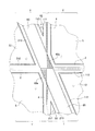
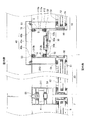
図1は、本発明の実施の形態であるカーテンウォール用パネルユニットを示したものである。ここで例示するパネルユニット1は、図2に示すように、従前のパネルユニット1′に混在させた状態で上下左右に複数並設し、それぞれを柱、梁、床等の構造体Bに支持させることにより、ビル等の建築物にカーテンウォールを構成するものである。従前のパネルユニット1′は、上枠材2、下枠材3及び左右の縦枠材4を四周枠組みすることによって構成した枠体の内部に面材5を支持させたものである。これに対して本発明の実施の形態となるパネルユニット1は、図1の(b)に示すように、上部枠構成要素10及び下部枠構成要素20と、これら2つの枠構成要素10,20を連結する外方連結パネル(連結部材)30及び内方連結パネル(連結部材)40とを備えている。
FIG. 1 shows a curtain wall panel unit according to an embodiment of the present invention. As shown in FIG. 2, the
上部枠構成要素10及び下部枠構成要素20は、それぞれ枠11,21の内部に面材12,22を支持したもので、互いにほぼ同じ大きさとなるように構成してある。上部枠構成要素10の枠11は、上部縦枠材111、上部横枠材112及び上部傾斜骨材113によって三角形状の外形を有するものである。上部縦枠材111及び上部横枠材112は、互いにほぼ直角に交わるように接合してあり、上部傾斜骨材113は、上部縦枠材111及び上部横枠材112の端部間を連結するように接合してある。上部縦枠材111、上部横枠材112、上部傾斜骨材113は、図4〜図6に示すように、いずれもアルミニウム合金によって成形した中空部を有する押し出し形材であり、全長にわたってほぼ一様な断面形状を有するように構成してある。また、上部縦枠材111において上部傾斜骨材113よりも突出する部分には、上部連結ブロック(連結部材)111aが設けてある。図には明示していないが、上部連結ブロック111aは、後述の下部枠構成要素20を構成する下部横枠材212の中空部に挿入することのできる寸法に形成してある。また、図には明示していないが、上部縦枠材111からの上部連結ブロック111aの突出方向は、枠11に対して室内側に角度αだけ傾斜するように設定してある。
The
下部枠構成要素20の枠21は、図1に示すように、下部縦枠材211、下部横枠材212及び下部傾斜骨材213によって三角形状の外形を有するものである。下部縦枠材211及び下部横枠材212は、互いにほぼ直角に交わるように接合してあり、下部傾斜骨材213は、下部縦枠材211及び下部横枠材212の端部間を連結するように接合してある。下部縦枠材211、下部横枠材212、下部傾斜骨材213は、図4〜図6に示すように、いずれもアルミニウム合金によって成形した中空部を有する押し出し形材であり、全長にわたってほぼ一様な断面形状を有するように構成してある。また、下部縦枠材211において上部傾斜骨材113よりも突出する部分には、下部連結ブロック(連結部材)211aが設けてある。下部連結ブロック211aは、上述した上部横枠材112の中空部に挿入することのできる寸法に形成してある。また、図には明示していないが、下部縦枠材211からの下部連結ブロック211aの突出方向は、枠21に対して室内側に角度αだけ傾斜するように設定してある。
As shown in FIG. 1, the
上述の構成を有する上部枠構成要素10及び下部枠構成要素20においては、図1の(a)からも明らかなように、上部縦枠材111と下部縦枠材211とが互いに平行となり、かつ上部横枠材112と下部横枠材212とが互いに平行となる姿勢で上部傾斜骨材113と下部傾斜骨材213とを互いに対向配置した場合、上部縦枠材111及び上部横枠材112と、下部縦枠材211及び下部横枠材212とによって長方形が構成されることになる。この状態から、上部枠構成要素10の上部連結ブロック111aを下部横枠材212の内空部に挿入し、かつ下部枠構成要素20の下部連結ブロック211aを上部横枠材112の中空部に挿入すると、上部枠構成要素10と下部枠構成要素20とを互いにほぼαの角度だけ傾斜した状態に配置することができる。
In the
図2に示すように、本実施の形態では、それぞれの縦枠材111,211としてビルのフロア1階分とほぼ等しい高さ寸法を有したものを適用し、かつ横枠材112,212として縦枠材111,211のほぼ2/5の長さを有したものを適用している。上部傾斜骨材113及び下部傾斜骨材213が互いに対向した状態で横枠材112,212が水平となるように上部枠構成要素10及び下部枠構成要素20を配置した場合には、それぞれの縦枠材111,211及び横枠材112,212によって縦長の長方形が構成されることになる。
As shown in FIG. 2, in the present embodiment, the
また、上部枠構成要素10には上部無目枠材114が設けてあり、下部枠構成要素20には下部無目枠材214が設けてある。それぞれの無目枠材114,214は、横枠材112,212と平行となるように延在するもので、縦枠材111,211と傾斜骨材113,213との間に掛け渡すように配設してある。上部枠構成要素10に設けた上部無目枠材114は、上部横枠材112との距離が、上部縦枠材111のほぼ1/5の長さとなる位置に設けてある。下部枠構成要素20に設けた下部無目枠材214は、下部横枠材212との距離が、下部縦枠材211のほぼ1/5の長さとなる位置に設けてある。つまり、上部傾斜骨材113及び下部傾斜骨材213を互いに対向配置した場合に、上部枠構成要素10に設けた上部無目枠材114と、下部枠構成要素20に設けた下部無目枠材214とが同一の直線上に配置されるように構成してある。上部無目枠材114及び下部無目枠材214は、上部縦枠材111等と同様、アルミニウム合金によって成形した押し出し形材であり、全長にわたってほぼ一様な断面形状を有するように構成してある。
The
図4〜図6に示すように、上部枠構成要素10の枠11及び下部枠構成要素20の枠21において、それぞれ無目枠材114,214よりも上方となる部位には面材12,22として単層ガラスが配設してあり、無目枠材114,214よりも下方となる部位には面材12,22として複層ガラスが配設してある。それぞれの面材12,22は、枠11,21の室外に臨む見付け面と押縁50との間に挟持されたものである。面材12,22の外表面と押縁50との間、並びに面材12,22の内表面と枠11,21との間には、それぞれ所望の水密性及び気密性を確保するためのシール材51が設けてある。
As shown in FIG. 4 to FIG. 6, in the
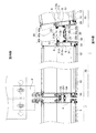
図5及び図6に示すように、上部傾斜骨材113の外周側となる見込み面及び下部傾斜骨材213の外周側となる見込み面には、それぞれ外方連結ヒレ部113a,213a及び内方連結ヒレ部113b,213bが設けてある。外方連結ヒレ部113a,213a及び内方連結ヒレ部113b,213bは、それぞれ傾斜骨材113,213の長手方向に沿って延在する平板状部分であり、互いに平行となる状態で見込み方向に並設してある。図5及び図6からも明らかなように、本実施の形態では、上部傾斜骨材113の外周側となる見込み面及び下部傾斜骨材213の外周側となる見込み面がそれぞれ平面状となっており、外方連結ヒレ部113a,213a及び内方連結ヒレ部113b,213bが個々の見込み面から直交する方向に沿って突設してある。
As shown in FIGS. 5 and 6, the prospective surface on the outer peripheral side of the upper
パネルユニット1の外方連結パネル30は、それぞれの傾斜骨材113,213に設けた外方連結ヒレ部113a,213aを互いに連結するためのものであり、内方連結パネル40は、それぞれの傾斜骨材113,213に設けた内方連結ヒレ部113b,213bを互いに連結するためのものである。それぞれの連結パネル30,40は、図1の(b)に示すように、傾斜骨材113,213とほぼ同じ長さを有した基板部30a,40aと、基板部30a,40aの両側に設けた接合ヒレ部30b,40bとを一体に成形したものである。図3、図5及び図6に示すように、外方連結パネル30の接合ヒレ部30bは、傾斜骨材113,213の外方連結ヒレ部113a,213aに対して室外に臨む見付け面に当接する部分である。内方連結パネル40の接合ヒレ部40bは、傾斜骨材113,213の内方連結ヒレ部113b,213bに対して室内に臨む見付け面に当接する部分である。
The
外方連結パネル30に設けた一対の接合ヒレ部30bは、それぞれ外方連結ヒレ部113a,213aとの当接面が互いに傾斜するように構成してある。同様に、内方連結パネル40に設けた一対の接合ヒレ部40bは、それぞれ内方連結ヒレ部113b,213bとの当接面が互いに傾斜するように構成してある。より具体的に説明すると、接合ヒレ部30bの当接面は、基板部30aの長手方向に沿った中心線を含み、かつ基板部30aに直交する仮想平面P1上において相互に交差するように傾斜して設けてある。同様に、接合ヒレ部40bの当接面は、基板部40aの長手方向に沿った中心線を含み、かつ基板部40aに直交する仮想平面P2上において相互に交差するように傾斜して設けてある。本実施の形態では、特に、接合ヒレ部30b,40bの当接面が基板部30a,40aよりも室外側において相互に交差するように外方連結パネル30及び内方連結パネル40が構成してある。外方連結パネル30において接合ヒレ部30bの当接面が互いに傾斜する傾斜角度αは、上述した枠11,21に対する連結ブロック111a,211aの傾斜角度αと同一であり、かつ内方連結パネル40において接合ヒレ部40bの当接面が互いに傾斜する傾斜角度αとも同一である。
The pair of joining
上記のように構成した外方連結パネル30及び内方連結パネル40は、接合ヒレ部30b,40bを内方連結ヒレ部113b,213b及び外方連結ヒレ部113a,213aに当接した状態で適宜箇所に連結ネジSを螺合することにより、上部傾斜骨材113及び下部傾斜骨材213を介して上部枠構成要素10と下部枠構成要素20とを互いに連結した状態に維持する。外方連結パネル30と外方連結ヒレ部113a,213aとの接合部には、室外側からシール材52を充填することで水密性及び気密性が確保してある。同様に、内方連結パネル40と内方連結ヒレ部113b,213bとの接合部には、室内側からシール材53を充填することで水密性及び気密性が確保してある。このとき、図には明示していないが、下部横枠材212とその中空部に挿入された上部連結ブロック111aとの間にネジを螺合するとともに、上部横枠材112とその中空部に挿入された下部連結ブロック211aとの間にネジを螺合すれば、上部枠構成要素10と下部枠構成要素20との間をより強固に固定された状態となる。
The
このように連結パネル30,40によって傾斜骨材113,213の間を連結し、かつ連結ブロック111a,211aによって横枠材112,212と縦枠材211,111との間を連結した2つの枠構成要素10,20は、上部横枠材112、上部縦枠材111、下部縦枠材211及び下部横枠材212によってほぼ矩形状の枠体を構成し、かつこの矩形状の枠体の左上から右下に向けて斜材が延在した一体のパネルユニット1となる。従って、図2に示すように、従前のパネルユニット1′と同様、ファスナーFを介して上部縦枠材111及び下部縦枠材211をそれぞれ構造体Bに支持させれば、カーテンウォールを構成することができる。パネルユニット1とパネルユニット1′との間においては、図4〜図6に示すように、一次止水材54及び二次止水材55を互いに圧接させることで所望の水密性及び気密性を確保するようにしている。
In this way, two frames in which the
パネルユニット1の上部横枠材112と上方に配置されたパネルユニット1′との間においては、上部横枠材112に設けた係合ヒレ部112aを下枠材3に設けた係合溝3aに係合させることによって下枠材3の室外側への移動を規制することができる。同様に、パネルユニット1の下部横枠材212と下方に配置されたパネルユニット1′との間においては、図には明示していないが、下部横枠材212に設けた係合凹部に上枠材2に設けた係合ヒレ部に係合させることによって下部横枠材212の室外側への移動を規制することができる。
Between the upper
ここで、互いに連結した上部枠構成要素10及び下部枠構成要素20は、連結ブロック111a,211aの傾斜角度α及び連結パネル30,40に設けた一対の接合ヒレ部30b,40bの傾斜角度α従って互いに傾斜した状態となる。すなわち、上述のパネルユニット1においては、ほぼ矩形状を成す枠11,21の左上から右下に向けて延在する斜材を境界として上部枠構成要素10及び下部枠構成要素20が互いに異なる平面上に位置することになる。従って、図2に示すように、この斜材が連続するように複数のパネルユニット1を構造体Bに支持させれば、斜材を境界として2つの平面が交わるようにカーテンウォールを構成することが可能となり、カーテンウォールを多面化することで、建築物の意匠性をより向上させることができる。
Here, the
上述したように、上部枠構成要素10及び下部枠構成要素20を備えたパネルユニット1は、従前のパネルユニット1′と同様に外形がほぼ矩形状を成す一体のものであり、構造体Bへの支持構造も従前と同様のものを適用することができる。従って、カーテンウォールを構成する場合に取り扱い部品点数が増えることはなく、工期が長くなるおそれもない。また、パネルユニット1のいずれの隅部においても、その周囲には3枚のパネルユニット1,1′が配置されるのみであり、ファスナーFを設ける位置や一次止水材54、二次止水材55を引き回す位置を確保することも容易となる。
As described above, the
さらに、室外側においては、図5及び図6に示すように、外方連結パネル30の室外に臨む見付け面全長を覆うように外装カバー部材60を外方連結パネル30に取り付ければ、カーテンウォールを室外側から見た場合の外観品質を向上させることができる。特に、本実施の形態では、図2、図7、図8に示すように、外装カバー部材60の端部を縦枠材111,211よりも側方に突出し、かつ端面を水平方向に沿うように突出部分60aを形成しているため、上方のパネルユニット1と下方のパネルユニット1との間において外装カバー部材60が連続した印象を与えることができ、意匠性を考慮した場合、好ましいものとなる。
Further, on the outdoor side, as shown in FIGS. 5 and 6, if the
同様に、室内側においても、図6に示すように、無目枠材114,214よりも下方に位置する上部傾斜骨材113の見付け面から下部傾斜骨材213の見付け面までの間を内装カバー部材70によって覆うようにすれば、室内側から見た場合に、傾斜骨材113,213や、内方連結パネル40、シール材53が外部に露出したり、視認されるおそれもなく、外観品質が損なわれる事態を未然に防止することができる。
Similarly, on the indoor side, as shown in FIG. 6, the interior from the finding surface of the upper
尚、上述した実施の形態では、上部枠構成要素10及び下部枠構成要素20を互いに傾斜した状態で外方連結パネル30及び内方連結パネル40によって連結するようにしているが、必ずしもこれに限定されない。すなわち、図9の変形例に示すように、接合ヒレ部30b,40bが同一の平面上に位置する外方連結パネル30及び内方連結パネル40によって上部枠構成要素10と下部枠構成要素20とを互いに連結することにより、平板状のパネルユニット1を構成するようにしても良いし、その他の傾斜角度で上部枠構成要素10と下部枠構成要素20とを連結するようにしても構わない。この場合、連結ブロック111a,211aの突出方向についても接合ヒレ部30b,40bに応じて適宜変更する必要があるのはいうまでもない。また、上部枠構成要素10及び下部枠構成要素20を傾斜させる場合に上述した実施の形態では外方に向けて凸となるようにパネルユニット1を構成しているが、室内側に向けて凸となるようにパネルユニット1を傾斜させるようにしても良い。尚、図9の変形例において実施の形態と同様の構成については、同一の符号が付してある。
In the above-described embodiment, the
また、上述した実施の形態では、上部枠構成要素10及び下部枠構成要素20がほぼ同じ大きさを有するように構成してあるが、必ずしも上部枠構成要素10と下部枠構成要素20とが同じ大きさである必要はない。さらに、上部枠構成要素10及び下部枠構成要素20が三角形状の外形を有している必要はなく、台形状の外形を有するように枠構成要素10,20を構成することも可能である。この場合、例えば上部枠構成要素10が台形状の外形を有し、かつ下部枠構成要素20が三角形状の外形を有する等、両者が同じ外形を有している必要もない。また、それぞれの枠構成要素10,20において縦枠材111,211と横枠材112,212とが直角に交わるように接合しているが、縦枠材111,211と横枠材112,212とが直角に交わる必要はない。さらに、矩形状を成す枠体の左上から右下に斜材が延在するようにパネルユニットを構成しているが、斜材の向きは右上から左下に延在するようにしてももちろん良い。尚、枠構成要素10,20の面材12,22として単層ガラス及び複層ガラスを適用したものを例示しているが、その他の面材を適用しても構わない。
In the embodiment described above, the
さらに、上述した実施の形態では、連結部材として縦枠材111,211と横枠材212,112との間を連結する連結ブロック111a,211aと、傾斜骨材113,213の相互間を連結する連結パネル30,40を適用しているが、いずれか一方の連結部材を用いれば十分である。また、連結パネル30の室外に臨む見付け面を外装カバー部材60によって覆い、かつ上部傾斜骨材113及び下部傾斜骨材213の室内に臨む見付け面を内装カバー部材70によって覆うようにしているが、外装カバー部材60及び内装カバー部材70は設けなくても良い。
Further, in the embodiment described above, the connecting
1 パネルユニット、10 上部枠構成要素、12,22 面材、20 下部枠構成要素、30,40 連結パネル、60 外装カバー部材、70 内装カバー部材、111 上部縦枠材、111a 上部連結ブロック、112 上部横枠材、113 上部傾斜骨材、211 下部縦枠材、211a 下部連結ブロック、212 下部横枠材、213 下部傾斜骨材
DESCRIPTION OF
Claims (5)
互いに端部を介して相互に連結した下部縦枠材及び下部横枠材を備えるとともに、前記下部縦枠材及び前記下部横枠材の双方に対して傾斜する方向に延在する下部傾斜骨材を備え、前記下部縦枠材、前記下部横枠材及び前記下部傾斜骨材の間に面材を支持することによって構成した下部枠構成要素と、
前記上部枠構成要素及び前記下部枠構成要素の間を連結する連結部材と
を備えたことを特徴とするカーテンウォール用パネルユニット。 An upper inclined aggregate that includes an upper vertical frame member and an upper horizontal frame member that are connected to each other through end portions, and that extends in a direction inclined with respect to both the upper vertical frame member and the upper horizontal frame member. An upper frame component configured by supporting a face material between the upper vertical frame material, the upper horizontal frame material, and the upper inclined aggregate, and
A lower inclined aggregate that includes a lower vertical frame member and a lower horizontal frame member that are connected to each other via end portions, and that extends in a direction inclined with respect to both the lower vertical frame member and the lower horizontal frame member. A lower frame component configured by supporting a face material between the lower vertical frame material, the lower horizontal frame material, and the lower inclined aggregate, and
A curtain wall panel unit comprising: a connecting member that connects the upper frame component and the lower frame component.
Priority Applications (1)
| Application Number | Priority Date | Filing Date | Title |
|---|---|---|---|
| JP2015067309A JP6431423B2 (en) | 2015-03-27 | 2015-03-27 | Curtain wall panel unit and building |
Applications Claiming Priority (1)
| Application Number | Priority Date | Filing Date | Title |
|---|---|---|---|
| JP2015067309A JP6431423B2 (en) | 2015-03-27 | 2015-03-27 | Curtain wall panel unit and building |
Publications (2)
| Publication Number | Publication Date |
|---|---|
| JP2016186201A JP2016186201A (en) | 2016-10-27 |
| JP6431423B2 true JP6431423B2 (en) | 2018-11-28 |
Family
ID=57203141
Family Applications (1)
| Application Number | Title | Priority Date | Filing Date |
|---|---|---|---|
| JP2015067309A Active JP6431423B2 (en) | 2015-03-27 | 2015-03-27 | Curtain wall panel unit and building |
Country Status (1)
| Country | Link |
|---|---|
| JP (1) | JP6431423B2 (en) |
Families Citing this family (3)
| Publication number | Priority date | Publication date | Assignee | Title |
|---|---|---|---|---|
| JP7063673B2 (en) * | 2018-03-29 | 2022-05-17 | 株式会社Lixil | Joint width adjustment mechanism of continuous window structure and joint width adjustment method |
| CN113585559B (en) * | 2021-07-06 | 2023-03-14 | 深圳市大地幕墙科技有限公司 | Curtain wall unit and curtain wall with same |
| CN120776799B (en) * | 2025-09-04 | 2026-01-06 | 湖北省工业建筑集团有限公司 | A boomerang-shaped installation structure and installation method for curtain walls |
Family Cites Families (5)
| Publication number | Priority date | Publication date | Assignee | Title |
|---|---|---|---|---|
| JPS58114320U (en) * | 1982-01-29 | 1983-08-04 | 日本軽金属株式会社 | Decorative cover mounting device between frame materials |
| JPS5924829U (en) * | 1982-08-09 | 1984-02-16 | ワイケイケイ株式会社 | Insulating material for curtain wall |
| JP2759602B2 (en) * | 1993-10-25 | 1998-05-28 | 住友軽金属工業株式会社 | Construction with metal honeycomb panels |
| JP4527093B2 (en) * | 2006-09-19 | 2010-08-18 | Ykk Ap株式会社 | Corner member and panel unit |
| BE1018045A5 (en) * | 2008-03-12 | 2010-04-06 | Bvba Claerhout Van Biervliet | DEFORMABLE SLATCH SYSTEM. |
-
2015
- 2015-03-27 JP JP2015067309A patent/JP6431423B2/en active Active
Also Published As
| Publication number | Publication date |
|---|---|
| JP2016186201A (en) | 2016-10-27 |
Similar Documents
| Publication | Publication Date | Title |
|---|---|---|
| CN101208486B (en) | Protruding corner structures and interior concave wall structures of buildings | |
| JP6431423B2 (en) | Curtain wall panel unit and building | |
| KR101091953B1 (en) | Curtain wall structure | |
| JP5041533B2 (en) | Display case | |
| KR101520878B1 (en) | Framed structure of temporary building using light weight frame member and fastening bolt | |
| KR101429021B1 (en) | Partitioning panel | |
| JP2018066154A (en) | Frame corner structure | |
| JP6087642B2 (en) | Building exterior panel | |
| JP4991513B2 (en) | fence | |
| JP6452301B2 (en) | Construction panels and panel bodies | |
| JP2014190141A (en) | Panel unit and curtain wall | |
| JP7328107B2 (en) | curtain wall and building | |
| JP6894822B2 (en) | Panel structure | |
| JP2019044557A (en) | Unit curtain wall | |
| JP7146569B2 (en) | curtain wall | |
| JP6993304B2 (en) | Joinery | |
| JP6723809B2 (en) | Building insulation structure | |
| JP2021161751A (en) | Sash frame, opening structure, and building | |
| JP7377748B2 (en) | building exterior wall structure | |
| KR101223472B1 (en) | Bracket for fixing glass panel | |
| JP5913530B2 (en) | Building structure | |
| JP6867810B2 (en) | Structure | |
| JP2009185500A (en) | Rod connecting structure in curtain wall | |
| JP6235802B2 (en) | Insulated lighting fixtures | |
| JP2024120242A (en) | Outdoor Structure |
Legal Events
| Date | Code | Title | Description |
|---|---|---|---|
| A621 | Written request for application examination |
Free format text: JAPANESE INTERMEDIATE CODE: A621 Effective date: 20171213 |
|
| A977 | Report on retrieval |
Free format text: JAPANESE INTERMEDIATE CODE: A971007 Effective date: 20181012 |
|
| TRDD | Decision of grant or rejection written | ||
| A01 | Written decision to grant a patent or to grant a registration (utility model) |
Free format text: JAPANESE INTERMEDIATE CODE: A01 Effective date: 20181023 |
|
| A61 | First payment of annual fees (during grant procedure) |
Free format text: JAPANESE INTERMEDIATE CODE: A61 Effective date: 20181102 |
|
| R150 | Certificate of patent or registration of utility model |
Ref document number: 6431423 Country of ref document: JP Free format text: JAPANESE INTERMEDIATE CODE: R150 |
|
| R250 | Receipt of annual fees |
Free format text: JAPANESE INTERMEDIATE CODE: R250 |
|
| R250 | Receipt of annual fees |
Free format text: JAPANESE INTERMEDIATE CODE: R250 |