JP6476109B2 - 分岐コネクタ - Google Patents
分岐コネクタ Download PDFInfo
- Publication number
- JP6476109B2 JP6476109B2 JP2015253394A JP2015253394A JP6476109B2 JP 6476109 B2 JP6476109 B2 JP 6476109B2 JP 2015253394 A JP2015253394 A JP 2015253394A JP 2015253394 A JP2015253394 A JP 2015253394A JP 6476109 B2 JP6476109 B2 JP 6476109B2
- Authority
- JP
- Japan
- Prior art keywords
- cable
- pair
- holding portion
- cable holding
- housings
- Prior art date
- Legal status (The legal status is an assumption and is not a legal conclusion. Google has not performed a legal analysis and makes no representation as to the accuracy of the status listed.)
- Active
Links
Images



Classifications
-
- H—ELECTRICITY
- H01—ELECTRIC ELEMENTS
- H01R—ELECTRICALLY-CONDUCTIVE CONNECTIONS; STRUCTURAL ASSOCIATIONS OF A PLURALITY OF MUTUALLY-INSULATED ELECTRICAL CONNECTING ELEMENTS; COUPLING DEVICES; CURRENT COLLECTORS
- H01R13/00—Details of coupling devices of the kinds covered by groups H01R12/70 or H01R24/00 - H01R33/00
- H01R13/58—Means for relieving strain on wire connection, e.g. cord grip, for avoiding loosening of connections between wires and terminals within a coupling device terminating a cable
-
- H—ELECTRICITY
- H01—ELECTRIC ELEMENTS
- H01R—ELECTRICALLY-CONDUCTIVE CONNECTIONS; STRUCTURAL ASSOCIATIONS OF A PLURALITY OF MUTUALLY-INSULATED ELECTRICAL CONNECTING ELEMENTS; COUPLING DEVICES; CURRENT COLLECTORS
- H01R4/00—Electrically-conductive connections between two or more conductive members in direct contact, i.e. touching one another; Means for effecting or maintaining such contact; Electrically-conductive connections having two or more spaced connecting locations for conductors and using contact members penetrating insulation
- H01R4/24—Connections using contact members penetrating or cutting insulation or cable strands
- H01R4/2416—Connections using contact members penetrating or cutting insulation or cable strands the contact members having insulation-cutting edges, e.g. of tuning fork type
- H01R4/242—Connections using contact members penetrating or cutting insulation or cable strands the contact members having insulation-cutting edges, e.g. of tuning fork type the contact members being plates having a single slot
- H01R4/2425—Flat plates, e.g. multi-layered flat plates
- H01R4/2429—Flat plates, e.g. multi-layered flat plates mounted in an insulating base
- H01R4/2433—Flat plates, e.g. multi-layered flat plates mounted in an insulating base one part of the base being movable to push the cable into the slot
-
- H—ELECTRICITY
- H01—ELECTRIC ELEMENTS
- H01R—ELECTRICALLY-CONDUCTIVE CONNECTIONS; STRUCTURAL ASSOCIATIONS OF A PLURALITY OF MUTUALLY-INSULATED ELECTRICAL CONNECTING ELEMENTS; COUPLING DEVICES; CURRENT COLLECTORS
- H01R13/00—Details of coupling devices of the kinds covered by groups H01R12/70 or H01R24/00 - H01R33/00
- H01R13/46—Bases; Cases
- H01R13/502—Bases; Cases composed of different pieces
- H01R13/506—Bases; Cases composed of different pieces assembled by snap action of the parts
-
- H—ELECTRICITY
- H01—ELECTRIC ELEMENTS
- H01R—ELECTRICALLY-CONDUCTIVE CONNECTIONS; STRUCTURAL ASSOCIATIONS OF A PLURALITY OF MUTUALLY-INSULATED ELECTRICAL CONNECTING ELEMENTS; COUPLING DEVICES; CURRENT COLLECTORS
- H01R31/00—Coupling parts supported only by co-operation with counterpart
- H01R31/02—Intermediate parts for distributing energy to two or more circuits in parallel, e.g. splitter
Landscapes
- Details Of Connecting Devices For Male And Female Coupling (AREA)
- Connections By Means Of Piercing Elements, Nuts, Or Screws (AREA)
- Cable Accessories (AREA)
Description
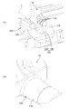
本発明の分岐コネクタは、互いに開閉可能な一対の分割ハウジングと、前記一対の分割ハウジングに支持され、前記一対の分割ハウジングの閉状態において、前記一対の分割ハウジングに導かれるケーブルと電気的に接続される中継コンタクトと、前記一対の分割ハウジングに形成された、前記ケーブルを保持するケーブル保持部と、を有し、前記ケーブル保持部は、前記一対の分割ハウジングの閉状態において、前記ケーブルをその径方向移動が相対的に小さくなるように保持する、前記中継コンタクトに近い側の緊ケーブル保持部と、前記ケーブルをその径方向移動が相対的に大きくなるように保持する、前記中継コンタクトから遠い側の緩ケーブル保持部とを有し、前記一対の分割ハウジングの少なくとも一方に形成された、前記ケーブルの径方向移動量を前記緩ケーブル保持部における前記ケーブルの径方向移動量よりも大きく弾性保持する、前記緩ケーブル保持部の先端側に位置する弾性保持部をさらに有する、ことを特徴としている。
10 第1分割ハウジング(一対の分割ハウジング)
10a 10b ロック片
11 外周側第1対向面
12 防水壁部
13 平坦部
14 中継コンタクト取付凹部
14A 固定ピン
20 第2分割ハウジング(一対の分割ハウジング)
20a ロック孔
20b ロック部
20c ロック孔
20d ロック部
21 外周側第2対向面
22 収容壁部
23 ケーブル押圧突起
23A ケーブル押圧溝
30 接続部
32 折曲部
40 中継コンタクト
41 底壁
42 ケーブル圧接壁
42A ケーブル圧接用溝
43 延出壁
44 ケーブル圧着部
44A ケーブル圧着片
50 第1ケーブル
52 芯線
54 被覆
60 第2ケーブル
62 芯線
64 被覆
100 前方ケーブル保持部(ケーブル保持部)
105 半円筒支持部
110 U字状溝(緊ケーブル保持部)
115 傾斜面(緩ケーブル保持部)
120 ケーブル保持溝(緩ケーブル保持部)
125 U字状溝(緩ケーブル保持部)
130 傾斜接続溝(緩ケーブル保持部)
150 後方ケーブル保持部
155 U字状溝
200 前方ケーブル保持部(ケーブル保持部)
205 半円筒支持部
210 U字状溝(緊ケーブル保持部)
215 傾斜面(緩ケーブル保持部)
220 ケーブル保持溝(緩ケーブル保持部)
225 弾性保持部
230 保持アーム
235 ケーブル載置部
240 弾性抜止突起
250 後方ケーブル保持部
255 U字状溝
Claims (7)
- 互いに開閉可能な一対の分割ハウジングと、
前記一対の分割ハウジングに支持され、前記一対の分割ハウジングの閉状態において、前記一対の分割ハウジングに導かれるケーブルと電気的に接続される中継コンタクトと、
前記一対の分割ハウジングに形成された、前記ケーブルを保持するケーブル保持部と、
を有し、
前記ケーブル保持部は、前記一対の分割ハウジングの閉状態において、前記ケーブルをその径方向移動が相対的に小さくなるように保持する、前記中継コンタクトに近い側の緊ケーブル保持部と、前記ケーブルをその径方向移動が相対的に大きくなるように保持する、前記中継コンタクトから遠い側の緩ケーブル保持部とを有し、
前記緩ケーブル保持部は、
前記一対の分割ハウジングに形成された、前記一対の分割ハウジングの開閉方向と前記ケーブルの延在方向の双方に対して傾斜するとともに前記一対の分割ハウジングの閉状態で対向する一対の傾斜面と、
前記一対の傾斜面が対向したときに前記ケーブルを協働保持する一対のケーブル保持溝と、を有し、
前記一対のケーブル保持溝の少なくとも一方は、前記ケーブルの径より深さが浅いU字状溝と、前記U字状溝の周縁部からその径を広げながら前記傾斜面に接続される傾斜接続溝とを有する、
ことを特徴とする分岐コネクタ。 - 互いに開閉可能な一対の分割ハウジングと、
前記一対の分割ハウジングに支持され、前記一対の分割ハウジングの閉状態において、前記一対の分割ハウジングに導かれるケーブルと電気的に接続される中継コンタクトと、
前記一対の分割ハウジングに形成された、前記ケーブルを保持するケーブル保持部と、
を有し、
前記ケーブル保持部は、前記一対の分割ハウジングの閉状態において、前記ケーブルをその径方向移動が相対的に小さくなるように保持する、前記中継コンタクトに近い側の緊ケーブル保持部と、前記ケーブルをその径方向移動が相対的に大きくなるように保持する、前記中継コンタクトから遠い側の緩ケーブル保持部とを有し、
前記一対の分割ハウジングの少なくとも一方に形成された、前記ケーブルの径方向移動量を前記緩ケーブル保持部における前記ケーブルの径方向移動量よりも大きく弾性保持する、前記緩ケーブル保持部の先端側に位置する弾性保持部をさらに有する、
ことを特徴とする分岐コネクタ。 - 請求項2記載の分岐コネクタにおいて、
前記緩ケーブル保持部は、前記一対の分割ハウジングに形成された、前記一対の分割ハウジングの開閉方向と前記ケーブルの延在方向の双方に対して傾斜するとともに前記一対の分割ハウジングの閉状態で対向する一対の傾斜面を有する、分岐コネクタ。 - 請求項3記載の分岐コネクタにおいて、
前記緩ケーブル保持部は、前記一対の傾斜面が対向したときに前記ケーブルを協働保持する一対のケーブル保持溝を有する、分岐コネクタ。 - 請求項4記載の分岐コネクタにおいて、
前記一対のケーブル保持溝の少なくとも一方は、前記ケーブルの径より深さが浅いU字状溝と、前記U字状溝の周縁部からその径を広げながら前記傾斜面に接続される傾斜接続溝とを有する、分岐コネクタ。 - 請求項1ないし5のいずれか1項記載の分岐コネクタにおいて、
前記緊ケーブル保持部は、前記一対の分割ハウジングの各々に形成された、前記ケーブルの延在方向に離間する複数のU字状溝を有する、分岐コネクタ。 - 請求項6記載の分岐コネクタにおいて、
一方の分割ハウジングに形成された複数のU字状溝は、前記ケーブルの径より深さが深く、他方の分割ハウジングに形成された複数のU字状溝は、前記ケーブルの径より深さが浅い、分岐コネクタ。
Priority Applications (5)
| Application Number | Priority Date | Filing Date | Title |
|---|---|---|---|
| JP2015253394A JP6476109B2 (ja) | 2015-12-25 | 2015-12-25 | 分岐コネクタ |
| CN201680076053.9A CN108432059B (zh) | 2015-12-25 | 2016-12-20 | 分支连接器 |
| US16/064,431 US10530092B2 (en) | 2015-12-25 | 2016-12-20 | Branch connector |
| PCT/JP2016/087974 WO2017110820A1 (ja) | 2015-12-25 | 2016-12-20 | 分岐コネクタ |
| EP16878709.1A EP3407435B1 (en) | 2015-12-25 | 2016-12-20 | Branch connector |
Applications Claiming Priority (1)
| Application Number | Priority Date | Filing Date | Title |
|---|---|---|---|
| JP2015253394A JP6476109B2 (ja) | 2015-12-25 | 2015-12-25 | 分岐コネクタ |
Publications (2)
| Publication Number | Publication Date |
|---|---|
| JP2017117703A JP2017117703A (ja) | 2017-06-29 |
| JP6476109B2 true JP6476109B2 (ja) | 2019-02-27 |
Family
ID=59090380
Family Applications (1)
| Application Number | Title | Priority Date | Filing Date |
|---|---|---|---|
| JP2015253394A Active JP6476109B2 (ja) | 2015-12-25 | 2015-12-25 | 分岐コネクタ |
Country Status (5)
| Country | Link |
|---|---|
| US (1) | US10530092B2 (ja) |
| EP (1) | EP3407435B1 (ja) |
| JP (1) | JP6476109B2 (ja) |
| CN (1) | CN108432059B (ja) |
| WO (1) | WO2017110820A1 (ja) |
Families Citing this family (6)
| Publication number | Priority date | Publication date | Assignee | Title |
|---|---|---|---|---|
| USD851600S1 (en) | 2017-01-13 | 2019-06-18 | Kyocera Corporation | Electric connector |
| JP6397962B1 (ja) * | 2017-05-24 | 2018-09-26 | 京セラ株式会社 | 梱包物 |
| JP1599349S (ja) * | 2017-08-04 | 2018-03-12 | ||
| JP1618016S (ja) * | 2018-02-05 | 2018-11-12 | ||
| US11545763B2 (en) * | 2020-02-10 | 2023-01-03 | KYOCERA AVX Components Corporation | Wire-to-wire connector with splice contact portion |
| KR102884798B1 (ko) * | 2022-12-14 | 2025-11-11 | 주식회사 한화 | 각선 잠금 구조를 가지는 뇌관용 커넥터 |
Family Cites Families (15)
| Publication number | Priority date | Publication date | Assignee | Title |
|---|---|---|---|---|
| US4326767A (en) * | 1979-03-12 | 1982-04-27 | Minnesota Mining And Manufacturing Company | Wire cutting electrical connector |
| JPS60170974U (ja) * | 1984-04-20 | 1985-11-13 | 住友電装株式会社 | クランプ |
| US4612423A (en) * | 1985-01-23 | 1986-09-16 | Eagle Electric Mfg. Co. Inc. | Line switch |
| JPS63171971U (ja) * | 1987-04-28 | 1988-11-09 | ||
| JP3028988B2 (ja) | 1992-02-05 | 2000-04-04 | トヨタ自動車株式会社 | コネクタ |
| JP2605275Y2 (ja) | 1993-12-27 | 2000-07-04 | 京セラエルコ株式会社 | 電気コネクタのケーブル保護装置 |
| FR2720551B1 (fr) * | 1994-05-25 | 1996-07-05 | Schneider Electric Sa | Connecteur autodénudant. |
| WO1999000873A1 (en) * | 1997-06-26 | 1999-01-07 | Expert Explosives (Pty.) Limited | Connector |
| US6837737B2 (en) * | 2002-10-10 | 2005-01-04 | American Standard International Inc. | Bus connector |
| JP4438590B2 (ja) * | 2004-10-13 | 2010-03-24 | 住友電装株式会社 | コネクタ |
| JP2008186670A (ja) | 2007-01-29 | 2008-08-14 | D D K Ltd | 電気コネクタ |
| DE102008057554B3 (de) * | 2008-11-15 | 2010-04-22 | Tyco Electronics Amp Gmbh | Elektrischer Steckverbinder mit Litzenführung |
| US8512066B2 (en) * | 2009-09-17 | 2013-08-20 | Jowoo-Tech Co. Ltd | Electric wire connector for press connecting electric wires |
| CN201667450U (zh) * | 2010-03-18 | 2010-12-08 | 欧姆龙(上海)有限公司 | 线缆紧固装置 |
| JP5787864B2 (ja) * | 2012-12-06 | 2015-09-30 | 京セラコネクタプロダクツ株式会社 | 分岐コネクタ |
-
2015
- 2015-12-25 JP JP2015253394A patent/JP6476109B2/ja active Active
-
2016
- 2016-12-20 EP EP16878709.1A patent/EP3407435B1/en active Active
- 2016-12-20 CN CN201680076053.9A patent/CN108432059B/zh active Active
- 2016-12-20 WO PCT/JP2016/087974 patent/WO2017110820A1/ja not_active Ceased
- 2016-12-20 US US16/064,431 patent/US10530092B2/en active Active
Also Published As
| Publication number | Publication date |
|---|---|
| EP3407435A1 (en) | 2018-11-28 |
| JP2017117703A (ja) | 2017-06-29 |
| US10530092B2 (en) | 2020-01-07 |
| EP3407435B1 (en) | 2021-05-19 |
| EP3407435A4 (en) | 2019-07-31 |
| CN108432059A (zh) | 2018-08-21 |
| US20190006790A1 (en) | 2019-01-03 |
| WO2017110820A1 (ja) | 2017-06-29 |
| CN108432059B (zh) | 2019-12-31 |
Similar Documents
| Publication | Publication Date | Title |
|---|---|---|
| JP6476109B2 (ja) | 分岐コネクタ | |
| JP5966041B1 (ja) | 分岐コネクタ | |
| JP6397965B1 (ja) | コネクタ | |
| JP6456510B2 (ja) | 分岐コネクタ | |
| JP6397864B2 (ja) | 分岐コネクタ | |
| JP2016189329A (ja) | 分岐コネクタ | |
| JP6486419B2 (ja) | コネクタ | |
| JP6495216B2 (ja) | 分岐コネクタ | |
| JP2013251114A (ja) | 圧接端子 | |
| CN109155486B (zh) | 分支连接器 | |
| KR102202562B1 (ko) | 커넥터 | |
| KR20190119629A (ko) | 커넥터 | |
| JP2014049200A (ja) | コネクタ及びワイヤハーネス | |
| JP5892384B2 (ja) | 雌端子 | |
| KR102216099B1 (ko) | 커넥터 | |
| CN110192310B (zh) | 连接器 | |
| JP6401770B2 (ja) | 分岐コネクタ | |
| WO2018173685A1 (ja) | コネクタ | |
| CN106997911A (zh) | 端子箱 | |
| JP2016033928A (ja) | コネクタ及びワイヤハーネス | |
| TWM486193U (zh) | 同軸連接器之結構改良 |
Legal Events
| Date | Code | Title | Description |
|---|---|---|---|
| A711 | Notification of change in applicant |
Free format text: JAPANESE INTERMEDIATE CODE: A712 Effective date: 20170524 |
|
| A621 | Written request for application examination |
Free format text: JAPANESE INTERMEDIATE CODE: A621 Effective date: 20170725 |
|
| A131 | Notification of reasons for refusal |
Free format text: JAPANESE INTERMEDIATE CODE: A131 Effective date: 20180626 |
|
| A521 | Written amendment |
Free format text: JAPANESE INTERMEDIATE CODE: A523 Effective date: 20180820 |
|
| TRDD | Decision of grant or rejection written | ||
| A01 | Written decision to grant a patent or to grant a registration (utility model) |
Free format text: JAPANESE INTERMEDIATE CODE: A01 Effective date: 20190129 |
|
| A61 | First payment of annual fees (during grant procedure) |
Free format text: JAPANESE INTERMEDIATE CODE: A61 Effective date: 20190204 |
|
| R150 | Certificate of patent or registration of utility model |
Ref document number: 6476109 Country of ref document: JP Free format text: JAPANESE INTERMEDIATE CODE: R150 |