JP6490708B2 - Medical fastening device and reference device, and medical device - Google Patents
Medical fastening device and reference device, and medical device Download PDFInfo
- Publication number
- JP6490708B2 JP6490708B2 JP2016559966A JP2016559966A JP6490708B2 JP 6490708 B2 JP6490708 B2 JP 6490708B2 JP 2016559966 A JP2016559966 A JP 2016559966A JP 2016559966 A JP2016559966 A JP 2016559966A JP 6490708 B2 JP6490708 B2 JP 6490708B2
- Authority
- JP
- Japan
- Prior art keywords
- support
- bandage
- marking
- region
- tightening device
- Prior art date
- Legal status (The legal status is an assumption and is not a legal conclusion. Google has not performed a legal analysis and makes no representation as to the accuracy of the status listed.)
- Active
Links
Images



Classifications
-
- A—HUMAN NECESSITIES
- A61—MEDICAL OR VETERINARY SCIENCE; HYGIENE
- A61B—DIAGNOSIS; SURGERY; IDENTIFICATION
- A61B34/00—Computer-aided surgery; Manipulators or robots specially adapted for use in surgery
- A61B34/20—Surgical navigation systems; Devices for tracking or guiding surgical instruments, e.g. for frameless stereotaxis
-
- A—HUMAN NECESSITIES
- A61—MEDICAL OR VETERINARY SCIENCE; HYGIENE
- A61B—DIAGNOSIS; SURGERY; IDENTIFICATION
- A61B17/00—Surgical instruments, devices or methods
- A61B17/12—Surgical instruments, devices or methods for ligaturing or otherwise compressing tubular parts of the body, e.g. blood vessels or umbilical cord
- A61B17/132—Tourniquets
- A61B17/1322—Tourniquets comprising a flexible encircling member
-
- A—HUMAN NECESSITIES
- A61—MEDICAL OR VETERINARY SCIENCE; HYGIENE
- A61B—DIAGNOSIS; SURGERY; IDENTIFICATION
- A61B90/00—Instruments, implements or accessories specially adapted for surgery or diagnosis and not covered by any of the groups A61B1/00 - A61B50/00, e.g. for luxation treatment or for protecting wound edges
- A61B90/39—Markers, e.g. radio-opaque or breast lesions markers
-
- D—TEXTILES; PAPER
- D04—BRAIDING; LACE-MAKING; KNITTING; TRIMMINGS; NON-WOVEN FABRICS
- D04B—KNITTING
- D04B1/00—Weft knitting processes for the production of fabrics or articles not dependent on the use of particular machines; Fabrics or articles defined by such processes
- D04B1/10—Patterned fabrics or articles
- D04B1/12—Patterned fabrics or articles characterised by thread material
-
- A—HUMAN NECESSITIES
- A61—MEDICAL OR VETERINARY SCIENCE; HYGIENE
- A61B—DIAGNOSIS; SURGERY; IDENTIFICATION
- A61B17/00—Surgical instruments, devices or methods
- A61B2017/00831—Material properties
- A61B2017/00858—Material properties high friction or non-slip
-
- A—HUMAN NECESSITIES
- A61—MEDICAL OR VETERINARY SCIENCE; HYGIENE
- A61B—DIAGNOSIS; SURGERY; IDENTIFICATION
- A61B34/00—Computer-aided surgery; Manipulators or robots specially adapted for use in surgery
- A61B34/20—Surgical navigation systems; Devices for tracking or guiding surgical instruments, e.g. for frameless stereotaxis
- A61B2034/2046—Tracking techniques
- A61B2034/2055—Optical tracking systems
-
- A—HUMAN NECESSITIES
- A61—MEDICAL OR VETERINARY SCIENCE; HYGIENE
- A61B—DIAGNOSIS; SURGERY; IDENTIFICATION
- A61B90/00—Instruments, implements or accessories specially adapted for surgery or diagnosis and not covered by any of the groups A61B1/00 - A61B50/00, e.g. for luxation treatment or for protecting wound edges
- A61B90/39—Markers, e.g. radio-opaque or breast lesions markers
- A61B2090/3983—Reference marker arrangements for use with image guided surgery
-
- A—HUMAN NECESSITIES
- A61—MEDICAL OR VETERINARY SCIENCE; HYGIENE
- A61B—DIAGNOSIS; SURGERY; IDENTIFICATION
- A61B90/00—Instruments, implements or accessories specially adapted for surgery or diagnosis and not covered by any of the groups A61B1/00 - A61B50/00, e.g. for luxation treatment or for protecting wound edges
- A61B90/39—Markers, e.g. radio-opaque or breast lesions markers
- A61B2090/3991—Markers, e.g. radio-opaque or breast lesions markers having specific anchoring means to fixate the marker to the tissue, e.g. hooks
-
- A—HUMAN NECESSITIES
- A61—MEDICAL OR VETERINARY SCIENCE; HYGIENE
- A61B—DIAGNOSIS; SURGERY; IDENTIFICATION
- A61B2576/00—Medical imaging apparatus involving image processing or analysis
-
- D—TEXTILES; PAPER
- D10—INDEXING SCHEME ASSOCIATED WITH SUBLASSES OF SECTION D, RELATING TO TEXTILES
- D10B—INDEXING SCHEME ASSOCIATED WITH SUBLASSES OF SECTION D, RELATING TO TEXTILES
- D10B2509/00—Medical; Hygiene
- D10B2509/02—Bandages, dressings or absorbent pads
- D10B2509/028—Elastic support stockings or elastic bandages
Landscapes
- Health & Medical Sciences (AREA)
- Surgery (AREA)
- Life Sciences & Earth Sciences (AREA)
- Engineering & Computer Science (AREA)
- Molecular Biology (AREA)
- Public Health (AREA)
- Veterinary Medicine (AREA)
- Biomedical Technology (AREA)
- Heart & Thoracic Surgery (AREA)
- Medical Informatics (AREA)
- Nuclear Medicine, Radiotherapy & Molecular Imaging (AREA)
- Animal Behavior & Ethology (AREA)
- General Health & Medical Sciences (AREA)
- Reproductive Health (AREA)
- Vascular Medicine (AREA)
- Oral & Maxillofacial Surgery (AREA)
- Pathology (AREA)
- Robotics (AREA)
- Textile Engineering (AREA)
- Prostheses (AREA)
- Surgical Instruments (AREA)
- Orthopedics, Nursing, And Contraception (AREA)
Description
本発明は患者の身体部分に、特に大腿に、2つ以上の標識要素を含む医療用標識装置を非侵襲的に緊締するための医療用緊締装置であって、表面上を互いに角度を成して整列する2つの広がり方向に延びると共に、標識装置が固定される又は固定可能である身体部分の輪郭に形状が適合可能である支持体を含む緊締装置に関する。 The present invention is a medical fastening device for non-invasively fastening a medical marking device comprising two or more marking elements to a patient's body part, in particular to the thigh, at an angle to each other on a surface. It relates to a clamping device comprising a support that extends in two spreading directions and is conformable to the contour of the body part to which the marking device is fixed or fixable.
本発明は、緊締装置及び標識装置を備えた医療用参照装置にも関する。 The invention also relates to a medical reference device comprising a tightening device and a marking device.
本発明は更に、医療機器に関する。 The invention further relates to a medical device.
医療用参照装置が知られている。医療用参照装置は、例えば膝プロテーゼにおいて、外科医が人工膝関節を移植することを容易にするために使用される。参照装置は、その空間移動がナビゲーションシステムにより追跡される互いに対して堅く配置された標識要素を備えた標識装置(いわゆる「剛体」)を含む。極力高い精度を達成するために、標識装置は、緊締装置、普通は骨ねじを用いて大腿骨に又は脛骨にねじ付けられ、これによって、大腿骨に又は脛骨にしっかりと固定される。ところが、このことにより外科医及び患者には不安の念を持つ者もある、少なからぬ程度の侵襲性による介入が起きる。 Medical reference devices are known. Medical reference devices are used, for example, in knee prostheses, to facilitate surgeons to implant a knee prosthesis. The reference device comprises a sign device (so-called “rigid body”) with sign elements arranged rigidly relative to each other whose spatial movement is tracked by the navigation system. In order to achieve the highest possible accuracy, the marking device is screwed to the femur or to the tibia using a tightening device, usually a bone screw, and thereby secured to the femur or to the tibia. However, this leads to some invasive interventions that some surgeons and patients are worried about.
侵襲性を低減するために、大腿部(この場合、大腿)又は脛部(この場合、下腿)の周りに置かれたスリーブ上に剛体を固定することが知られており又は大腿部上又は脛部上に置かれたプレート上に剛体を装着することが知られている。プレートはそれぞれの身体部分にバンドを用いて固定される。スリーブは、表面上を延びる支持体を備えた、冒頭で言及した種類の緊締装置を含む又は形成する。この支持体は、その本来は平面である形状から変形を受けることができ、身体部分へ確実嵌合できるように身体部分(例えば大腿部又は脛部)の輪郭に適合することができる。 To reduce invasiveness, it is known to fix a rigid body on a sleeve placed around the thigh (in this case, the thigh) or shin (in this case, the lower leg) or on the thigh Alternatively, it is known to mount a rigid body on a plate placed on the shin. The plate is fixed to each body part using a band. The sleeve comprises or forms a clamping device of the type mentioned at the beginning, with a support extending over the surface. The support can be deformed from its originally planar shape and can conform to the contour of the body part (eg thigh or shin) so that it can be securely fitted to the body part.
支持体も知られている。支持体は身体部分に接着接続することができ、支持体には標識装置が固定される。 Supports are also known. The support can be adhesively connected to the body part, and the marking device is fixed to the support.
このような非侵襲的緊締装置を用いると、特に身体部分の空間移動が検出されるべき際に、皮膚及び筋肉の移動、並びに軟組織変位が支持体を介して標識装置に伝達されるという問題が実際上生じる。これによって、ナビゲーション支援型の操作が依拠すべきである標識装置の‐故に身体部分の‐位置データの精度が損なわれる。 With such a non-invasive tightening device, there is a problem that the movement of the skin and muscles and the displacement of the soft tissue are transmitted to the labeling device via the support, especially when the spatial movement of the body part is to be detected. It actually occurs. This impairs the accuracy of the position data of the signage device—and thus the body part—on which navigation-assisted operation should be relied upon.
医療用ナビゲーションシステムを用いて、身体部分に非侵襲的に取付け可能な緊締装置を介して、術前及び術後に患者データを検出することも望ましいであろう。これによって外科的処置の時間を低減することができる。というのも、そのために必要なデータが術前に既に利用可能であり、術中に最初に測定される必要がないからである。手術の出来を術後に容易に監視することができる。いずれの場合も、それでなければ利用される電離撮像法、例えばX線又はCTに取って代えることができる。 It may also be desirable to detect patient data pre- and post-operatively using a medical navigation system via a clamping device that can be non-invasively attached to a body part. This can reduce the time of the surgical procedure. This is because the data required for this is already available before surgery and does not need to be measured first during surgery. The result of the operation can be easily monitored after the operation. In either case, ionization imaging methods that would otherwise be used, such as X-rays or CT, can be substituted.
本発明の目的は、それを使用して前記非侵襲的に得られる位置データがより高い精度を有する一般的な緊締装置、参照装置、及び機器を提供することである。 An object of the present invention is to provide a general tightening device, a reference device, and a device in which the position data obtained noninvasively using it has higher accuracy.
この目的は冒頭で言及した種類の緊締装置に関して、本発明によれば、前記支持体が、その広がりの表面において弾力的に伸縮可能であると共に、第1伸縮領域及び少なくとも1つの第2伸縮領域を含み、第2伸縮領域の前記支持体の広がりの表面における少なくとも1つの方向での伸縮可能性が、前記第1伸縮領域の伸縮可能性よりも小さいという点で成就される。 This object relates to a clamping device of the type mentioned at the outset, according to the invention, wherein the support is elastically stretchable on the surface of its extension, and a first stretch region and at least one second stretch region. The second stretchable region is achieved in that the stretchability in at least one direction on the surface of the spread of the support is smaller than the stretchability of the first stretchable region.
本発明による前記緊締装置の前記支持体は、弾力的に伸縮可能である。従って、この支持体を前記身体部分(例えば大腿部又は脛部)に張力下に緊締することができる。これによって、実際に分かるように、前記支持体の膨張下に前記皮膚、軟部、及び筋肉を圧縮することができる。このことにより、前記身体部分の互いに対する移動を低減することが可能になる。これによって、前記支持体上に故に前記標識装置上に前記身体部分により誘起される前記移動をも低減することができる。更に、前記支持体は第1及び少なくとも1つの第2伸縮領域を含む。第1及び少なくとも1つの第2伸縮領域は、前記支持体の広がりの表面における少なくとも1つの方向へのその伸縮可能性に関して相違する。伸縮可能性の異なる伸縮領域を提供することにより、前記皮膚、軟部、及び筋肉が異なる圧縮を受けることが可能である。これによって、実際に分かるように、これらの身体部分が前記支持体上で互いの間に移動を誘起することをかなり低減することができる。また、皮膚、筋肉、及び軟部の互いの間での移動を、実質、前記支持体内で吸収することができる。前記支持体の区域に前記標識装置が固定されることにより、得られた前記データの前記精度を増すことができる。このことを外科医は、それ自体低移動度を受けるものとして認識する。これによって、前記標識装置の前記骨、例えば大腿骨又は脛骨に関する安定した参照を達成することができる。以下で説明するように、外科医がこのための技術的補助を利用することが好ましい。 The support of the tightening device according to the present invention is elastically extendable. Accordingly, the support can be tightened to the body part (eg, thigh or shin) under tension. This allows the skin, soft parts and muscles to be compressed under the expansion of the support, as can be seen in practice. This makes it possible to reduce the movement of the body parts relative to each other. This can also reduce the movement induced by the body part on the support and hence on the marking device. Further, the support includes first and at least one second stretchable region. The first and at least one second stretch region differ with respect to their stretchability in at least one direction on the surface of the support spread. By providing stretchable regions with different stretchability, the skin, soft part, and muscle can be subjected to different compression. This makes it possible to considerably reduce that these body parts induce movement between each other on the support, as can be seen in practice. Also, the movement of skin, muscle and soft part between each other can be substantially absorbed within the support. By fixing the marking device in the area of the support, the accuracy of the obtained data can be increased. This is perceived by the surgeon as subject to low mobility. This makes it possible to achieve a stable reference for the bone of the marking device, for example the femur or tibia. As described below, it is preferred that the surgeon utilize technical assistance for this.
好ましくは、前記少なくとも1つの第2伸縮領域の前記支持体の広がりの表面において互いに対して角度を成して、特に交差方向にて整列する二方向での前記伸縮可能性は、前記第1伸縮領域の伸縮可能性よりも小さい。これによって、前記伸縮領域の前記伸縮可能性の差を増すことができる。これによって、実際に分かるように得られた前記位置データの前記精度を増すことができる。 Preferably, the stretchability of the at least one second stretchable region in the two directions aligned with each other at an angle relative to each other on the surface of the support spread, particularly in the cross direction, is the first stretchable Less than the stretchability of the area. Thereby, the difference in the stretchability of the stretchable region can be increased. Thus, the accuracy of the position data obtained as actually understood can be increased.
当然ながら、前記少なくとも1つの第2伸縮領域の前記支持体の広がりの表面における方向での前記伸縮可能性は、前記第1伸縮領域の前記伸縮可能性よりも小さいことを実現することができる。第1伸縮領域の方向は、最後に言及した前記緊締装置の前記有利な実施形態における前記二方向に対して角度を成して整列する。特に、第1伸縮領域の方向は、前記最後に言及した実施形態の前記二方向を重ね合わせたものである。 Naturally, it is possible to realize that the stretchability in the direction of the surface of the support of the at least one second stretchable region is smaller than the stretchability of the first stretchable region. The direction of the first telescopic region is aligned at an angle with respect to the two directions in the advantageous embodiment of the fastening device mentioned last. In particular, the direction of the first stretchable region is a superposition of the two directions of the last mentioned embodiment.
前記支持体の広がりの表面における、前記少なくとも1つの第2伸縮領域が前記第1伸縮領域よりも低い伸縮可能性を有する前記少なくとも1つの方向は、例えば、前記支持体の前記2つの広がり方向のうちの1つである。前記緊締装置が大腿又は脛部に適用され、このことにより前記支持体の変形が生じる際、前記第1広がり方向が、例えば大腿又は脛部の周方向に延びる。前記緊締装置が大腿又は脛部に適用される際、例えばその長手方向には、前記第1広がり方向に対して交差方向に整列する前記支持体の第2広がり方向が延びることができる。
The at least one direction in which the at least one second stretchable region has a lower stretchability than the first stretchable region on the surface of the support spread is, for example, the two spread directions of the support. One of them. When the tightening device is applied to the thigh or the shin part, and thereby the deformation of the support occurs, the first spreading direction extends, for example, in the circumferential direction of the thigh or shin part. When the tightening device is applied to the thigh or shin part, for example, in the longitudinal direction thereof, the second spreading direction of the support body aligned in the crossing direction with respect to the first spreading direction can extend.
本発明による前記緊締装置の有利な実施形態において、厳密に1つの第2伸縮領域が設けられる。それに応じて、前記支持体は第1伸縮領域及び第2伸縮領域を含むことができる。 In an advantageous embodiment of the tightening device according to the invention, exactly one second telescopic region is provided. Accordingly, the support may include a first stretch region and a second stretch region.
前記第1伸縮領域及び/又は前記少なくとも1つの第2伸縮領域が、自らの内部で連続していることが好都合であると分かる。 It can be seen that it is advantageous for the first stretch region and / or the at least one second stretch region to be continuous within itself.
前記緊締装置の異なる有利な実施形態において、前記第1伸縮領域及び/又は前記少なくとも1つの第2伸縮領域が空間的に互いと別々である区域を有することができることを実現することができる。 In different advantageous embodiments of the clamping device, it can be realized that the first stretchable region and / or the at least one second stretchable region can have sections that are spatially separated from one another.
前記緊締装置の実際に好都合な実施において、前記少なくとも1つの第2伸縮領域が前記第1伸縮領域を包囲することが有利である。例えば、前記少なくとも1つの第2伸縮領域は、前記支持体の表面において前記第1伸縮領域用の外被を形成する。前記少なくとも1つの第2伸縮領域は、特に前記支持体の縁部を形成することができる。この縁部は、前記第1伸縮領域を囲む。 In a practical expedient implementation of the clamping device, it is advantageous that the at least one second stretchable region surrounds the first stretchable region. For example, the at least one second stretchable region forms a jacket for the first stretchable region on the surface of the support. The at least one second stretchable region can in particular form an edge of the support. This edge surrounds the first stretchable region.
前記支持体は、平面視において、矩形の又は略矩形の輪郭を有することができる。例えば、このことは以下で説明するように、前記支持体が前記緊締装置により構成される包帯の区域又は構成要素である場合とすることができる。 The support may have a rectangular or substantially rectangular outline in plan view. For example, this may be the case when the support is an area or component of a bandage constituted by the clamping device, as will be explained below.
前記緊締装置の有利な実施において、前記第1伸縮領域が、前記支持体の表面の平面視において、矩形の又は略矩形の輪郭を有することが好都合であると分かる。このことは上で言及したように、特に前記少なくとも1つの第2伸縮領域が前記第1伸縮領域を囲んで前記支持体の縁部を形成する際に有利である。 In an advantageous implementation of the tightening device, it can be seen that it is advantageous for the first telescopic region to have a rectangular or substantially rectangular contour in plan view of the surface of the support. As mentioned above, this is particularly advantageous when the at least one second stretchable region surrounds the first stretchable region to form the edge of the support.
前記緊締装置の異なる実施において、前記第1伸縮領域が前記支持体の表面の平面視において、2つの拡張区域と、これらの拡張区域間に配置される狭窄区域とを備えた先細の輪郭を有することが有利である。前記緊締装置のこのような構成は、例えば、特に包帯の形態の大腿緊締装置において使用される。拡張区域‐狭窄区域‐拡張区域を備えた前記第1伸縮領域の配向は、好ましくは大腿部の前記長手方向にある。 In different implementations of the clamping device, the first telescopic region has a tapered profile with two expansion areas and a constriction area disposed between the expansion areas in a plan view of the surface of the support It is advantageous. Such a configuration of the tightening device is used, for example, in a femoral tightening device, in particular in the form of a bandage. The orientation of the first stretch region with dilated area-stenotic area-dilated area is preferably in the longitudinal direction of the thigh.
前記支持体が、編物、経編物、又は織物の前記形態のテキスタイル材料であり、又は、前記支持体がこのようなテキスタイル材料を含むことが特に好都合であると分かる。このことにより、前記第1及び前記少なくとも1つの第2伸縮領域の前記伸縮可能性を、製造の観点から単純な仕方で提供し、互いと異なるように構成することができる。前記テキスタイル材料用の糸状の出発材料は、天然繊維、及び/又は化学繊維、及び/又は弾力的な糸を含む又はこれらから成ることができる。 It can be seen that it is particularly advantageous for the support to be a textile material in the form of a knitted, warp knitted or woven fabric, or the support comprises such a textile material. Thereby, the stretchability of the first and the at least one second stretchable region can be provided in a simple manner from a manufacturing point of view and can be configured differently from each other. The yarn-like starting material for the textile material may comprise or consist of natural fibers and / or chemical fibers and / or elastic yarns.
前記第1伸縮領域と前記少なくとも1つの第2伸縮領域とが、編成、経編成、又は製織より互いに接合され、それに応じて共に編成され、経編成され、又は製織されることが有利である。このことにより前記伸縮領域及び前記支持体を、調和した単一の製造工程において編成し、経編成し、又は製織することが可能になる。特に前記伸縮領域を互いとは別々に製造し、これらの伸縮領域を共に異なる仕方で、例えば縫合により接合することは不要である。 Advantageously, the first stretch region and the at least one second stretch region are joined together by knitting, warp knitting or weaving and knitting together, warp knitting or weaving accordingly. This allows the stretch region and the support to be knitted, warp knitted or woven in a harmonized single manufacturing process. In particular, it is not necessary to produce the stretchable regions separately from each other and to join these stretchable regions together in different ways, for example by stitching.
前記第1伸縮領域及び前記少なくとも1つの第2伸縮領域の異なる伸縮可能性は、好ましくは編物、経編物、又は織物の種類により、特に前記テキスタイル材料の前記糸の連結、及び/又は数、及び/又はストラクチャの種類により実現される。従って、前記第1及び前記少なくとも1つの第2伸縮領域について、前記糸の連結が互いと相違する異なる織り方を使用することが可能であり、これによって前記伸縮可能性に影響を与えることができる。また前記伸縮領域において、その伸縮可能性に影響を与えるために、糸密度、使用する糸材料、特に糸伸縮可能性、及び/又は使用する糸の前記数を、異なるものにすることができる‐例としてであり決定的なものではない‐。 The different stretchability of the first stretch region and the at least one second stretch region preferably depends on the type of knitted fabric, warp knitted fabric or fabric, in particular the connection and / or number of the yarns of the textile material, and This is realized by the type of structure. Therefore, for the first and the at least one second stretchable region, it is possible to use different weaving methods in which the yarns are different from each other, thereby affecting the stretchability. . Also, in the stretch region, the yarn density, the yarn material used, especially the yarn stretchability, and / or the number of yarns used can be different in order to influence the stretchability- As an example, not definitive.
前記緊締装置の実際の実施において、前記第1伸縮領域が、綾織の(特に弾力的な糸を用いた)又は高二重伸縮弾力性のある異なる織り方(例えばひだ織)の編物であり又はこの編物を含み、及び/又は、前記少なくとも1つの第2伸縮領域が、半管状織の又は低二重伸縮弾力性のある異なる織り方(例えば、弾力的な糸のない右‐右織、ジャカード織、ミラノリブ織)の編物である又はこの編物を含むことが好都合であると分かる。前記第1伸縮領域の高伸縮可能性は、例えば前記第1伸縮領域において弾力的に伸縮可能な編糸を使用することにより、達成することができる。 In an actual implementation of the tightening device, the first stretch region is a twill weave (especially using elastic yarn) or a high weave stretch different knitting method (eg fold weave) or this Knitted fabric and / or said at least one second stretch region is a semi-tubular woven or low double stretch elastic different weave (eg, elastic yarn-free right-right weave, jacquard It can be seen that it is advantageous to include or include this knitted fabric. The high stretchability of the first stretchable region can be achieved, for example, by using a knitting yarn that is elastically stretchable in the first stretchable region.
前記緊締装置が包帯として構成され又はこのような包帯を含み、この包帯が開放した解放状態から、自らの内部で閉じた適用状態へと転移可能であると共に、前記適用状態において前記包帯を固定するための1つ以上の固定要素を含むことが有利である。前記支持体は、例えば固定要素が取付けられ、前記閉鎖した輪状の適用状態において前記包帯がそれを用いて固定可能である前記包帯の区域を形成することができる。同じ目的で前記包帯又はホックを締めるために、前記固定要素は、例えば、ストラップ、ループ、又は前記ストラップがそれを通過することのできるアイレットを含む。固定要素の更なる例として、例えば前記ストラップを自らの内部で固定するためのスナップ、フック‐ループファスナ、又は接着層がある。前記包帯を前記身体部分に、特に大腿部に、前記第1及び前記少なくとも1つの第2伸縮領域を伸縮させてぴんと適用できるようにするために、有利な実施はストラップ及びループを含む。 The tightening device is configured as a bandage or includes such a bandage, the bandage being capable of transitioning from an open release state to a closed application state within itself and fixing the bandage in the application state It is advantageous to include one or more fixing elements for the purpose. The support may form, for example, an area of the bandage to which a fixing element is attached and in which the bandage can be fixed using it in the closed annular application. In order to tighten the bandage or hook for the same purpose, the anchoring element includes, for example, a strap, a loop, or an eyelet through which the strap can pass. Further examples of fixing elements are, for example, snaps, hook-loop fasteners or adhesive layers for fixing the straps within themselves. Advantageous implementations include straps and loops to allow the bandage to be applied to the body part, in particular to the thigh, so that the first and the at least one second stretch region can be stretched and tightly applied.
前記適用状態における前記包帯の長さ部分は、有利なことに前記身体部分上で確実嵌合するように適合可能である。この目的で前記ストラップがそこを通過できるように、例えば、ストラップ及びループの前記形態の固定要素が相互作用することができる。前記ストラップは自らの内部で、例えばフック‐ループファスナによって固定することができる。 The length of the bandage in the applied state can advantageously be adapted to fit securely on the body part. For this purpose, fixing elements of the form, for example of straps and loops, can interact so that the strap can pass therethrough. The strap can be secured within itself, for example by hook-loop fasteners.
異なる有利な実施において、前記緊締装置が、自らの内部で閉じた管状包帯として構成される又はこのような自らの内部で閉じた管状包帯を含むことが好都合である。前記管状包帯は膨張し、これによって伸縮を受け、前記身体部分上を滑ることができる。この管状包帯は、全体的に又はその区域が前記支持体により形成される。このことにより、前記管状包帯を確実嵌合により前記身体部分上で固定し、前記身体部分を圧縮することが可能である。 In a different advantageous implementation, it is advantageous for the clamping device to be configured as a tubular bandage closed within itself or to include such a tubular bandage closed within itself. The tubular bandage expands and is thereby stretched and slid over the body part. The tubular bandage is formed entirely or in its area by the support. This allows the tubular bandage to be fixed on the body part by a positive fit and to compress the body part.
前記包帯は、好ましくは大腿包帯である。前記大腿包帯は、縁部に、膝蓋骨又は膝蓋骨上に配置された軟組織が中で係合することのできる凹部を有することができる。このことにより、前記大腿包帯を、前記身体部分、ここでは大腿部に対して、規定のやり方で整列させることが可能になる。前記凹部の前記縁部に、前記大腿包帯の低変形可能性を備えた区域を配置することができる。前記包帯が適用される際、この区域は四頭筋の腱上に位置決めすることができる。この点で、前記標識装置又はその標識要素は好ましくは、前記支持体に固定される。というのも、四頭筋の腱上では前記支持体内での移動がほとんどなく、身体部分の前記標識装置への移動の伝達を低く保つことができるからである。 The bandage is preferably a thigh bandage. The femoral bandage may have a recess at the edge in which a patella or soft tissue disposed on the patella can engage. This allows the thigh bandage to be aligned in a defined manner with respect to the body part, here the thigh. An area with low deformability of the thigh bandage can be placed at the edge of the recess. When the bandage is applied, this area can be positioned on the quadriceps tendon. In this respect, the marking device or its marking element is preferably fixed to the support. This is because there is almost no movement in the support body on the quadriceps tendon, and transmission of movement of the body part to the marker device can be kept low.
前記緊締装置は、薄片状の構成とすることもできる。例えば前記支持体は、患者の身体に接着結合することができる。 The tightening device may have a flaky configuration. For example, the support can be adhesively bonded to the patient's body.
前記支持体が、前記身体部分を向くその側に摩擦係数増加要素を有することが好都合である。前記摩擦係数増加要素は、前記支持体上で不均一に配置することができる。このことは、皮膚、筋肉、又は軟部が前記摩擦係数増加要素を介して付加的に緊張することを可能にする。このことは、特に前述した包帯のうちの1つに関して有利であると分かる。前記緊締装置は、前記身体部分上で前記摩擦係数増加要素の前記領域において、前記緊締装置がぴんと適用される際であっても、前記身体部分の血行を停止させることなく付加的に安定させることができる。前記標識装置上への移動の伝達を低減するために、好ましくは、前記身体部分を互いに対して、より的を絞ったやり方で前記摩擦係数増加要素を介して移動させることを前記支持体に導入し、そこで移動を吸収させることが可能である。 Conveniently, the support has a coefficient of friction increasing element on its side facing the body part. The coefficient of friction increasing element may be non-uniformly disposed on the support. This allows the skin, muscle or soft part to be additionally tensioned via the coefficient of friction increasing element. This proves particularly advantageous with respect to one of the bandages described above. The tightening device additionally stabilizes the blood flow in the body part without stopping the circulation in the region of the coefficient of friction increasing element on the body part even when the tightening device is tightly applied. Can do. In order to reduce the transmission of movement onto the marking device, it is preferably introduced into the support that the body parts are moved relative to each other via the coefficient of friction increasing element in a more targeted manner. It is possible to absorb the movement there.
摩擦係数増加要素は、前記第1伸縮領域に及び/又は前記第2伸縮領域に配置することができる。 The coefficient of friction increasing element may be disposed in the first stretch region and / or in the second stretch region.
前記摩擦係数増加要素は、好ましくはシリコーン材料製である又はこのようなシリコーン材料を含む。 Said coefficient of friction increasing element is preferably made of or comprises a silicone material.
前記摩擦係数増加要素は、異なる形状及び/又は異なる寸法を有することができる。例えば、前記摩擦係数増加要素は点状であり、例えば凡そピンヘッドの前記寸法である。 The coefficient of friction increasing element can have different shapes and / or different dimensions. For example, the coefficient of friction increasing element is point-like, for example, approximately the size of the pin head.
摩擦係数増加要素として、少なくとも1つの糸を設けることができる。少なくとも1つの糸は、前述したテキスタイル材料に織り込まれ、例えば編物内に編成される。前記糸は例えばシリコーン材料から成る。 At least one yarn can be provided as a coefficient of friction increasing element. At least one yarn is woven into the textile material described above, for example knitted in a knitted fabric. The yarn is made of, for example, a silicone material.
摩擦係数増加要素は、好ましくは前記支持体の少なくとも1つの縁部に沿って又は縁部と平行に配置される。例えば、包帯内でその適用状態に関して前記包帯の前記周方向において、前記支持体の前記縁部に摩擦係数増加要素を配置することができる。 The coefficient of friction increasing element is preferably arranged along or parallel to at least one edge of the support. For example, a coefficient of friction increasing element can be arranged at the edge of the support in the circumferential direction of the bandage with respect to its application within the bandage.
前記支持体の互いに平行に延びる2つの対向する縁部に、摩擦係数増加要素が設けられることが好都合である。例えば、前記包帯の対向する縁部に前記適用状態においてその周方向に沿って、摩擦係数増加要素が存在する。 Conveniently, friction coefficient increasing elements are provided at two opposite edges of the support that run parallel to each other. For example, there is a coefficient of friction increasing element along the circumferential direction in the applied state at the opposite edge of the bandage.
別法として又は付加的に摩擦係数増加要素が設けられると共に、間には摩擦係数増加要素の設けられない前記支持体の区域が配置される前記支持体の2つの区域が、1つの縁部に設けられることを実現することができる。特に、摩擦係数増加要素のない前記支持体の区域を、包帯の前述した凹部の前記縁部に設けることができる。 Alternatively or additionally, two areas of the support are provided on one edge, where a coefficient of friction increasing element is provided and in which the area of the support without a coefficient of friction increasing element is arranged. It can be realized that it is provided. In particular, an area of the support without a coefficient of friction increase can be provided at the edge of the aforementioned recess of the bandage.
最後に言及した前記有利な実施形態において、摩擦係数増加要素のない前記区域では、前記身体部分、例えば大腿と前記支持体との間の摩擦を低減することができる。このことは、例えば脚部が伸長及び屈曲する場合に有利であると分かる。これによって、前記区域の前記領域では、前記支持体は摩擦係数増加要素の設けられた区域よりも少ない程度、前記皮膚により係合する。結果として、摩擦係数増加要素のない前記区域は大腿上で空間的に安定していると分かり得るため、前記支持体上で、この区域の前記領域において前記皮膚から離れる方を向くその側に配置された標識装置は、大腿骨に関して有効な参照を表すことができる。というのも、前記脚部が伸長及び屈曲する場合にも標識装置が大腿骨に対する前記位置を維持することができるからである。 In the last mentioned advantageous embodiment, the friction between the body part, for example the thigh and the support, can be reduced in the area without the coefficient of friction increasing element. This proves to be advantageous, for example, when the legs are elongated and bent. Thereby, in the area of the area, the support is engaged by the skin to a lesser extent than the area provided with the coefficient of friction increasing element. As a result, it can be seen that the area without the coefficient of friction increasing element is spatially stable on the thigh, so that it is placed on the support on the side facing away from the skin in the area of the area. The labeled device can represent a valid reference for the femur. This is because the marking device can maintain the position with respect to the femur even when the leg is extended and bent.
前記緊締装置は、好ましくは少なくとも1つの保持部を含み、少なくとも1つの保持部は前記支持体に固定され、好都合なことに、前記標識装置又は前記標識装置の標識要素は、好ましくは、前記保持部の前記支持体から離れる方を向く側で、力ロック式及び/又はポジティブロック式により解放可能に固定される又は固定可能である。前記保持部は、前記第1及び/又は前記少なくとも1つの第2伸縮領域に固定することができる。 The clamping device preferably comprises at least one holding part, the at least one holding part being fixed to the support, and advantageously the marking device or the marking element of the marking device is preferably the holding On the side of the part facing away from the support, it can be releasably fixed or fixed by means of force locking and / or positive locking. The holding portion may be fixed to the first and / or the at least one second stretchable region.
上述したように、包帯の場合、前記保持部は好ましくは、前記支持体上の凹部の縁部に又は縁部の近くに配置される。前記保持部は、好都合なことに本明細書による前記包帯が大腿部に適用される際、前記四頭筋の腱上に配置される。 As mentioned above, in the case of a bandage, the holding part is preferably arranged at or near the edge of the recess on the support. The holding part is conveniently placed on the quadriceps tendon when the bandage according to the present description is applied to the thigh.
前記保持部は、好ましくは前記支持体を向く側により前記支持体に係合する又は前記支持体内に埋め込まれる。テキスタイル材料が設けられる場合、前記保持部は、例えば前記支持体内に埋め込み、これによって前記支持体に繋止することができる。 The holding part is preferably engaged or embedded in the support body by the side facing the support body. When a textile material is provided, the holding part can be embedded in the support body, for example, and can be locked to the support body.
前記保持部が非剛性であることが有利であると分かる。これによって、前記支持体の移動の前記標識装置上又は前記標識要素上への直接的な伝達を回避することができる。 It can be seen that it is advantageous for the holding part to be non-rigid. This avoids direct transmission of movement of the support on the marking device or on the marking element.
従って、前記少なくとも1つの保持部が変形可能な構成であり、前記保持部の前記支持体を向く側での前記変形可能性が、好ましくは前記保持部の前記支持体から離れる方を向く側でよりも大きいことが好都合であると分かる。それに応じて、前記保持部の前記変形可能性を、前記支持体から前記標識装置又は前記標識要素まで減少させ、前記保持部の硬度を増すことができる。これによって、前記支持体内での移動を前記保持部により吸収することができる。一方、保持部の変形可能性が減少するおかげで、移動は前記標識装置に又は前記標識要素に伝達されない又は僅かな程度にしか伝達されないため、その移動を低減し前記位置データの前記精度を増すことができる。 Accordingly, the at least one holding portion is configured to be deformable, and the deformability on the side of the holding portion facing the support is preferably on the side of the holding portion facing away from the support. It can be seen that it is advantageous to be larger. Accordingly, the deformability of the holding part can be reduced from the support to the marking device or the marking element, and the hardness of the holding part can be increased. Thereby, the movement in the support body can be absorbed by the holding portion. On the other hand, thanks to the reduced deformability of the holding part, movement is transmitted to the marking device or to the marking element or only to a small extent, thus reducing its movement and increasing the accuracy of the position data. be able to.
2つ以上の層が上下に横たわる層構造を前記保持部が有し、前記層が異なる変形可能性を有することを実現することができる。上で言及したように、前記層のうちの1つを前記支持体内、例えばテキスタイル材料内に埋め込むことができる。前記層は、例えばシリコーン材料製である又はシリコーン材料を含む。 It can be realized that the holding portion has a layer structure in which two or more layers lie vertically, and that the layers have different deformability. As mentioned above, one of the layers can be embedded in the support, for example in a textile material. Said layer is for example made of or comprises a silicone material.
別法として又は付加的に、前記保持部がキャビティを含む多孔質ストラクチャを有し、前記保持部内のキャビティの平均寸法が、前記支持体から離れる方を向くその側では前記支持体を向くその側でよりも小さいことを実現することができる。結果として、前記標識装置又は前記標識要素の配置される前記支持体から距離をおいたところでよりも前記支持体の近くでより変形可能な前記保持部を構成することも可能である。
Alternatively or additionally, the holding part has a porous structure containing cavities, the average dimension of the cavities in the holding part being on the side facing away from the support, on the side facing the support Can be smaller than As a result, it is also possible to constitute the holding part that is more deformable near the support than at a distance from the support on which the marking device or the labeling element is arranged.
前記標識装置又は前記標識要素が、前記保持部に直接取付けられることが考えられる。 It is conceivable that the marking device or the marking element is directly attached to the holding part.
前記保持部の前記支持体から離れる方を向く前記側では、前記標識装置又は前記標識要素が固定される又は固定可能である保持要素が前記保持部内に固定される又は埋め込まれると有利であると分かる。例えば前記保持要素は、前記保持部の前述した層のうちの1つに埋め込まれる。前記保持要素は、前記標識装置上で又は前記標識要素上で、例えばねじ込み、締付け、又は錠止によって、対応する取付け要素と相互作用することができる。磁石、フック‐ループファスナを使用した接続、又は接着による接続も可能である。概して、前記標識装置又は前記標識要素のポジティブロック式及び/又は力ロック式での取付けを実現することができる。 On the side of the holding part facing away from the support, it is advantageous if a holding element to which the marking device or the marking element is fixed or fixable is fixed or embedded in the holding part. I understand. For example, the holding element is embedded in one of the aforementioned layers of the holding part. The retaining element can interact with a corresponding mounting element on the marking device or on the marking element, for example by screwing, clamping or locking. Connections using magnets, hook-loop fasteners, or adhesive connections are also possible. In general, positive and / or force-locked attachment of the marking device or the marking element can be realized.
冒頭で言及したように、本発明は医療用参照装置にも関する。一般的な医療用参照装置は、少なくとも2つ以上の外科用標識要素を備えた標識装置と、緊締装置とを含む。少なくとも2つ以上の外科用標識要素は、放射線を反射及び/又は放出すると共に、患者の身体上の参照を規定するための標識要素アレイを形成するように構成される。標識要素アレイを用いれば、前記緊締装置を使用して達成可能な前記利点が達成可能である。 As mentioned at the outset, the invention also relates to a medical reference device. A typical medical reference device includes a marking device with at least two or more surgical marking elements and a clamping device. At least two or more surgical marking elements are configured to reflect and / or emit radiation and to form a labeling element array for defining a reference on the patient's body. With a marker element array, the advantages achievable using the clamping device can be achieved.
冒頭で言及した目的は、このような参照装置に関して、本発明によれば、前記緊締装置が前述した種類の緊締装置であり、前記標識装置が前記緊締装置に、好ましくは解放可能に固定可能である又は固定されるという点で成就される。 The purpose mentioned at the outset is that with respect to such a reference device, according to the invention, the clamping device is a clamping device of the type described above, and the marking device is preferably releasably fixable to the clamping device. It is accomplished in that it is or is fixed.
前記標識要素アレイは剛性の構造とすることができ、前記標識要素は、互いにしっかりと接続されると共に、前記緊締装置に一緒に固定可能とすることができる。 The marker element array may be a rigid structure, and the marker elements may be securely connected together and fixable together to the clamping device.
別法として、前記標識要素アレイは非剛性の構造であり、2つ以上の標識要素は互いに対して適所で変更可能とすることができる。例えば、前記標識要素は互いとは別々に位置決め可能であり、特に前記支持体上で個々に固定可能である。 Alternatively, the marker element array can be a non-rigid structure and two or more marker elements can be changed in place relative to each other. For example, the marking elements can be positioned separately from one another, and in particular can be fixed individually on the support.
前記標識装置が前記身体部分に対して、極力少ない重量、極力小さい寸法、特に、極力低い高さを有することが有利である。これによって、得られた前記位置データの前記精度を増すことができる。 It is advantageous for the marking device to have a minimum weight, a minimum size, in particular a minimum height relative to the body part. Thereby, the accuracy of the obtained position data can be increased.
例えば、前記標識要素が固定されるプレート状の担持要素を前記標識装置が含むことを実現することができ、その結果として前記標識装置は、低い構造高さを有する。これによって、前記緊締装置に固定された前記標識装置の参照されるべき前記身体部分に対する前記距離を極力小さく保つことができる。 For example, it can be realized that the labeling device comprises a plate-like carrier element to which the labeling element is fixed, so that the labeling device has a low structural height. This makes it possible to keep the distance from the body part to be referred to of the marker device fixed to the tightening device as small as possible.
前記標識装置、特にその標識要素を、前述した保持部に特に前記保持要素に固定することができる。 The marking device, in particular its marking element, can be fixed in particular to the holding element described above.
この目的で、前記標識装置又は前記2つ以上の標識要素が取付け要素を含むことができる。 For this purpose, the marking device or the two or more marking elements can comprise attachment elements.
別法として、前記支持体に固定するための取付け要素を設けることができる。 Alternatively, an attachment element can be provided for securing to the support.
この場合取付け要素として、例えば錠止要素、締付け要素、フック‐ループファスナ、又は磁石を使用することができる。 In this case, for example, locking elements, clamping elements, hook-loop fasteners or magnets can be used as attachment elements.
本発明は、更に緊締装置を含む医療機器に関する。冒頭で言及した目的は、本発明によれば、前述した種類の緊締装置と、前記緊締装置が空間移動すると患者の身体部分に取付けられた前記緊締装置の画像を検出可能である光検出ユニットと、この画像に関する画像信号が前記光検出ユニットにより提供されるように適合されているデータ処理装置とを含む機器であって、前記データ処理装置が前記画像信号に基づいて、前記支持体を異なる変形領域、つまり前記緊締装置の移動が測定可能である結果としてその変形に関して相違する少なくとも2つの変形領域に分割するように構成及びプログラムされる機器により成就される。特に前記機器は、外科医が変形の少ない1つ以上の領域を識別し、この領域に前記標識装置又は標識要素を固定することを支持することができる。 The present invention further relates to a medical device including a tightening device. The purpose mentioned at the outset is, according to the invention, a clamping device of the type described above, and a light detection unit capable of detecting an image of the clamping device attached to a patient's body part when the clamping device is moved in space. A data processing device adapted to provide an image signal relating to the image provided by the light detection unit, wherein the data processing device deforms the support differently based on the image signal. This is accomplished by a device configured and programmed to divide the region, ie, the movement of the clamping device, into at least two deformation regions which differ as a result of its deformation. In particular, the instrument can support the surgeon identifying one or more areas of low deformation and securing the marking device or labeling element in this area.
比較的変形の少ないこのような領域は、前記第1及び/又は前記少なくとも1つの第2伸縮領域と相違させることができる。 Such a region with relatively little deformation can be different from the first and / or the at least one second stretchable region.
一方、特に前記変形領域を測定するために、前記支持体の伸縮を「変形」とみなすことができる。 On the other hand, in particular, in order to measure the deformation region, the expansion and contraction of the support can be regarded as “deformation”.
前記変形領域を測定するために、前記データ処理装置は、前記身体部分が移動する際に前記支持体のどの領域が比較的僅かな程度の変形を受けるかを前記検出ユニットの前記画像信号に基づいて自動的に判断する画像処理プログラムを含むことができる。この目的で前記画像処理プログラムは、例えば有限要素法を利用することができる。 In order to measure the deformation area, the data processing device determines which area of the support body undergoes a relatively slight deformation when the body part moves based on the image signal of the detection unit. And an image processing program that automatically determines. For this purpose, the image processing program can use, for example, a finite element method.
前記機器は、好都合なことに、互いからの視覚的区別用に前記変形領域が特徴付けられる前記支持体の画像を前記データ処理装置がその上で表すディスプレイユニットを含む。これによって、前記異なる変形領域を外科医により容易に認識することができる。 The device advantageously includes a display unit on which the data processing device represents an image of the support on which the deformation area is characterized for visual distinction from each other. Thus, the different deformed regions can be easily recognized by the surgeon.
好ましくは、前記支持体の少なくとも1つの更なる領域の前記変形よりもその前記変形が少ない変形領域に標識装置又は標識要素を固定する表示を出力することが前記ディスプレイユニットにて可能である。これによって、外科医にとって前記標識装置又は前記標識要素の位置決めが促進される。 Preferably, the display unit is capable of outputting a display that fixes the marking device or the marking element in a deformation area that is less deformed than the deformation of at least one further area of the support. This facilitates the positioning of the marking device or the marking element for the surgeon.
前記データ処理装置は、例えば1つ以上の色又は前記変形領域を分割するための前記支持体の表面ストラクチャ、特に糸の色、又はテキスタイル材料として構成される又はこのようなテキスタイル材料を含む支持体の糸の織り方の結果としての表面ストラクチャを使用することができる。それに応じて前記データ処理装置は、例えば編物の表面が変化しない又は僅かな程度にしか変化しない変形領域を分割し、このような領域を変形可能性の僅かな変形領域と見做すことができる。この目的で、前記テキスタイル材料、特に前記編物が高コントラストのパターンを有することが好都合である。この高コントラストは、例えば前記糸の色に例えば黒‐白の糸が使用されることにより可能になる。 The data processing device is, for example, one or more colors or a surface structure of the support for dividing the deformation region, in particular a thread color, or a support comprising or comprising such a textile material Surface structures as a result of the weaving of yarns can be used. In response to this, the data processing apparatus can divide a deformation area where the surface of the knitted fabric does not change or changes only slightly, for example, and considers such an area as a deformation area with a slight deformation possibility. . For this purpose, it is advantageous for the textile material, in particular the knitted fabric, to have a high contrast pattern. This high contrast is made possible by using, for example, a black-white thread as the thread color.
前記データ処理装置が携帯式である、及び/又は前記データ処理装置に前記ディスプレイユニット及び/又は前記検出ユニットが一体化されることが好ましい。例えば、タブレットコンピュータ又はスマートフォンの前記形態の可動性の携帯式装置が使用される。 Preferably, the data processing device is portable and / or the display unit and / or the detection unit are integrated into the data processing device. For example, a mobile mobile device of the above form of a tablet computer or smartphone is used.
本発明の好適な実施形態の以下の記載は、図面と合わせると、本発明をより詳細に説明するように働くことになる。 The following description of preferred embodiments of the invention, when combined with the drawings, will serve to explain the invention in more detail.
図1は、医療用ナビゲーションシステム10、及び、手術台12に横たわる大腿部(この場合、大腿)16をもつ患者14の斜視図を示す。ナビゲーションシステム10は、参照符号18で表す、本発明による参照装置の有利な実施形態を含む。参照装置18は、大腿部16に非侵襲的に固定可能である本発明による緊締装置20、及び医療用標識装置22の、有利な実施形態を含む。標識装置22は、標識要素24(図5)を備えたいわゆる「剛体」として構成される。標識要素24は、互いに対して動かないように配置され、大腿部16上に剛性の標識要素アレイ26を形成する。
FIG. 1 shows a perspective view of a
大腿部16が空間移動すると、標識装置22も移動する。標識要素24により反射された放射線を、ナビゲーションシステム10の検出装置28により検出することができる。放射線は検出装置28により放出される。この目的で、検出装置28はステレオカメラ30を含む。検出装置28の位置データが、ナビゲーションシステムのデータ処理装置32に送信される。データ処理装置32は、位置データに基づいて、標識装置22の故に大腿部16の空間における位置及び配向を計算する。この位置及び配向に関する情報を、ナビゲーションシステム10のディスプレイ装置34上に表すことができる。
When the
参照装置18を備えたナビゲーションシステム10は、例えばナビゲーション支援型の人工膝関節の移植用に使用することができる。以下で説明する理由で、特に参照装置18を、術前、術中、及び術後に使用することが可能である。
The
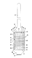
図2及び図3は、緊締装置20を第1側(以下、上側36)及び第2側(以下、下側38)の平面図において概略的に示す。本明細書による緊締装置20及び参照装置18が使用される際、下側38は大腿部16を向き、上側36は大腿部16から離れる方を向く。
2 and 3 schematically show the tightening
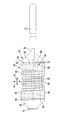
緊締装置20は、この場合包帯40として、特に圧縮包帯として構成される。包帯40は、標識装置22用に表面上を互いに対して交差方向に整列する2つの広がり方向42、44に延びる支持体46を含む。包帯40が支持体に適用される際、支持体46は形状において変更可能であり、大腿部16の輪郭に適合可能である。従って、支持体46は全体としては包帯40のように、大腿部16に確実嵌合により適用することができるのであり、大腿部を包囲することができる。本明細書による使用中、包帯40が大腿部16に適用され、支持体46が変形を受ける際、広がり方向42は大腿部16の周方向に走り、広がり方向44は大腿部16の長手方向に走る。
The tightening
支持体46は平面視において略矩形形状であり、2つの長手方向側48、49は、広がり方向42において互いに平行に延び、交差方向側50、51は広がり方向44において互いに平行に延びる。長手方向側49はその中間区域に弓形の湾曲52を有するのであり、そのため支持体46の縁部で湾曲52の領域には凹部54が配置される。
The
この場合、支持体46は編物58として構成されたテキスタイル材料56である。従って、支持体46は故に包帯40は、製造の観点から、単純かつ費用効果的に生産することができる。この場合、編物58は異なる織り方である2つの領域を有し、従って使用する織り方及び糸が異なるおかげで、支持体46はその領域に、異なる特徴を有する。
In this case, the
特に編物58は、支持体46がその広がりの表面において、互いに対して交差方向に整列する二方向へと、特に広がり方向42及び広がり方向44へと弾力的に伸縮可能であるように作成される。以下でより詳細に説明するように、包帯40を適用する際、大腿部16を圧縮するために、支持体46は伸縮することができる。
In particular, the knitted
編物58は、支持体46の平面視において略矩形形状を有する第1伸縮領域60を有する。伸縮領域60は支持体46の中央に位置し、第2伸縮領域62により包囲される。伸縮領域62は、伸縮領域60を囲み、伸縮領域の縁部を形成する。伸縮領域62は、更に長手方向側48、49、及び交差方向側50、51を形成する。
The knitted
編物58の構成のおかげで、伸縮領域60、62は互いに、製造の観点から単純な仕方で、編成により1回の作業で接続される。
Thanks to the configuration of the knitted
この場合、第1伸縮領域60は二重の高伸縮弾力性の、例えば綾織の編物である。綾織は、特に弾力的な編糸を有する。伸縮領域62は、低弾力性の糸を用いた半管状織の編物である。結果として、伸縮領域60は、両広がり方向42、44に(及び、広がり方向42、44の重ね合わせから生じ、支持体46の表面においてこれらの方向に対してそれぞれ角度を成して整列する方向に)、伸縮領域62よりも大きい伸縮可能性を有する。伸縮領域60の伸縮可能性は、広がり方向44では広がり方向42におけるよりも大きい。
In this case, the first
支持体46は、下側38に複数の摩擦係数増加要素64(以下、単純にする目的で摩擦要素64)を有する。この場合、摩擦要素64は点状であり、例えば凡そピンヘッドの寸法である。摩擦要素64は、好ましくはシリコーン材料製である。
The
支持体46は、長手方向側48を有する縁部に摩擦要素64を含む。摩擦要素64は、長手方向側48と平行な二重列になって延び、互いから一様に離間する。摩擦要素は、実質、支持体46の長さ部分全体にわたって延び、両方の伸縮領域60、62に配置される。
The
支持体46は、長手方向側49を形成する対向する縁部に各々が摩擦要素64を備えた第1区域66及び第2区域68と、これらの区域間に横たわる区域70とを有し、区域70には摩擦要素64がない。区域66は、広がり方向42において凹部54と交差方向側50との間に配置され、区域68は、凹部54と交差方向側51との間に配置される。区域70は、支持体46の中央で凹部54の長さ部分を幾分越えて延びる。各区域66、68では、摩擦要素64は長手方向側49と平行な二重列になって延び、支持体46上でそれぞれ互いから等距離の所に配置される。
The
摩擦要素64により、包帯40と大腿部16との間で局部的に摩擦を増加させることが可能になる。区域70の領域では、摩擦は特別に低く保たれる。
The
包帯40は、寸法を調整可能な包帯である。包帯は、図2及び図3に示す開放した解放状態から、包帯40が自らの内部で閉じた適用状態(図1、図4、図5)に転移可能である。この目的で、包帯40は固定要素、つまり、ストラップ72と、このストラップと相互作用するアイレット74とを有する。ストラップ72は、硬化要素75を介して交差方向側50に固定されるのであり、(包帯40が平坦に置かれる際には)広がり方向42に沿って延びる。
The
硬化要素75は、例えば、螺旋ばね又は例えばプラスチック製のストリップが中に配置されたファブリックトンネルを含む。交差方向側50の近くには、ストラップ72上に、フック‐ループファスナ76の形態の固定要素が設けられ、フック‐ループファスナ76に自らの内部で閉じるやり方でストラップ72を接着式に取付けることができる。
The stiffening
アイレット74は、保持区域78の側に取付けられる。保持区域78は、反対側で交差方向側51の硬化要素79を介して支持体46に接続される。硬化要素79は、形態及び機能において硬化要素75に対応する。
The
大腿部16上で包帯40を適用状態に転移するために、下側38がその皮膚80上に非侵襲的に位置決めされる(図4)。包帯40は伸縮領域60、62の弾力性とは逆に、好ましくは広がり方向42において伸縮される。包帯40は大腿部16上で、好ましくは膝蓋骨82上の軟組織が凹部54に係合するように、位置決めされる。
In order to transfer the
適用状態において、包帯40はストラップ72がアイレット74を通して案内され、包帯40が緊張して自らの内部でフック‐ループファスナ46に取付けられることにより固定される。硬化要素75、79は、包帯が広がり方向44においてその形状を維持し、支持体が緊張に起因して先細にならないことを確実にする。
In the applied state, the
膝蓋骨82上の軟組織が凹部54に係合する際、伸縮領域60は、特に摩擦要素64のない区域70の領域において、大腿部16の四頭筋の腱上に配置される。
When soft tissue on the
包帯40、故に参照装置18は、大腿部16に患者に優しくかつ使い勝手のよい仕方で非侵襲的に固定可能である。適用状態において、包帯40は大腿部16を圧縮する。これによって、皮膚、軟組織、及び筋肉の互いに対する移動、及び大腿骨に対する移動が制限される。それ故に、包帯40が大腿部16に対して、特に大腿骨に対して移動する能力も低減する。
The
また、発生する皮膚、軟組織、及び筋肉の相対移動を、実質、支持体46内で吸収することができる。この目的で、支持体46を、伸縮領域60、62を備えた編物58として製造することが特に有利であると分かる。伸縮領域60、62は、広がり方向42、44のうちの少なくとも1つへのその伸縮可能性に関して相違する。伸縮領域60、62は、大腿部16内での移動が支持体46によりかなりの程度吸収されるように編成される。特に、第1伸縮領域60でその中央では(広がり方向42に関して)、特に、支持体46内での移動がほとんど生じない。第1伸縮領域60は、摩擦要素64のない区域70を含む。摩擦要素64、及びその支持体46上での配置は、大腿部16の特別な圧縮によって、移動を支持体46に特別に導入する包帯40の能力を改良する。
Further, the relative movement of the generated skin, soft tissue, and muscle can be substantially absorbed within the
上で言及したように、摩擦要素64のない区域70を設けることは、大腿部16と包帯40との間の摩擦を局部的に低く保つことができるという利点を有する。例えば、脚部が伸長及び屈曲する間、区域70の皮膚80は支持体46に僅かな程度にしか擦り付けられないため、軟部が変位することにより、支持体46は係合しない又は僅かな程度にしか係合しない。従って、脚部が伸長又は屈曲する間、区域70にある又はこの区域の近くにある上側36の標識装置が、大腿骨に対するその位置を維持することもできる有効な参照を成すことができる。この目的で、支持体46が広がり方向42に沿ったものよりも大きい、広がり方向44に沿った伸縮可能性を有することも有利である。
As mentioned above, providing the
膝蓋骨82又は膝蓋骨82上の軟組織が四頭筋の腱上で凹部54及び区域70の領域に配置される場合、この領域における支持体46の移動は特に少ない。このことは、四頭筋の腱の大腿部16内の他の軟組織及び他の筋肉に対する可動性が比較的低い結果である。
When the
この理由で、緊締装置20は、標識装置22が固定可能である保持部84を区域70に含む。図1〜図3において保持部84は図示しない。
For this reason, the clamping
保持部84は凡そ角錐台を成す角柱形状であり、支持体46に、特に伸縮領域60に固定される。保持部84は、第1層86、第2層88、及び第3層90を備えた多層構造である。この場合、層86〜90は例えばシリコーン材料製である。これらの層が、異なる変形可能性を有し、変形可能性が好ましくは層86から層88を介して層90まで減少すると好都合である。これによって、依然として支持体46で生じる移動を保持部84内で吸収することができるのであり、この移動は標識装置22に僅かな程度にしか伝達されない又は伝達されない。保持部84は、層86を介して支持体46の編物58に係合し、編物内に部分的に埋め込まれるのであり、これによって保持部84が支持体46に固定される。
The holding
保持要素92が層90に固定され、保持要素92には標識装置22が固定される又は特に解放可能に固定可能である。この場合、保持要素92は層90内に埋め込まれる、例えば注型される。標識要素アレイ26は保持要素92に、例えば、ねじ込み、締付け、錠止、接着により、フック‐ループファスナ又は同様のものにより、力ロック式及び/又はポジティブロック式で固定することができる。
A holding
参照装置18を患者14に非侵襲的に緊締する可能性により、身体部分、例えば大腿部16等を、ナビゲーションシステム10を用いて空間追跡する可能性が、患者にとって優しいものとなる。上で言及したように、術前、術中、及び術後の使用が可能である。緊締が患者に穏やかであるにも拘わらず、上で説明したような緊締装置20の構成のおかげで、十分に正確な参照を達成することができる。
The possibility of non-invasively fastening the
本発明による緊締装置及び参照装置の更なる好適な実施形態を以下で検討することにする。同じである又は同じ効果を有する特性及び構成要素については、大部分が同一である参照符号を使用することにする。 Further preferred embodiments of the clamping device and the reference device according to the invention will be discussed below. For features and components that are the same or have the same effect, the same reference numerals will be used.
図6は、参照符号100を付した緊締装置の第2の好適な実施形態を通る断面図を、図5と同様の仕方で概略的に示す。緊締装置100は包帯40を含む。包帯40に取付けられるのは、その機能において保持要素92に対応する保持部104である。図面には示さない標識装置を保持部104に、例えばねじ込み、締付け、錠止、接着により、又はフック‐ループファスナにより、固定する又は特に解放可能に取付けることができる。
FIG. 6 schematically shows a cross-sectional view through a second preferred embodiment of the clamping device labeled with
保持部104は上側36に固定されるのであり、多孔質体106を含む。多孔質体106は多数のキャビティ108を有する。多孔質体106は、キャビティ108の平均寸法が、保持部104の支持体46を向く側から、保持部104の支持体46から離れる方を向く側へと減少するように構成される。特に、平均寸法は連続的に減少させることができる。結果として、保持部104の変形可能性が、支持体46を向く側から支持体46から離れる方を向く側へと減少し、保持部104は、支持体46にて支持体から距離をおいたところでよりも軟らかくなる。従って、保持部84を用いたときのように支持体46の移動を保持部104内で吸収することが可能であり、これによって、これらの移動は、保持部104の支持体46から離れる方を向く側の連結点110に固定可能である標識装置(図示せず)に、伝達されない又は僅かな程度にしか伝達されない。例えば、標識装置22が使用される。
The holding
図7は、緊締装置122及び標識装置124を備えた更なる参照装置120を示す。緊締装置122は、保持部84が設けられていないことを別とすれば、構成において緊締装置20と同一である。
FIG. 7 shows a
この場合、標識装置124はコンパクトな構造であり、凡そ台形形状であるプレート状の担持要素126とこの担持要素の隅部に固定された標識要素128とを有する。これらの要素は、剛性の標識要素アレイ126を形成する。標識装置124は、特に低い構造高さを有し、比較的軽量である。慣性が低減されるおかげで、標識装置124と緊締装置122との相対移動が特に少ない。構造高さが低いおかげで、標識装置124と支持体46との相対移動によってさえも、位置データの歪曲がほんの僅かなものにしかならず、従って参照装置120を用いれば、大腿部16を空間追跡する際、位置データを高精度にすることが達成可能である。構造的にいえば、標識装置124は支持体46に例えば接着により又はフック‐ループファスナにより、容易に固定することができる。
In this case, the marking
図8は、更なる緊締装置130を図2に対応する仕方で表す。緊締装置130は、大部分は緊締装置20と同一である。緊締装置は、保持部84又は保持部104を含むことができ又は緊締装置122のように、保持部を持たなくてもよい。標識装置124は、例えば緊締装置130と相互作用して参照装置を形成することができる。
FIG. 8 represents a
緊締装置130には2つの伸縮領域132、134が設けられ、2つの伸縮領域132、134は伸縮領域60、62に対応する。伸縮領域134は伸縮領域132を包囲する。伸縮領域132は、支持体46の平面視において、2つの拡張区域136、138が互いから距離をおいたところに配置された先細の輪郭を有する。これらの拡張区域間に狭窄区域140が配置される。区域136〜140は、広がり方向42に沿って交差方向側50、51間の中央に配置される。広がり方向44では、拡張区域136は長手方向側48に隣接し、拡張区域138は長手方向側49に隣接する。
The
緊締装置130は、そして緊締装置122も同じように、図面には示さないそのそれぞれの下側に摩擦要素を有する。
The
緊締装置20と合わせて説明したような、達成可能な利点を緊締装置100、122、及び130を使用しても達成することができる。
The achievable advantages, as described in conjunction with the clamping
図8は、緊締装置130に加えて、この場合は緊締装置130並びにデータ処理装置152を含む医療機器150を示す。データ処理装置152は、好ましくは手で保持可能かつ携帯式であり、例えばタブレットコンピュータの形態である。それに応じて、データ処理装置152は、好ましくは不可欠な構成要素としてディスプレイユニット154を包含することができる。
FIG. 8 shows a
データ処理装置152内に、図8に概略的に示す光検出ユニット156も一体化される。光検出ユニット156は、特にデジタルカメラを含む。
In the
機器150が使用中であるとき、検出ユニット156は、大腿部16に固定された包帯40に特にその支持体46に向けられる。支持体46を異なる変形領域に分割できるかどうかについて、検出ユニットにより提供される画像信号がデータ処理装置152により検査される。大腿部16が移動し、これに関連して皮膚、軟組織、筋肉、及び大腿骨が互いに対して変位し、包帯40が大腿部16上で移動することがあり得る結果として、支持体46は、変形の異なる領域を有することができる。これらの領域は、伸縮領域132、134とは相違してもよい。一方、上で既に説明したようにデータ処理装置152は、緊締装置130に関して、例えば支持体46のほとんど変形しない領域が伸縮領域132にて凹部54の近くに位置することを判定する。
When the
変形領域を判定するために、データ処理装置152は織り方のおかげで、例えば変形領域136、140の織り方が異なるおかげで、例えば支持体46の、1つ以上の色又は表面ストラクチャ、例えば支持体46の糸の色又は表面ストラクチャを使用することができる。それに応じて、データ処理装置152は、支持体46のどの領域が比較的僅かな程度にしか変形しないのかを画像信号に基づいて自動的に判断する画像処理プログラムを包含することができる。この目的で、例えば有限要素法が利用される。
In order to determine the deformation area, the
操作者には、ディスプレイユニット154上で支持体46の画像を示すことができる。この画像において、好ましくは異なる変形領域が特徴付けられる。極力安定した参照を得るために、標識装置、例えば標識装置124が、支持体46上のどこに有利に置かれるべきかについての表示が操作者に与えられることが好都合である。
The operator can be shown an image of the
当然ながら、一体化されたデータ処理装置152は、緊締装置100、122、及び20と共に使用することもできる。例えば参照装置120に関して、標識装置124は、緊締装置122上の図7に示す位置に置かれた。というのも、安定した参照にとってこの位置が適切であると分かったからである。
Of course, the integrated
Claims (15)
表面上を互いに角度を成して整列する2つの広がり方向(42、44)に延びると共に、前記標識装置(22;124)が固定される又は固定可能である前記身体部分(16)の輪郭に形状が適合可能である支持体(46)を含み、
前記支持体(46)が、該支持体(46)の広がりの表面において弾力的に伸縮可能であると共に、第1伸縮領域(60;132)及び少なくとも1つの第2伸縮領域(62;134)を含み、
前記第2伸縮領域の、前記支持体(46)の広がりの表面における少なくとも1つの方向(42、44)での伸縮可能性が、前記第1伸縮領域(60;132)の伸縮可能性よりも小さい、
緊締装置(20;100;122;130)において、
前記緊締装置(20;100)が少なくとも1つの保持部(84;104)を含み、該少なくとも1つの保持部(84;104)が前記支持体(46)に固定されること、及び
前記標識装置(22)又は前記標識装置(22)の標識要素が、前記保持部(84;104)の前記支持体(46)から離れる方を向く側で、力ロック式及び/又はポジティブロック式により固定される又は固定可能であること、
を特徴とする緊締装置。 A medical marking device (22; 124) comprising two or more marking elements (24; 128) in a body part (16) of a patient (14), in particular in the thigh, for non-invasive fastening A tightening device,
On the contour of the body part (16) that extends in two spreading directions (42, 44) that are angled to each other on the surface and to which the marking device (22; 124) is fixed or fixable A support (46) that is conformable in shape;
The support (46) is elastically stretchable on the surface of the spread of the support (46) and has a first stretch region (60; 132) and at least one second stretch region (62; 134). Including
The stretchability of the second stretchable region in at least one direction (42, 44) on the surface of the spread of the support (46) is greater than the stretchability of the first stretchable region (60; 132). small,
In the clamping device (20; 100; 122; 130),
The clamping device (20; 100) includes at least one holding portion (84; 104), the at least one holding portion (84; 104) being fixed to the support (46); and the marking device (22) or the marking element of the marking device (22) is fixed by force-locking and / or positive-locking on the side of the holding part (84; 104) facing away from the support (46). Can be fixed or fixed,
Tightening device characterized by.
前記少なくとも1つの第2伸縮領域(62;134)が、前記第1伸縮領域(60;132)を包囲すること、及び/又は
前記支持体(46)が、平面視において、矩形の又は略矩形の輪郭を有すること、
を特徴とする緊締装置。 The tightening device according to claim 1 or 2,
The at least one second stretchable region (62; 134) surrounds the first stretchable region (60; 132), and / or the support (46) is rectangular or substantially rectangular in plan view. Having an outline of
Tightening device characterized by.
前記支持体(46)が、編物(58)、経編物、又は織物の形態のテキスタイル材料(56)であること、又は、
前記支持体(46)がこのようなテキスタイル材料(56)を含み、好ましくは、前記第1伸縮領域(60;132)と前記少なくとも1つの第2伸縮領域(62;136)とが、編成、経編成、又は製織により互いに接合されること、
を特徴とする緊締装置。 The tightening device according to any one of claims 1 to 3,
The support (46) is a textile material (56) in the form of a knitted fabric (58), warp knitted fabric or woven fabric, or
The support (46) comprises such a textile material (56), preferably the first stretch region (60; 132) and the at least one second stretch region (62; 136) are knitted, Joined together by warp knitting or weaving,
Tightening device characterized by.
前記第1伸縮領域(60;132)が、綾織の編物(58)であり又は綾織の編物を含むこと、及び/又は、
前記少なくとも1つの第2伸縮領域(62;134)が、半管状織の編物(58)である又は半管状織の編物を含むこと、
を特徴とする緊締装置。 The tightening device according to claim 4 or 5,
The first stretch region (60; 132) is a twill knitted fabric (58) or comprises a twill knitted fabric, and / or
The at least one second stretch region (62; 134) is a semi-tubular knitted fabric (58) or comprises a semi-tubular knitted fabric;
Tightening device characterized by.
該参照装置が、少なくとも2つ以上の外科用標識要素(24、128)を備えた標識装置(22;124)を含み、前記少なくとも2つ以上の外科用標識要素(24、128)が、放射線を反射及び/又は放出すると共に患者(14)の身体上の参照を規定するための標識要素アレイ(26)を形成するように構成され、
該参照装置が更に、請求項1〜12のいずれか1項に記載の緊締装置(20;122)を含み、前記標識装置(22;124)が、前記緊締装置(20;122)に好ましくは解放可能に固定可能である又は固定される、
参照装置。 A medical reference device,
The reference device includes a marking device (22; 124) with at least two or more surgical marking elements (24, 128), wherein the at least two or more surgical marking elements (24, 128) are radiation. Are configured to form a marker element array (26) for reflecting and / or emitting and defining a reference on the patient (14) body,
The reference device further comprises a clamping device (20; 122) according to any one of claims 1 to 12, wherein the marking device (22; 124) is preferably in the clamping device (20; 122). Releasably fixable or fixed,
Reference device.
前記標識要素アレイ(26;129)が剛性の構造であり、前記標識要素(22;128)が、互いにしっかり接続されると共に、前記緊締装置(20;122)に一緒に固定可能であること、又は
前記標識要素アレイが非剛性の構造であり、2つ以上の標識要素が、互いに対して適所で変更可能であること、
を特徴とする参照装置。 14. The reference device according to claim 13, comprising:
The marker element array (26; 129) is a rigid structure, and the marker elements (22; 128) are firmly connected to each other and can be fixed together on the clamping device (20; 122); Or the marker element array is a non-rigid structure and two or more marker elements can be changed in place relative to each other,
A reference device.
請求項1〜12のいずれか1項に記載の緊締装置と、前記緊締装置が空間移動すると患者(14)の身体部分(16)に取り付けられた前記緊締装置(20;100;122;130)の画像を検出可能である光検出ユニット(156)と、該画像に関する画像信号を前記光検出ユニット(156)により提供されるように適合されているデータ処理装置(152)とを含み、
前記データ処理装置(152)が、前記画像信号に基づいて前記支持体(46)を異なる変形領域に分割するように構成及びプログラムされ、前記緊締装置(20;100;122;130)の移動が測定可能である結果として、少なくとも2つの変形領域が変形に関して相違する、
医療機器。 A medical device,
13. The clamping device according to any one of claims 1 to 12, and the clamping device (20; 100; 122; 130) attached to a body part (16) of a patient (14) when the clamping device moves in space. A light detection unit (156) capable of detecting a plurality of images, and a data processing device (152) adapted to provide an image signal relating to the image provided by the light detection unit (156),
The data processing device (152) is configured and programmed to divide the support (46) into different deformation regions based on the image signal, and movement of the clamping device (20; 100; 122; 130) As a result of being measurable, at least two deformation regions differ with respect to deformation,
Medical equipment.
Applications Claiming Priority (3)
| Application Number | Priority Date | Filing Date | Title |
|---|---|---|---|
| DE102014104800.8A DE102014104800A1 (en) | 2014-04-03 | 2014-04-03 | Medical fastening device and referencing device and medical instruments |
| DE102014104800.8 | 2014-04-03 | ||
| PCT/EP2015/056383 WO2015150185A1 (en) | 2014-04-03 | 2015-03-25 | Medical securing device and referencing device, and medical instrumentation |
Publications (3)
| Publication Number | Publication Date |
|---|---|
| JP2017509428A JP2017509428A (en) | 2017-04-06 |
| JP2017509428A5 JP2017509428A5 (en) | 2018-05-10 |
| JP6490708B2 true JP6490708B2 (en) | 2019-03-27 |
Family
ID=52774220
Family Applications (1)
| Application Number | Title | Priority Date | Filing Date |
|---|---|---|---|
| JP2016559966A Active JP6490708B2 (en) | 2014-04-03 | 2015-03-25 | Medical fastening device and reference device, and medical device |
Country Status (7)
| Country | Link |
|---|---|
| US (1) | US10507062B2 (en) |
| EP (1) | EP3125805B1 (en) |
| JP (1) | JP6490708B2 (en) |
| CN (1) | CN106163446B (en) |
| DE (1) | DE102014104800A1 (en) |
| ES (1) | ES2681501T3 (en) |
| WO (1) | WO2015150185A1 (en) |
Families Citing this family (29)
| Publication number | Priority date | Publication date | Assignee | Title |
|---|---|---|---|---|
| US11864839B2 (en) | 2012-06-21 | 2024-01-09 | Globus Medical Inc. | Methods of adjusting a virtual implant and related surgical navigation systems |
| US11786324B2 (en) | 2012-06-21 | 2023-10-17 | Globus Medical, Inc. | Surgical robotic automation with tracking markers |
| US11793570B2 (en) | 2012-06-21 | 2023-10-24 | Globus Medical Inc. | Surgical robotic automation with tracking markers |
| US11857149B2 (en) | 2012-06-21 | 2024-01-02 | Globus Medical, Inc. | Surgical robotic systems with target trajectory deviation monitoring and related methods |
| US11253327B2 (en) | 2012-06-21 | 2022-02-22 | Globus Medical, Inc. | Systems and methods for automatically changing an end-effector on a surgical robot |
| US11857266B2 (en) | 2012-06-21 | 2024-01-02 | Globus Medical, Inc. | System for a surveillance marker in robotic-assisted surgery |
| US12004905B2 (en) | 2012-06-21 | 2024-06-11 | Globus Medical, Inc. | Medical imaging systems using robotic actuators and related methods |
| US11864745B2 (en) | 2012-06-21 | 2024-01-09 | Globus Medical, Inc. | Surgical robotic system with retractor |
| US11963755B2 (en) | 2012-06-21 | 2024-04-23 | Globus Medical Inc. | Apparatus for recording probe movement |
| US11045267B2 (en) | 2012-06-21 | 2021-06-29 | Globus Medical, Inc. | Surgical robotic automation with tracking markers |
| US11896446B2 (en) | 2012-06-21 | 2024-02-13 | Globus Medical, Inc | Surgical robotic automation with tracking markers |
| US11974822B2 (en) | 2012-06-21 | 2024-05-07 | Globus Medical Inc. | Method for a surveillance marker in robotic-assisted surgery |
| US11317971B2 (en) | 2012-06-21 | 2022-05-03 | Globus Medical, Inc. | Systems and methods related to robotic guidance in surgery |
| US11298196B2 (en) | 2012-06-21 | 2022-04-12 | Globus Medical Inc. | Surgical robotic automation with tracking markers and controlled tool advancement |
| US11399900B2 (en) | 2012-06-21 | 2022-08-02 | Globus Medical, Inc. | Robotic systems providing co-registration using natural fiducials and related methods |
| US11589771B2 (en) | 2012-06-21 | 2023-02-28 | Globus Medical Inc. | Method for recording probe movement and determining an extent of matter removed |
| US10624710B2 (en) | 2012-06-21 | 2020-04-21 | Globus Medical, Inc. | System and method for measuring depth of instrumentation |
| US10799298B2 (en) | 2012-06-21 | 2020-10-13 | Globus Medical Inc. | Robotic fluoroscopic navigation |
| DE102016109173A1 (en) | 2015-11-19 | 2017-05-24 | Aesculap Ag | Medical-technical coordinate measuring device and medical-technical coordinate measuring method |
| US11883217B2 (en) | 2016-02-03 | 2024-01-30 | Globus Medical, Inc. | Portable medical imaging system and method |
| EP3261572B1 (en) * | 2016-05-20 | 2018-08-01 | Brainlab AG | Tracking reference fixation support |
| DE102016113000A1 (en) | 2016-07-14 | 2018-01-18 | Aesculap Ag | Endoscopic device and method for endoscopic examination |
| EP3369394B1 (en) * | 2017-03-03 | 2020-06-10 | Globus Medical, Inc. | System for a surveillance marker in robotic-assisted surgery |
| USD897537S1 (en) * | 2017-04-18 | 2020-09-29 | Intuitive Surgical Operations, Inc. | Surgical apparatus |
| DE102018105834A1 (en) | 2018-03-14 | 2019-09-19 | Aesculap Ag | Medical technology system and method for non-invasive tracking of an object |
| CN109009436B (en) * | 2018-08-24 | 2023-11-10 | 真健康(北京)医疗科技有限公司 | A body surface positioning device for infrared navigation |
| US12150728B2 (en) | 2021-04-14 | 2024-11-26 | Globus Medical, Inc. | End effector for a surgical robot |
| USD1120320S1 (en) | 2023-08-18 | 2026-03-24 | Mako Surgical Corp. | Surgical tracker |
| USD1117755S1 (en) | 2023-08-18 | 2026-03-10 | Mako Surgical Corp. | Surgical tracker |
Family Cites Families (79)
| Publication number | Priority date | Publication date | Assignee | Title |
|---|---|---|---|---|
| US1428465A (en) * | 1919-02-04 | 1922-09-05 | William H Horn & Brother Inc | Kneecap or elbow bandage |
| US1445840A (en) * | 1921-02-17 | 1923-02-20 | Alfred A C Malcolm | Girdle |
| US1985210A (en) * | 1931-12-19 | 1934-12-18 | Berkshire Knitting Mills | Ornamented knitted fabric and method of making the same |
| US2246246A (en) * | 1936-08-12 | 1941-06-17 | Textile Machine Works | Article of wearing apparel and method of making it |
| US2301541A (en) * | 1940-01-09 | 1942-11-10 | Vanity Fair Silk Mills | Method of knitting stockings with strain absorbing fabrics |
| US2977782A (en) * | 1959-04-29 | 1961-04-04 | Hanes Hosiery Mills Company | Knitted fabric |
| US3375530A (en) * | 1966-01-11 | 1968-04-02 | Chadbourn Gotham Inc | Briefs and method of making |
| US3421503A (en) * | 1966-10-12 | 1969-01-14 | David Kaplan | Binder |
| US3667462A (en) * | 1970-06-04 | 1972-06-06 | Jacob R Moon | Orthopedic, surgical, athletic and animal bandaging |
| US3831467A (en) * | 1973-03-16 | 1974-08-27 | R Moore | Knee brace |
| CH657044A5 (en) * | 1982-05-27 | 1986-08-15 | Senn & Co Ag | ELASTIC KNEE BANDAGE. |
| US4614179A (en) * | 1985-08-08 | 1986-09-30 | Electro-Biology, Inc. | Medical appliance |
| US5125116A (en) * | 1990-12-12 | 1992-06-30 | Ridgeview, Inc. | Sock with simulated stirrup |
| DE4101965A1 (en) * | 1991-01-24 | 1992-07-30 | Beiersdorf Ag | JOINT BANDAGE |
| US5261871A (en) * | 1991-12-12 | 1993-11-16 | Greenfield Raphael L | Orthopedic device |
| US5216700A (en) * | 1992-02-18 | 1993-06-01 | George Cherian | Tape having graduated scale providing location indicia during x-ray processes |
| US5376067A (en) * | 1992-10-28 | 1994-12-27 | Daneshvar; Yousef | Pressure bandages and dressings |
| DE4237389A1 (en) * | 1992-11-05 | 1994-05-11 | Beiersdorf Ag | Elastic tubular bandage for knee joint |
| FR2703243B1 (en) * | 1993-04-02 | 1995-05-05 | Cognon Morin | Compression article for medical use for a leg or an arm. |
| US5540063A (en) * | 1995-05-15 | 1996-07-30 | Allstate Hosiery Sales, Inc. | Stocking |
| US6117121A (en) * | 1995-12-11 | 2000-09-12 | Kimberly-Clark Worldwide, Inc. | Absorbent article using extensible leg cuffs |
| AU740715B2 (en) * | 1997-05-08 | 2001-11-15 | Ethicon Inc. | Bandage compression indicator |
| US6279579B1 (en) | 1998-10-23 | 2001-08-28 | Varian Medical Systems, Inc. | Method and system for positioning patients for medical treatment procedures |
| US7853311B1 (en) * | 1999-04-23 | 2010-12-14 | 3M Innovative Properties Company | Surgical targeting system |
| AU7396900A (en) * | 1999-09-17 | 2001-04-24 | University Of British Columbia, The | Positioning method and apparatus for mounting a tracker |
| ITCO20000005A1 (en) * | 2000-02-21 | 2001-08-21 | Franco Sciacca | METHOD AND EQUIPMENT FOR AUTOMATIC PRODUCTION OF TUBULAR KNITTED ITEMS CONFORMED WITH GRADUATED ANATOMICAL SUPPORT AND CONTAINMENT AND |
| US7326227B2 (en) | 2001-02-28 | 2008-02-05 | Richard G. Dedo | Tourniquet padding |
| US20050026539A1 (en) * | 2002-07-02 | 2005-02-03 | Sara Lee Corporation | Circular knitted garments having bands with integrally knit cushion loops |
| FI117886B (en) * | 2002-07-29 | 2007-04-13 | Nexstim Oy | Position indicator frame and method for supporting a position indicator frame |
| DE10335595A1 (en) | 2002-08-02 | 2004-02-26 | Tecmedic Gmbh | Motion capture method for determination of the spatial positions of markers in a 3D volume from 2D digital images for use in motion capture systems so that the marker positions can be related to a coordinate system |
| US7869861B2 (en) | 2002-10-25 | 2011-01-11 | Howmedica Leibinger Inc. | Flexible tracking article and method of using the same |
| US7209776B2 (en) | 2002-12-03 | 2007-04-24 | Aesculap Ag & Co. Kg | Method of determining the position of the articular point of a joint |
| US20050049485A1 (en) | 2003-08-27 | 2005-03-03 | Harmon Kim R. | Multiple configuration array for a surgical navigation system |
| EP1673146B1 (en) | 2003-09-30 | 2012-11-14 | Koninklijke Philips Electronics N.V. | Target tracking apparatus for radiation treatment planning and delivery |
| DE20315470U1 (en) * | 2003-10-08 | 2003-12-11 | Aesculap Ag & Co. Kg | Body part position determining device using navigation system and marker on body part, determines position of fixed structure relative to navigation system using data from position-determining device |
| US9440089B2 (en) * | 2003-12-05 | 2016-09-13 | Rio Grande Neurosciences, Inc. | Apparatus and method for electromagnetic treatment of neurological injury or condition caused by a stroke |
| US20050245820A1 (en) | 2004-04-28 | 2005-11-03 | Sarin Vineet K | Method and apparatus for verifying and correcting tracking of an anatomical structure during surgery |
| US7882713B2 (en) * | 2005-03-16 | 2011-02-08 | Hui Tseng | Length-ways stretchable elastic band |
| US9867669B2 (en) | 2008-12-31 | 2018-01-16 | Intuitive Surgical Operations, Inc. | Configuration marker design and detection for instrument tracking |
| WO2008009136A1 (en) | 2006-07-21 | 2008-01-24 | Orthosoft Inc. | Non-invasive tracking of bones for surgery |
| US20090043232A1 (en) * | 2007-01-23 | 2009-02-12 | Borschneck Anthony G | Sterile Tensor Cravats And Methods For Storing And Deploying Same |
| CA2578927C (en) * | 2007-02-19 | 2011-09-27 | Ray Arbesman | Precut adhesive body support articles and support system |
| US8771188B2 (en) * | 2007-06-20 | 2014-07-08 | Perception Raisonnement Action En Medecine | Ultrasonic bone motion tracking system |
| US9422095B2 (en) | 2007-07-31 | 2016-08-23 | Phoenix Contact Gmbh & Co. Kg | Marking object |
| DE102007036374A1 (en) * | 2007-07-31 | 2009-02-05 | Phoenix Contact Gmbh & Co. Kg | Marking object and marking device |
| EP2164419A1 (en) * | 2007-11-08 | 2010-03-24 | Orthosoft, Inc. | Trackable reference device for computer-assisted surgery |
| US20090124949A1 (en) | 2007-11-12 | 2009-05-14 | Uriel Rosen | Versatile medical article |
| DE202008003637U1 (en) | 2008-03-04 | 2008-05-08 | Aesculap Ag & Co. Kg | Surgical detection device and surgical navigation system |
| EP2252230A1 (en) | 2008-03-13 | 2010-11-24 | Orthosoft, Inc. | Tracking cas system |
| CN201167953Y (en) | 2008-03-13 | 2008-12-24 | 李庆国 | Magnetic resonance craniocerebral puncturing and locating cap |
| US8114117B2 (en) * | 2008-09-30 | 2012-02-14 | Tyco Healthcare Group Lp | Compression device with wear area |
| JP5255897B2 (en) * | 2008-05-12 | 2013-08-07 | 岡本株式会社 | socks |
| DE102008052860B4 (en) * | 2008-10-23 | 2011-01-05 | Otto Bock Healthcare Gmbh | joint bandage |
| EP2198801A1 (en) * | 2008-12-19 | 2010-06-23 | BrainLAB AG | Marker application device for applying a marker device |
| WO2011023232A1 (en) | 2009-08-27 | 2011-03-03 | Brainlab Ag | Disposable and radiolucent reference array for optical tracking |
| EP2298223A1 (en) | 2009-09-21 | 2011-03-23 | Stryker Leibinger GmbH & Co. KG | Technique for registering image data of an object |
| US20110105828A1 (en) * | 2009-10-30 | 2011-05-05 | Magnetic Acupuncture, LLC | Methods of treating a body part |
| DE102010011589A1 (en) | 2010-03-16 | 2011-09-22 | Siemens Aktiengesellschaft | Reference structure for implementation of medical procedure for patient based on two or three-dimensional x-ray images, has film provided with positioning arrangement with glue layer on flat side for fixation of film on skin of patient |
| US20130006120A1 (en) | 2010-03-17 | 2013-01-03 | Alexander Druse | Marker for a medical navigation system with a laser tracker |
| US9232637B2 (en) * | 2010-09-22 | 2016-01-05 | Koninklijke Philips N.V. | Knitted textile substrate with different stitch patterns and electronic textile |
| US9125624B2 (en) | 2010-11-23 | 2015-09-08 | Claronav Inc. | Method and apparatus for automated registration and pose tracking |
| CA2830918C (en) * | 2011-03-31 | 2022-07-26 | Felmont Farrell Eaves, Iii | Force modulating tissue bridge |
| CN102727308A (en) | 2011-04-01 | 2012-10-17 | 上海优益基医疗器械有限公司 | Positioning reference frame capable of being repeatedly mounted and dismounted used for surgery navigation system |
| CN102258399B (en) * | 2011-04-28 | 2012-11-28 | 上海交通大学 | Non-invasive real-time tracker coupled with ultrasonic ranging and optical localization |
| JP5271388B2 (en) * | 2011-07-04 | 2013-08-21 | ピアック株式会社 | X-ray detection adhesive bandage and method for producing X-ray detection adhesive bandage |
| US10027952B2 (en) | 2011-08-04 | 2018-07-17 | Trx Systems, Inc. | Mapping and tracking system with features in three-dimensional space |
| AU2013232261B2 (en) * | 2012-03-12 | 2015-12-10 | Medi Manufacturing Inc. | Adjustable elastic profile compression garment |
| CA2777975C (en) * | 2012-05-24 | 2016-06-28 | Ray Arbesman | Contusion tape |
| WO2013182224A1 (en) | 2012-06-05 | 2013-12-12 | Brainlab Ag | Improving the accuracy of navigating a medical device |
| EP2863827B1 (en) | 2012-06-21 | 2022-11-16 | Globus Medical, Inc. | Surgical robot platform |
| WO2014009967A1 (en) * | 2012-07-10 | 2014-01-16 | Agarwal Ghansham Das | A novel device for extremely marking the location of organs on skin during a cat scan |
| US9358172B2 (en) * | 2012-12-21 | 2016-06-07 | Bsn Medical, Inc. | Knitted compression garment and knitted fabric |
| EP2983626B1 (en) * | 2013-04-08 | 2021-10-27 | Ossur hf | Functional knit orthopedic device |
| US9861531B2 (en) * | 2013-06-18 | 2018-01-09 | Sanko Tekstil Isletmeleri Sanayi Ve Ticaret Anonim Sirketi | Multi-function emergency bandage |
| WO2015024600A1 (en) | 2013-08-23 | 2015-02-26 | Stryker Leibinger Gmbh & Co. Kg | Computer-implemented technique for determining a coordinate transformation for surgical navigation |
| DE102013112375A1 (en) | 2013-11-11 | 2015-05-13 | Aesculap Ag | Surgical referencing device, surgical navigation system and method |
| DE102014104802A1 (en) * | 2014-04-03 | 2015-10-08 | Aesculap Ag | Medical referencing device, medical navigation system and method |
| US9713551B2 (en) * | 2014-05-16 | 2017-07-25 | Rocktape, Inc. | Kinesiology tape bandage |
| US20160361014A1 (en) * | 2015-05-14 | 2016-12-15 | Foot Innovations, Llc | Devices, systems and methods for tracking and monitoring orthopaedic patients |
-
2014
- 2014-04-03 DE DE102014104800.8A patent/DE102014104800A1/en not_active Withdrawn
-
2015
- 2015-03-25 ES ES15712875.2T patent/ES2681501T3/en active Active
- 2015-03-25 EP EP15712875.2A patent/EP3125805B1/en active Active
- 2015-03-25 JP JP2016559966A patent/JP6490708B2/en active Active
- 2015-03-25 WO PCT/EP2015/056383 patent/WO2015150185A1/en not_active Ceased
- 2015-03-25 CN CN201580018174.3A patent/CN106163446B/en active Active
-
2016
- 2016-09-28 US US15/278,154 patent/US10507062B2/en active Active
Also Published As
| Publication number | Publication date |
|---|---|
| WO2015150185A1 (en) | 2015-10-08 |
| CN106163446A (en) | 2016-11-23 |
| JP2017509428A (en) | 2017-04-06 |
| ES2681501T3 (en) | 2018-09-13 |
| EP3125805B1 (en) | 2018-06-06 |
| US20170209222A1 (en) | 2017-07-27 |
| EP3125805A1 (en) | 2017-02-08 |
| DE102014104800A1 (en) | 2015-10-08 |
| US10507062B2 (en) | 2019-12-17 |
| CN106163446B (en) | 2019-05-28 |
Similar Documents
| Publication | Publication Date | Title |
|---|---|---|
| JP6490708B2 (en) | Medical fastening device and reference device, and medical device | |
| JP6532477B2 (en) | Surgical reference device, surgical guidance system and method | |
| JP2017509428A5 (en) | ||
| ES2830354T3 (en) | Graduated compression device for the treatment of circulatory disorders | |
| CN106714741B (en) | compression device | |
| JP6495889B2 (en) | Compression device | |
| US9265642B2 (en) | Bootless ankle brace | |
| JP6576359B2 (en) | Medical reference device, medical navigation system, and method | |
| JP2012515609A (en) | Waterproof bandage | |
| US20120232578A1 (en) | Apparatus and methods for controlling bleeding using externally applied pressure | |
| ES2977142T3 (en) | Fixing device | |
| WO2008036167A2 (en) | Non-invasive tracking device and method | |
| US20150073317A1 (en) | Device and method for applying pressure to a mammalian limb | |
| DK2838478T3 (en) | Dynamic joint stabilizer | |
| US20080132817A1 (en) | Brace for use with an external fixation device | |
| KR20130083244A (en) | Stanching apparatus | |
| US7762974B2 (en) | Ankle brace with mechanical advantage closure system | |
| RU2434594C1 (en) | Pneumotampon | |
| RU2652079C9 (en) | Pneumatic tampon | |
| ES2335549T3 (en) | PROCEDURE AND DEVICE FOR DETERMINATION OF PRESSURE INTERVALS TO BE EXERCISED THROUGH A CONTAINMENT OR COMPRESSION WRAP. | |
| JP6876524B2 (en) | Bone alignment check sheet | |
| CN109549663A (en) | Ankle-joint takes the photograph piece ancillary equipment | |
| US10507129B2 (en) | Pelvic fracture splint | |
| KR200490245Y1 (en) | Foot fixing apparatus of lower limb elevator | |
| RU2661094C1 (en) | Device for stopping bleeding “pneumatic pressing” |
Legal Events
| Date | Code | Title | Description |
|---|---|---|---|
| A521 | Request for written amendment filed |
Free format text: JAPANESE INTERMEDIATE CODE: A821 Effective date: 20161025 |
|
| RD01 | Notification of change of attorney |
Free format text: JAPANESE INTERMEDIATE CODE: A7426 Effective date: 20161025 |
|
| A521 | Request for written amendment filed |
Free format text: JAPANESE INTERMEDIATE CODE: A523 Effective date: 20180322 |
|
| A621 | Written request for application examination |
Free format text: JAPANESE INTERMEDIATE CODE: A621 Effective date: 20180322 |
|
| TRDD | Decision of grant or rejection written | ||
| A977 | Report on retrieval |
Free format text: JAPANESE INTERMEDIATE CODE: A971007 Effective date: 20190131 |
|
| A01 | Written decision to grant a patent or to grant a registration (utility model) |
Free format text: JAPANESE INTERMEDIATE CODE: A01 Effective date: 20190205 |
|
| A61 | First payment of annual fees (during grant procedure) |
Free format text: JAPANESE INTERMEDIATE CODE: A61 Effective date: 20190227 |
|
| R150 | Certificate of patent or registration of utility model |
Ref document number: 6490708 Country of ref document: JP Free format text: JAPANESE INTERMEDIATE CODE: R150 |
|
| R250 | Receipt of annual fees |
Free format text: JAPANESE INTERMEDIATE CODE: R250 |
|
| R250 | Receipt of annual fees |
Free format text: JAPANESE INTERMEDIATE CODE: R250 |
|
| R250 | Receipt of annual fees |
Free format text: JAPANESE INTERMEDIATE CODE: R250 |
|
| R250 | Receipt of annual fees |
Free format text: JAPANESE INTERMEDIATE CODE: R250 |
|
| R250 | Receipt of annual fees |
Free format text: JAPANESE INTERMEDIATE CODE: R250 |