JP6525499B2 - Coaxial drive vacuum robot - Google Patents

Coaxial drive vacuum robot Download PDF

Info

Publication number
JP6525499B2
JP6525499B2 JP2013533015A JP2013533015A JP6525499B2 JP 6525499 B2 JP6525499 B2 JP 6525499B2 JP 2013533015 A JP2013533015 A JP 2013533015A JP 2013533015 A JP2013533015 A JP 2013533015A JP 6525499 B2 JP6525499 B2 JP 6525499B2
Authority
JP
Japan
Prior art keywords
drive
substrate
arm
motor
transport
Prior art date
Legal status (The legal status is an assumption and is not a legal conclusion. Google has not performed a legal analysis and makes no representation as to the accuracy of the status listed.)
Active
Application number
JP2013533015A
Other languages
Japanese (ja)
Other versions
JP2013540361A5 (en
JP2013540361A (en
Inventor
ティー. キャベニー ロバート
ティー. キャベニー ロバート
ギルクリスト ユリシーズ
ギルクリスト ユリシーズ
Current Assignee (The listed assignees may be inaccurate. Google has not performed a legal analysis and makes no representation or warranty as to the accuracy of the list.)
Azenta Inc
Original Assignee
Azenta Inc
Priority date (The priority date is an assumption and is not a legal conclusion. Google has not performed a legal analysis and makes no representation as to the accuracy of the date listed.)
Filing date
Publication date
Application filed by Azenta Inc filed Critical Azenta Inc
Publication of JP2013540361A publication Critical patent/JP2013540361A/en
Publication of JP2013540361A5 publication Critical patent/JP2013540361A5/ja
Application granted granted Critical
Publication of JP6525499B2 publication Critical patent/JP6525499B2/en
Active legal-status Critical Current
Anticipated expiration legal-status Critical

Links

Images

Classifications

    • BPERFORMING OPERATIONS; TRANSPORTING
    • B25HAND TOOLS; PORTABLE POWER-DRIVEN TOOLS; MANIPULATORS
    • B25JMANIPULATORS; CHAMBERS PROVIDED WITH MANIPULATION DEVICES
    • B25J9/00Program-controlled manipulators
    • B25J9/02Program-controlled manipulators characterised by movement of the arms, e.g. cartesian coordinate type
    • B25J9/04Program-controlled manipulators characterised by movement of the arms, e.g. cartesian coordinate type by rotating at least one arm, excluding the head movement itself, e.g. cylindrical coordinate type or polar coordinate type
    • B25J9/041Cylindrical coordinate type
    • B25J9/042Cylindrical coordinate type comprising an articulated arm
    • BPERFORMING OPERATIONS; TRANSPORTING
    • B25HAND TOOLS; PORTABLE POWER-DRIVEN TOOLS; MANIPULATORS
    • B25JMANIPULATORS; CHAMBERS PROVIDED WITH MANIPULATION DEVICES
    • B25J11/00Manipulators not otherwise provided for
    • B25J11/0095Manipulators transporting wafers
    • HELECTRICITY
    • H10SEMICONDUCTOR DEVICES; ELECTRIC SOLID-STATE DEVICES NOT OTHERWISE PROVIDED FOR
    • H10PGENERIC PROCESSES OR APPARATUS FOR THE MANUFACTURE OR TREATMENT OF DEVICES COVERED BY CLASS H10
    • H10P72/00Handling or holding of wafers, substrates or devices during manufacture or treatment thereof
    • H10P72/30Handling or holding of wafers, substrates or devices during manufacture or treatment thereof for conveying, e.g. between different workstations
    • H10P72/33Handling or holding of wafers, substrates or devices during manufacture or treatment thereof for conveying, e.g. between different workstations into and out of processing chamber
    • H10P72/3302Mechanical parts of transfer devices
    • HELECTRICITY
    • H10SEMICONDUCTOR DEVICES; ELECTRIC SOLID-STATE DEVICES NOT OTHERWISE PROVIDED FOR
    • H10PGENERIC PROCESSES OR APPARATUS FOR THE MANUFACTURE OR TREATMENT OF DEVICES COVERED BY CLASS H10
    • H10P72/00Handling or holding of wafers, substrates or devices during manufacture or treatment thereof
    • H10P72/30Handling or holding of wafers, substrates or devices during manufacture or treatment thereof for conveying, e.g. between different workstations
    • H10P72/34Handling or holding of wafers, substrates or devices during manufacture or treatment thereof for conveying, e.g. between different workstations the wafers being stored in a carrier, involving loading and unloading
    • H10P72/3402Mechanical parts of transfer devices

Landscapes

  • Engineering & Computer Science (AREA)
  • Robotics (AREA)
  • Mechanical Engineering (AREA)
  • Container, Conveyance, Adherence, Positioning, Of Wafer (AREA)
  • Manipulator (AREA)

Description

本発明の典型的な実施形態は、ロボットシステムの駆動部に関連し、より具体的には、ロボットシステムにおける密封及び非密封の駆動部に関する。   Exemplary embodiments of the present invention relate to drives of robotic systems, and more particularly, to sealed and unsealed drives in robotic systems.

大容量ペイロードを搬送するための従来のロボットアクチュエータへの磁性流体シールの使用には、一般的に磁性流体シールが、シール面の間に適切な隙間を維持するための統合ベアリングモジュールを有することを必要とする。シール面の間の適切な隙間の維持には、駆動モータがシールモジュールに機械的に結合されていることを必要とする。適切なベアリングはまた、シール面の間の適切な隙間を維持するためのモータの出力軸を安定させるために、一般的にシールモジュールから離れて備えられる。
また、大容量ペイロードを搬送するためのロボットアクチュエータは、一般的に、アームを駆動するためのギア減速メカニズムを用いてロボットアームに結合された従来の駆動モータで駆動される。
The use of a magnetic fluid seal on a conventional robot actuator to transport a large volume payload generally results in the magnetic fluid seal having an integrated bearing module to maintain the proper clearance between the seal faces. I need. Maintaining the proper clearance between the seal faces requires that the drive motor be mechanically coupled to the seal module. Appropriate bearings are also generally provided away from the seal module in order to stabilize the output shaft of the motor to maintain the proper clearance between the sealing surfaces.
Also, robot actuators for transporting large payloads are typically driven by a conventional drive motor coupled to the robot arm using a gear reduction mechanism to drive the arm.

シールの支持ベアリングとしてモータアクチュエータの出力ベアリングを活用する大容量ペイロードロボットアクチュエータがあれば有利である。これはまた、非密閉のロボットアクチュエータ(例えば、異なる大気を隔離するシールを持たないロボットアクチュエーション)にも適用でき、同様に有益である。直接駆動大容量ロボットアクチュエータがあればまた有利である。   It would be advantageous to have a large payload robot actuator that utilizes the motor actuator's output bearing as the bearing for the seal. This is also applicable to non-hermetic robot actuators (eg, robot actuations that do not have seals that isolate different atmospheres) and are equally useful. It would also be advantageous if there were direct drive mass robot actuators.

開示される発明の第一の実施形態に従って、ロボット式搬送装置が提供される。ロボット式搬送装置は、少なくとも一つのハーモニックモータ組立部品、少なくとも一つのハーモニックモータ組立部品に結合された少なくとも一つの駆動軸、密閉環境内に配置された、少なくとも一つの駆動軸に取り付けられた少なくとも一つのロボットアーム、及び駆動システムの出力面に取り付けられ、少なくとも一つの駆動軸が大気バリアを通って密閉環境に伸張し、少なくとも一つのハーモニックモータ組立部品が密閉環境の外に設置されるように配置された大気バリアを形成する少なくとも一つの大気隔離シールを含む駆動システムを含む、大容量ペイロード搬送装置であるロボット式搬送装置である。 In accordance with a first embodiment of the disclosed invention, a robotic carrier is provided. Robotic transport apparatus, at least one harmonic motor assembly, at least one drive shaft coupled to the at least one harmonic motor assembly, disposed within a closed environment, the at least one which is attached to at least one drive shaft Two robot arms and mounted on the output face of the drive system, arranged such that at least one drive shaft extends through the atmospheric barrier into the enclosed environment and at least one harmonic motor assembly is installed outside the enclosed environment A robotic transport device that is a high-volume payload transport device that includes a drive system that includes at least one atmospheric isolation seal that forms an air barrier.

開示される発明の第一の実施形態に従って、少なくとも一つのハーモニックモータ組立部品の一部は、少なくとも一つの大気隔離シールの座面として構成されている。
開示される発明の第一の実施形態に従って、大気隔離シールは磁性流体シールである。
開示される発明の第一の実施形態に従って、少なくとも一つのハーモニックモータ組立部品の出力部分は、ハーモニックモータ組立部品の入力部分から密閉されて隔離されている。
In accordance with a first embodiment of the disclosed invention, a portion of the at least one harmonic motor assembly is configured as a seating surface for the at least one atmospheric isolation seal.
According to a first embodiment of the disclosed invention, the atmospheric isolation seal is a magnetic fluid seal.
According to a first embodiment of the disclosed invention, the output portion of the at least one harmonic motor assembly is sealed and isolated from the input portion of the harmonic motor assembly.

開示される発明の第一の実施形態に従って、少なくとも一つのハーモニックモータ組立部品は、直線状に配置され、共通の回転軸を有する第一のハーモニックモータ組立部品と第二のハーモニックモータ組立部品とを含み、また、少なくとも一つの駆動軸は、第一及び第二の同軸駆動軸組立部品を含む。さらなる実施形態において、第一及び第二のハーモニックモータ組立部品は、少なくとも一つの磁性流体シールが配置される隙間を提供するために、第一及び第二の駆動軸の同心性を実質的に維持するように構成される。別の実施形態において、ロボット式搬送装置はさらに、第一及び第二の駆動軸と同心状に配置された第三の駆動軸を含み、第三のハーモニックモータ組立部品が第三の駆動軸に結合される。 According to a first embodiment of the disclosed invention, at least one harmonic motor assembly is arranged in a straight line, and the first harmonic motor assembly and the second harmonic motor assembly having a common axis of rotation Also, at least one drive shaft includes first and second coaxial drive shaft assemblies. In a further embodiment, the first and second harmonic motor assemblies substantially maintain the concentricity of the first and second drive shafts to provide a clearance in which the at least one magnetic fluid seal is disposed. Configured to In another embodiment, the robotic transport further includes a third drive shaft disposed concentrically with the first and second drive shafts, and the third harmonic motor assembly is coupled to the third drive shaft. Combined.

開示される発明の第一の実施形態に従って、ワイヤが同軸駆動軸組立部品を通じて移動するために構成されたフィードスルーを含む。
開示される発明の第一の実施形態に従って、ロボットアームは、スライド式のエンドエフェクタ配列を有する。
開示される発明の第一の実施形態に従って、駆動システムは、Z軸駆動モータを含む。
開示される発明の第一の実施形態に従って、ロボット式搬送装置は、約1〜20キログラムのペイロード、約15〜20キログラムのペイロード、約15キログラムのペイロード、または約20キログラムのペイロードを運搬するように構成されている。
In accordance with a first embodiment of the disclosed invention, the wire includes a feedthrough configured to move through the coaxial drive shaft assembly.
According to a first embodiment of the disclosed invention, the robotic arm has a sliding end effector arrangement.
According to a first embodiment of the disclosed invention, the drive system comprises a Z-axis drive motor.
In accordance with the first embodiment of the disclosed invention, the robotic transport device is adapted to carry approximately 1 to 20 kilograms of payload, approximately 15 to 20 kilograms of payload, approximately 15 kilograms of payload, or approximately 20 kilograms of payload. Is configured.

開示される発明の第二の実施形態に従って、ロボット式搬送装置が提供される。ロボット式搬送装置は、少なくとも二つの駆動軸と、対応するモータ回転子及びモータ固定子を有する同軸駆動スピンドルを含む少なくとも一つのモータ組立部品を含む駆動システムと、同軸スピンドルに取り付けられた少なくとも一つの直線状にスライドする搬送アームとを含み、同軸モータ組立部品は、同軸スピンドルを通して少なくとも一つのスライド式ロボットアームに結合され、少なくとも一つの直線状にスライドする搬送アームを移動させるために少なくとも二つの駆動軸を実質的に直接駆動するように構成され、同軸駆動スピンドルは密閉環境の中にあり、少なくとも一つのモータ固定子及びモータ回転子は密閉環境の外に隔離され、同軸駆動スピンドルを密閉環境内に密閉するすべてのシールは静的シールである。 In accordance with a second embodiment of the disclosed invention, a robotic carrier is provided. The robotic transport apparatus includes a drive system including at least one drive assembly including at least two drive shafts and a coaxial drive spindle having a corresponding motor rotor and motor stator, and at least one mounted on the coaxial spindle. A linear sliding transport arm, the coaxial motor assembly is coupled to the at least one sliding robotic arm through a coaxial spindle and at least two drives for moving the at least one linear sliding transport arm The shaft is configured to drive substantially directly, the coaxial drive spindle being in a closed environment, at least one motor stator and motor rotor being isolated outside the closed environment, the coaxial drive spindle being in the closed environment All seals that seal to are static seals.

開示される発明の第二の実施形態に従って、少なくとも一つの直線状にスライドする搬送アームは、直線状にスライドするエンドエフェクタ配列を有する。
開示される発明の第二の実施形態に従って、少なくとも一つの直線状にスライドする搬送アームは、互いに積み重ねられた少なくとも二つのエンドエフェクタと、それぞれのエンドエフェクタが、少なくとも二つのエンドエフェクタの他方とは独立してスライドして取り付けられる基板部材とを含む。
開示される発明の第二の実施形態に従って、ロボット式搬送装置はさらにZ軸駆動モータを含む。
According to a second embodiment of the disclosed invention, the at least one linearly sliding transport arm has a linearly sliding end effector arrangement.
According to a second embodiment of the disclosed invention, the at least one linearly sliding transport arm comprises at least two end effectors stacked one upon another, and each end effector is associated with the other of the at least two end effectors. And an independently slidingly mounted substrate member.
According to a second embodiment of the disclosed invention, the robotic transport device further includes a Z-axis drive motor.

開示される発明の第二の実施形態に従って、駆動装置は、密閉環境を保持する筐体、駆動軸ごとの固定子及び回転子、並びに、少なくとも一つの静的隔離バリアを含み、固定子、回転子及び隔離バリアは筐体内に配置され、少なくとも一つの静的隔離バリアは、固定子が筐体内で密閉環境の外に配置されるように、固定子を密閉環境から遮断するように構成され、また、筐体の内部は密閉環境に開かれている。 According to a second embodiment of the disclosed invention, the drive includes a housing holding a sealed environment, a stator and rotor for each drive shaft, and at least one static isolation barrier, the stator rotating The child and isolation barrier are disposed within the housing, and the at least one static isolation barrier is configured to isolate the stator from the enclosed environment such that the stator is disposed outside the enclosed environment within the enclosure, Also, the inside of the case is open to a closed environment.

開示される発明の第三の実施形態に従って、基板処理装置が提供される。基板処理装置は、外部環境から遮断された密閉環境を規定するケーシングを有するフレームと、フレームに接続された、密閉環境内に遮断された少なくとも三つの駆動軸を含む三軸駆動システムを含む基板搬送装置と、駆動装置に結合された、基板部材と、大容量の負荷を支持するように構成された少なくとも一つの基板ホルダとを含む搬送アームとを有し、少なくとも一つの基板ホルダは、少なくとも一つの基板ホルダが基板部材に対して直線状にスライド可能であるように、基板部材にスライド可能に取り付けられ、搬送アームと駆動装置間の結合は、搬送アームの回転及び伸張をもたらす、少なくとも三つ駆動軸のそれぞれへの実質的に直接的な駆動による結合である。   According to a third embodiment of the disclosed invention, a substrate processing apparatus is provided. A substrate processing apparatus includes a frame having a casing defining a sealed environment isolated from an external environment, and a substrate transport including a three-axis drive system connected to the frame and including at least three drive shafts shielded in the sealed environment. At least one substrate holder coupled to the driving device, the transfer arm including a substrate member and at least one substrate holder configured to support a large volume of load, the at least one substrate holder being At least three of the at least three members are slidably mounted on the substrate member such that the two substrate holders are linearly slidable relative to the substrate member, the coupling between the transfer arm and the drive providing rotation and extension of the transfer arm There is a substantially direct drive coupling to each of the drive shafts.

開示される発明の第三の実施形態に従って、駆動システムは、一方の同軸駆動軸が、回転の駆動軸についての基板部材を回転させるために基板部材に実質的に直接結合され、その他の同軸駆動軸は、他の少なくとも一つの基板ホルダから独立しているそれぞれの少なくとも一つの基板ホルダのスライド動作をもたらすために、それぞれの少なくとも一つの基板ホルダに実質的に直接結合されている、同軸駆動軸を含む。   According to a third embodiment of the disclosed invention, the drive system has one coaxial drive shaft substantially directly coupled to the substrate member for rotating the substrate member about the drive shaft of rotation, and the other coaxial drive A coaxial drive shaft substantially directly coupled to each at least one substrate holder to effect a sliding movement of each at least one substrate holder independent of the other at least one substrate holder including.

開示される発明の第三の実施形態に従って、少なくとも一つの基板ホルダは、基板部材にスライド可能に結合された、ラビリンスシールの少なくとも一部を形成するように構成された支持体を含む。さらなる実施形態において、基板処理装置はさらに、基板部材に結合され、ラビリンスシールの少なくとも一部を形成するために支持体と相互作用するように構成された遮蔽部材を含む。
開示される発明の第三の実施形態に従って、少なくとも一つの基板ホルダは、積み重ねられた構造に配置された少なくとも二つの基板ホルダを有する。
In accordance with a third embodiment of the disclosed invention, the at least one substrate holder includes a support slidably coupled to the substrate member and configured to form at least a portion of a labyrinth seal. In a further embodiment, the substrate processing apparatus further includes a shielding member coupled to the substrate member and configured to interact with the support to form at least a portion of the labyrinth seal.
According to a third embodiment of the disclosed invention, the at least one substrate holder comprises at least two substrate holders arranged in a stacked structure.

開示される発明における上述の実施形態やその他の実施形態は、添付図に関連して、以下の記述によって説明される。
開示される発明における実施形態に基づく特徴を有する基板処理装置の一部の略図。 開示される発明における実施形態に基づく特徴を有する基板処理装置の一部の概略図。 開示される発明における実施形態に基づく、基板搬送装置の略図。 開示される発明における実施形態に基づく、図3の駆動システムの略図。 開示される発明における実施形態に基づく、典型的な駆動システムの略図。 開示される発明における実施形態に基づく、別の典型的な駆動システムの略図。 開示される発明における実施形態に基づく、基板搬送装置の略図。 開示される発明における実施形態に基づく、基板搬送装置の略図。 開示される発明における実施形態に基づく、駆動システムの略図。 開示される発明における実施形態に基づく、駆動システムの略図。 開示される発明における実施形態に基づく、駆動システムの略図。 図7A及び7Bの基板搬送装置の一部の略図。 図7A及び7Bの基板搬送装置の一部の略図。 開示される発明における実施形態に基づく、基板搬送装置の一部の略図。 図7A及び7Bの基板搬送装置の一部の略図。 開示される発明における実施形態に基づく、搬送装置の略図。 開示される発明における実施形態に基づく、搬送装置の略図。 開示される発明における実施形態に基づく、搬送装置の略図。 開示される発明における実施形態に基づく、駆動システムの略図。 開示される発明における実施形態に基づく、駆動システムの略図。 開示される発明における実施形態に基づく、駆動システムの略図。 開示される発明における実施形態に基づく、搬送装置の略図。 開示される発明における実施形態に基づく、搬送装置の略図。 開示される発明における実施形態に基づく、搬送装置の略図。 伸張及び後退の様々な状態を示す、図13A−13Cの搬送装置の略図。 伸張及び後退の様々な状態を示す、図13A−13Cの搬送装置の略図。 開示される発明における実施形態に基づく、搬送装置駆動部の部分的略図。 開示される発明における実施形態に基づく、図13A−13Cの搬送装置の一部の部分的略図。 開示される発明における実施形態に基づく、図13A−13Cの搬送装置の一部の部分的略図。 開示される発明における実施形態に基づく、図13A−13Cの搬送装置の一部の部分的略図。 開示される発明における実施形態に基づく、図13A−13Cの搬送装置の一部の部分的略図。 開示される発明における実施形態に基づく、図13A−13Cの搬送装置の一部の部分的略図。 開示される発明における実施形態に基づく、図13A−13Cの搬送装置の一部の部分的略図。 開示される発明における実施形態に基づく、典型的な二重のカエル足搬送を図示する。 開示される発明における実施形態に基づく、典型的な連結式のアーム搬送の図。 開示される発明における実施形態に基づく、典型的な連結式のアーム搬送の図。 開示される発明における実施形態に基づく、典型的な左右対称の搬送の図。 開示される発明における実施形態に基づく、典型的な左右対称の搬送の図。 開示される発明における実施形態に基づく、典型的な左右対称の搬送の図。 開示される発明における実施形態に基づく、典型的な左右対称の搬送の図。 開示される発明における実施形態に基づく、チョウ型のアーム形状を有する二重アームスカラ搬送の図。 開示される発明における実施形態に基づく、不等長スカラアームの図。 開示される発明における実施形態に基づく、一方のエンドエフェクタが後退した形状を維持しながら、他方のエンドエフェクタが伸張することができるようにするロストモーションメカニズムを組み込んだ機械スイッチを有するスカラ搬送アームの図。 開示される発明における実施形態に基づく、一方のアームが伸張し、他方が後退するように結合された、分岐したスカラアームの図。 開示される発明における実施形態に基づく、二つの前腕部とエンドエフェクタを備える一つの上腕部を有するスカラタイプのロボットの図。
The above-described embodiment and other embodiments of the disclosed invention will be described by the following description in conjunction with the accompanying drawings.
FIG. 7 is a schematic view of a portion of a substrate processing apparatus having features in accordance with an embodiment of the disclosed invention. FIG. 7 is a schematic view of a portion of a substrate processing apparatus having features in accordance with an embodiment of the disclosed invention. FIG. 7 is a schematic view of a substrate transfer apparatus in accordance with an embodiment of the disclosed invention. 5 is a schematic view of the drive system of FIG. 3 according to an embodiment of the disclosed invention. FIG. 7 is a schematic diagram of an exemplary drive system in accordance with an embodiment of the disclosed invention. FIG. 7 is a schematic view of another exemplary drive system according to an embodiment of the disclosed invention. FIG. 7 is a schematic view of a substrate transfer apparatus in accordance with an embodiment of the disclosed invention. FIG. 7 is a schematic view of a substrate transfer apparatus in accordance with an embodiment of the disclosed invention. FIG. 7 is a schematic view of a drive system according to an embodiment of the disclosed invention. FIG. 7 is a schematic view of a drive system according to an embodiment of the disclosed invention. FIG. 7 is a schematic view of a drive system according to an embodiment of the disclosed invention. FIG. 7B is a schematic view of a portion of the substrate transport apparatus of FIGS. 7A and 7B. FIG. 7B is a schematic view of a portion of the substrate transport apparatus of FIGS. 7A and 7B. FIG. 7 is a schematic view of a portion of a substrate transfer apparatus in accordance with an embodiment of the disclosed invention. FIG. 7B is a schematic view of a portion of the substrate transport apparatus of FIGS. 7A and 7B. FIG. 7 is a schematic representation of a transport apparatus in accordance with an embodiment of the disclosed invention. FIG. 7 is a schematic representation of a transport apparatus in accordance with an embodiment of the disclosed invention. FIG. 7 is a schematic representation of a transport apparatus in accordance with an embodiment of the disclosed invention. FIG. 7 is a schematic view of a drive system according to an embodiment of the disclosed invention. FIG. 7 is a schematic view of a drive system according to an embodiment of the disclosed invention. FIG. 7 is a schematic view of a drive system according to an embodiment of the disclosed invention. FIG. 7 is a schematic representation of a transport apparatus in accordance with an embodiment of the disclosed invention. FIG. 7 is a schematic representation of a transport apparatus in accordance with an embodiment of the disclosed invention. FIG. 7 is a schematic representation of a transport apparatus in accordance with an embodiment of the disclosed invention. FIG. 13C is a schematic view of the delivery apparatus of FIGS. 13A-13C showing various states of extension and retraction. FIG. 13C is a schematic view of the delivery apparatus of FIGS. 13A-13C showing various states of extension and retraction. FIG. 7 is a partial schematic view of a transporter drive in accordance with an embodiment of the disclosed invention. 13A is a partial schematic view of a portion of the delivery apparatus of FIGS. 13A-13C, according to an embodiment of the disclosed invention. 13A is a partial schematic view of a portion of the delivery apparatus of FIGS. 13A-13C, according to an embodiment of the disclosed invention. 13A is a partial schematic view of a portion of the delivery apparatus of FIGS. 13A-13C, according to an embodiment of the disclosed invention. 13A is a partial schematic view of a portion of the delivery apparatus of FIGS. 13A-13C, according to an embodiment of the disclosed invention. 13A is a partial schematic view of a portion of the delivery apparatus of FIGS. 13A-13C, according to an embodiment of the disclosed invention. 13A is a partial schematic view of a portion of the delivery apparatus of FIGS. 13A-13C, according to an embodiment of the disclosed invention. FIG. 8 illustrates an exemplary dual frog foot transport in accordance with an embodiment of the disclosed invention. FIG. 17 is a diagram of an exemplary articulated arm carrier, in accordance with an embodiment of the disclosed invention. FIG. 17 is a diagram of an exemplary articulated arm carrier, in accordance with an embodiment of the disclosed invention. FIG. 7 is a diagram of an exemplary symmetrical transport, in accordance with an embodiment of the disclosed invention. FIG. 7 is a diagram of an exemplary symmetrical transport, in accordance with an embodiment of the disclosed invention. FIG. 7 is a diagram of an exemplary symmetrical transport, in accordance with an embodiment of the disclosed invention. FIG. 7 is a diagram of an exemplary symmetrical transport, in accordance with an embodiment of the disclosed invention. FIG. 7 is a diagram of a dual arm scalar transport with a butterfly arm shape, in accordance with an embodiment of the disclosed invention. FIG. 7 is a view of an unequal-length scalar arm according to an embodiment of the disclosed invention. According to an embodiment of the disclosed invention, a SCARA transport arm having a mechanical switch incorporating a lost motion mechanism that allows one end effector to extend while the other end effector maintains a retracted shape. Figure. FIG. 7 is a view of a forked SCARA arm with one arm extended and the other connected to retract, according to an embodiment in the disclosed invention. FIG. 16 is a diagram of a SCARA type robot having two forearms and one upper arm with an end effector according to an embodiment of the disclosed invention.

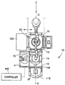
図1は、開示される発明における実施形態に基づく特徴を組み込む基板処理装置の一部の略図である。開示される発明における実施形態は図面を参照して説明されるが、開示される発明における実施形態は、その他の多くの形態でも実施可能である。また、あらゆる適切な大きさ、形、要素の種類、または素材も使用可能である。   FIG. 1 is a schematic view of a portion of a substrate processing apparatus incorporating features in accordance with an embodiment of the disclosed invention. While embodiments of the disclosed invention are described with reference to the drawings, embodiments of the disclosed invention can be practiced in many other forms. Also, any suitable size, shape, type of element, or material may be used.

図1に示される基板処理装置100は、開示される発明における実施形態に基づく特徴を有する代表的な基板処理器具である。この例において、処理装置100は、一般的なバッチ処理器具の構造を有するものとして示されている。その他の実施形態において、器具は、例えば基板のシングルステップ処理を実行するように構成され、もしくは、図2及び図3に図示されるように直線状またはデカルト配置に構成されるなど、あらゆる望ましい配置を有する。さらに別の実施形態において、基板処理装置は、分類装置、貯蔵装置、または計測装置等の、あらゆる望ましい種類の装置である。   The substrate processing apparatus 100 shown in FIG. 1 is a representative substrate processing tool having features in accordance with an embodiment of the disclosed invention. In this example, the processing apparatus 100 is shown as having the structure of a general batch processing tool. In other embodiments, the instrument is configured to perform single step processing of the substrate, or configured in any desired configuration, such as configured in a linear or Cartesian arrangement as illustrated in FIGS. 2 and 3 Have. In yet another embodiment, the substrate processing apparatus is any desired type of apparatus, such as a sorting apparatus, storage apparatus, or metrology apparatus.

装置100で処理された基板Sは、液晶ディスプレイパネル、ソーラーパネル、直径200mm、300mm、450mmのウエハ等の半導体ウエハ、もしくは、ブランクの基板等の、基板処理装置100によって処理されるのに適切なあらゆる形、大きさ、及び厚さを有するその他のあらゆる直径の基板を含むがそれに限定されないあらゆる適切な基板、または、ある寸法や特定の質量等の基板の特徴と類似する特徴を有する物体である。   The substrate S processed by the apparatus 100 is suitable for being processed by the substrate processing apparatus 100 such as a liquid crystal display panel, a solar panel, a semiconductor wafer such as a wafer with a diameter of 200 mm, 300 mm, or 450 mm, or a blank substrate. Any suitable substrate, including but not limited to substrates of any other diameter having any shape, size, and thickness, or an object having features similar to those of the substrate, such as certain dimensions and specific masses .

一つに実施形態において、装置100は一般的に、例えば真空室として機能するために備えられた、例えばミニ環境と、隣接する、制御された密閉環境を維持するために外部環境から密閉された、大気によって分離可能または密閉されたセクション110を形成するフロントセクション105とを有する。他の実施形態において、密閉環境セクションは、不活性ガス(例えばN2)または他のあらゆる環境的に密閉及び/または制御された大気を有する。   In one embodiment, the apparatus 100 is generally equipped, for example, to function as a vacuum chamber, eg, a mini environment, and an adjacent, sealed environment from an external environment to maintain a controlled and sealed environment. , And a front section 105 which forms a section 110 separable or sealed by the atmosphere. In another embodiment, the enclosed environment section comprises an inert gas (e.g., N2) or any other environmentally enclosed and / or controlled atmosphere.

フロントセクション105は一般的に、例えば一つ以上の基板保持カセット115と、フロントエンドロボット120とを有する。フロントセクション105はまた、例えば、アライナ162、またはそこに位置するバッファ等の、他のステーションまたはセクションを有する。セクション110は、一つ以上の処理モジュール125と、真空ロボットアーム130とを有する。処理モジュール125は、材料堆積、エッチング、ベーキング、研磨、イオン注入、洗浄等、あらゆる種類である。   The front section 105 generally comprises, for example, one or more substrate holding cassettes 115 and a front end robot 120. The front section 105 also has other stations or sections, such as, for example, an aligner 162 or a buffer located there. Section 110 includes one or more processing modules 125 and a vacuum robot arm 130. The processing module 125 may be any type, such as material deposition, etching, baking, polishing, ion implantation, cleaning, and the like.

当然のことながら、ロボット基準系のような望ましい基準座標系について、それぞれのモジュールの状態は、制御部170によって記録される。また、一つ以上のモジュールは、例えば基板上の基準を用いて規定された、望ましい配向にある基板を用いて基板Sを処理する。処理モジュールにおける基板の望ましい配向はまた、制御部170に記録される。密閉セクション110はまた、ロードロックと呼ばれる一つ以上の中間室を有する。図1に示される装置100は、ロードロック135及びロードロック140の二つのロードロックを有する。ロードロック135及び140は、基板Sがフロントセクション105と密閉セクション110の間を、密閉セクション110に存在するあらゆる環境的に密閉された大気の全体性を破らないように通過させるインターフェイスとして動作する。   Of course, for a desired reference coordinate system, such as a robot reference system, the state of each module is recorded by the controller 170. Also, one or more modules process the substrate S with the substrate in the desired orientation, as defined, for example, using a reference on the substrate. The desired orientation of the substrate in the processing module is also recorded in the controller 170. Sealed section 110 also has one or more intermediate chambers called load locks. The apparatus 100 shown in FIG. 1 has two load locks, a load lock 135 and a load lock 140. The load locks 135 and 140 act as an interface to allow the substrate S to pass between the front section 105 and the sealing section 110 without breaking the integrity of any environmentally sealed atmosphere present in the sealing section 110.

基板処理装置100は一般的に、基板処理装置100の動作を制御する制御部170を含む。一つの実施形態において、その発明全体を本願に包含するものである、2005年7月11日に出願された米国特許出願番号11/178615に記載されているように、制御部は、クラスタ化制御アーキテクチャの一部である。制御部170は、プロセッサ173とメモリ178とを有する。上記に加え、メモリ178は、オンザフライ基板偏心、及び不整合検出・修正のための方法を備えるプログラムを含む。メモリ178はさらに、処理モジュール及び装置のセクション105、110のその他の部分やステーションの温度及び/または圧力等の処理パラメータと、処理される基板Sの一時的な情報及び基板の計量情報と、オンザフライ基板偏心を規定する装置及び基板の位置データを適用するためのアルゴリズム等のプログラムとを含む。   The substrate processing apparatus 100 generally includes a control unit 170 that controls the operation of the substrate processing apparatus 100. In one embodiment, the controller controls clustering as described in US patent application Ser. No. 11 / 178,615, filed Jul. 11, 2005, the entire invention of which is incorporated herein by reference. It is part of the architecture. The control unit 170 has a processor 173 and a memory 178. In addition to the above, the memory 178 includes a program comprising methods for on-the-fly substrate eccentricity, and misalignment detection and correction. The memory 178 further comprises processing parameters such as temperature and / or pressure of the processing module and other sections of the sections 105, 110 of the processing unit and of the station and of the station, temporary information of the substrate S to be processed and weighing information of the substrate, on the fly. It includes a device that defines substrate eccentricity and a program such as an algorithm for applying substrate position data.

ATM(大気的)ロボットとも呼ばれるフロントエンドロボット120は、駆動セクション150と、一つ以上のアーム155とを含む。少なくとも一つのアーム155は、駆動セクション150に取り付けられる。少なくとも一つのアーム155は、一つ以上の基板Sを保持するための一つ以上のエンドエフェクタ165に結合された、リスト160に結合される。エンドエフェクタ165は、リスト160に回転可能に結合される。   The front end robot 120, also referred to as an ATM (atmospheric) robot, includes a drive section 150 and one or more arms 155. At least one arm 155 is attached to the drive section 150. At least one arm 155 is coupled to the wrist 160 coupled to one or more end effectors 165 for holding one or more substrates S. The end effector 165 is rotatably coupled to the wrist 160.

ATMロボット120は、フロントセクション105内のあらゆる位置に基板を搬送するように構成されている。例えば、ATMロボット120は、基板保持カセット115、ロードロック135、及びロードロック140の間で基板を搬送する。ATMロボット120はまた、基板Sをアライナ162との間で搬送する。駆動セクション150は、制御部170から指令を受け取り、それに応じて、ATMロボット120の、半径方向動作、円周方向動作、上昇動作、複合動作や、その他の動作を指示する。
真空ロボットアーム130は、セクション110の中央室175に取り付けられる。制御部170は、隙間180及び185を回転するように動作し、処理モジュール125、ロードロック135、及びロードロック140間で基板を搬送するための、真空ロボットアーム130の動作を調整する。真空ロボットアーム130は、駆動セクション190(下記に詳細が記載される)及び一つ以上のエンドエフェクタ195を含む。
The ATM robot 120 is configured to transport the substrate to any location within the front section 105. For example, the ATM robot 120 transports a substrate between the substrate holding cassette 115, the load lock 135, and the load lock 140. The ATM robot 120 also transports the substrate S to and from the aligner 162. The drive section 150 receives a command from the control unit 170, and in response, instructs the radial motion, circumferential motion, lifting motion, combined motion, and other motions of the ATM robot 120.
The vacuum robot arm 130 is attached to the central chamber 175 of the section 110. The controller 170 operates to rotate the gaps 180 and 185, and regulates the operation of the vacuum robot arm 130 for transporting the substrate between the processing module 125, the load lock 135, and the load lock 140. The vacuum robot arm 130 includes a drive section 190 (described in more detail below) and one or more end effectors 195.

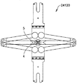
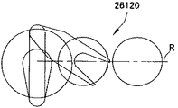
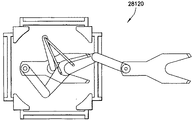
他の実施形態において、ATMロボット120及び真空ロボットアーム130は、スライド式アームロボット(例えば図1、7A−7B、9A−11C、13A、13C−14B、16−21を参照)、自由度2(例えば、ここに説明されるように二つの出力軸を有する同軸駆動部を用いる場合)、及び/または自由度3(ここに説明されるように三つの出力軸を有する三軸駆動部を用いる場合)(例えば図1−3を参照)を有するスカラ型ロボット、チョウ形の形状の、二つのアームを有するスカラ型ロボット(例えば図25、参照番号25120を参照)二つの前腕部とエンドエフェクタを持つ単一の上腕部を有するスカラ型ロボット(例えば図29、参照番号29120を参照)、不等長アームリンクスカラ型ロボット(例えば図26、参照番号26120を参照)、分岐したスカラ型ロボット(例えば図28、参照番号28120を参照)、関節アームロボット(例えば図23A、23B、参照番号23120を参照)、ロストモーションメカニズムを組み込んだ機械的スイッチを有するスカラ型搬送アーム(例えば図27、参照番号27120を参照)、カエル足型搬送装置(例えば図1を参照)、跳躍カエル型搬送(例えば図22、参照番号22120を参照)、または左右対称の搬送装置(例えば図24A−24D、参照番号24120を参照)を含むがそれに限定されない、搬送装置のあらゆる適切な種類のものである。   In another embodiment, the ATM robot 120 and the vacuum robot arm 130 are slide arm robots (see, eg, FIGS. 1, 7A-7B, 9A-11C, 13A, 13C-14B, 16-21), two degrees of freedom (see FIGS. For example, when using a coaxial drive with two output axes as described herein and / or when using a three axis drive with three output axes as described herein SCARA type robot (see, eg, FIGS. 1-3), SCARA type robot having two arms in the shape of a butterfly (eg, see FIG. 25, reference numeral 25120) having two forearms and an end effector A scalar robot (see, eg, FIG. 29, reference numeral 29120) having a single upper arm, an unequal-length arm link scalar robot (eg, FIG. 26). Reference numeral 26120), bifurcated scalar robot (see, for example, FIG. 28, reference numeral 28120), articulated arm robot (see, for example, FIGS. 23A and 23B, reference numeral 23120), mechanical switch incorporating a lost motion mechanism (See, for example, FIG. 27, reference numeral 27120), frog foot-type conveyance apparatus (for example, see FIG. 1), jumping frog-type conveyance (for example, FIG. 22, reference 22120), or left-right symmetry 24A-24D (see, for example, FIGS. 24A-24D, reference number 24120), but any suitable type of transport device.

当然のことながら、他の実施形態において、上記のアームは、アームが積み重ねられた一つ以上のエンドエフェクタ、または横に並べられた一つ以上のエンドエフェクタを含むようにするために、搬送基板をまとめるように構成されている。   It will be appreciated that in other embodiments, the arm may be a carrier substrate so that the arm includes one or more end effectors stacked or one or more end effectors side by side. It is configured to put together.

図2を参照すると、開示される実施形態における特徴に基づく、別の基板処理装置10の概略平面図が示されている。基板処理装置10は、細長い搬送室を通して搬送ロボット間を基板Sが通過する、直線状またはデカルト配置を有するように図示されている。ワークピース処理システム10、またはツールは一般的に、処理セクション13とインターフェイスセクション12を有する。ツール10のインターフェイス及び処理セクションは、互いに接続され、相互間のワークピースの搬送を可能とする。   Referring to FIG. 2, a schematic plan view of another substrate processing apparatus 10 is shown, in accordance with features of the disclosed embodiments. The substrate processing apparatus 10 is illustrated as having a linear or Cartesian arrangement, with the substrate S passing between transport robots through an elongated transport chamber. The workpiece processing system 10 or tool generally comprises a processing section 13 and an interface section 12. The interface and processing sections of the tool 10 are connected to one another to enable transfer of workpieces between one another.

ツールの処理セクション13は、実質的に図1と関連して上記に記載されたものと類似した、処理モジュールまたは室を有する。処理モジュールは、ワークピースが処理プロトコルに基づく望ましい処理モジュール間を搬送される、ワークピース搬送室16によって結合される。搬送室は、ワークピースを搬送室内、及び処理モジュール125へと移動可能な搬送ロボット20を有する。処理モジュール125及び搬送室は、大気的に隔離可能であり、搬送室内の大気を処理モジュールと同一、または、図1と関連して上記に記載されたものと実質的に類似する方法でワークピースが処理モジュール間を搬送されるのに適切なように維持するために、外部の大気から環境的に遮断された、制御された大気に保持可能である。   The processing section 13 of the tool comprises processing modules or chambers substantially similar to those described above in connection with FIG. The processing modules are coupled by a workpiece transfer chamber 16 in which the workpieces are transported between desired processing modules based on processing protocols. The transfer chamber has a transfer robot 20 capable of moving the workpiece to the transfer chamber and to the processing module 125. The processing module 125 and the transfer chamber may be atmospherically separable, and the atmosphere in the transfer chamber is the same as the processing module or the workpiece in a manner substantially similar to that described above in connection with FIG. Can be maintained in a controlled atmosphere that is environmentally shielded from the external atmosphere in order to maintain the proper to be transported between the processing modules.

ツールインターフェイスセクション12は、ツール処理セクション13とその制御された密閉大気、及びツールの外側との間に、ワークピースの取り付け/取り外しのためのインターフェイスを提供する。適切な環境インターフェイスセクションの例は、その発明全体を本願に包含するものである、2005年7月11日に出願された米国特許出願番号11/178836に開示されている。従って、ツールインターフェイスセクションは、ツールの外側で運搬装置によって搬送されるワークピースが、運搬装置からツールに取り外され、逆もまた同様に行われることを可能とする。   The tool interface section 12 provides an interface for attachment / removal of workpieces between the tool processing section 13 and its controlled enclosed atmosphere and the outside of the tool. An example of a suitable environmental interface section is disclosed in US patent application Ser. No. 11 / 178,836, filed Jul. 11, 2005, the entire invention of which is incorporated herein by reference. Thus, the tool interface section allows the workpiece carried by the carrier outside the tool to be removed from the carrier to the tool and vice versa.

搬送室は、例えば直線状に引き伸ばされた搬送室を形成するために、端と端を接続された搬送室モジュールから成る。従って、搬送室の長さは、搬送室モジュールを加えたり取り除いたりすることにより可変である。搬送室モジュールは、搬送室の隣接部分から望ましい搬送室モジュールを隔離可能な入口/出口ゲートバルブを有する。セクション12に類似するツールインターフェイスセクションは、ワークピースがツール内の望ましい位置に取り付けられまたは取り外されるように、直線状に引き伸ばされた搬送室に沿った、あらゆる望ましい位置に配置される。   The transfer chamber consists of a transfer chamber module connected end-to-end, for example to form a linearly stretched transfer chamber. Thus, the length of the transfer chamber can be varied by adding and removing transfer chamber modules. The transfer chamber module has an inlet / outlet gate valve that can isolate the desired transfer chamber module from adjacent portions of the transfer chamber. A tool interface section similar to section 12 may be placed at any desired location along the linearly stretched transfer chamber so that the workpiece is attached or removed at the desired location in the tool.

処理モジュールは、搬送室の長さに沿って分布される。処理モジュールは、搬送室の長さに対して角度を持った方向に積み重ねられる。搬送室モジュールは、処理モジュールから望ましい搬送室モジュールを隔離するための入口/出口ゲートバルブを有する。搬送システム20は、搬送室に沿って分布している。複数の搬送室モジュールは、モジュールに固定されたインターフェイス/マウントを有する一体可動アームと、搬送室に沿って、また、搬送室と処理モジュール間においてワークピースを直線状に保持及び移動可能な可動エンドエフェクタとを、それぞれ有する。   The processing modules are distributed along the length of the transfer chamber. The processing modules are stacked in a direction at an angle to the length of the transfer chamber. The transfer chamber module has an inlet / outlet gate valve to isolate the desired transfer chamber module from the processing module. The transfer system 20 is distributed along the transfer chamber. A plurality of transfer chamber modules are an integral movable arm having an interface / mount fixed to the modules, and a movable end capable of linearly holding and moving a workpiece along the transfer chamber and between the transfer chamber and the processing module Each has an effector.

異なる搬送室モジュール内の搬送アームは、直線状に分布された搬送システムの少なくとも一部を形成するたよう協働する。搬送システム、処理モジュール、処理セクション、インターフェイスセクション、及びツールの他のあらゆる部分の動作は、上記に記載の制御部170と実質的に類似する制御部400によって制御される。搬送室と搬送システムは、搬送室内に複数のワークピース移動通路が規定されるよう配置される。移動通路は、ワークピースの前進及び戻りのために、搬送室内において分極化または専用化される。搬送室はまた、搬送室の異なるセクションが異なる大気を保持することを可能とし、ワークピースが搬送室の異なる大気のセクション間を通過することを可能とする中間ロードロックを有する。   The transfer arms in the different transfer chamber modules cooperate to form at least a portion of the linearly distributed transfer system. The operation of the transport system, processing modules, processing sections, interface sections, and any other parts of the tool are controlled by a control unit 400 substantially similar to the control unit 170 described above. The transfer chamber and the transfer system are arranged such that a plurality of workpiece transfer paths are defined in the transfer chamber. The transfer path is polarized or dedicated in the transfer chamber for advancement and return of the workpiece. The transfer chamber also has an intermediate load lock that allows different sections of the transfer chamber to hold different atmospheres and allows workpieces to pass between the different atmospheric sections of the transfer chamber.

搬送室は、ワークピースが搬送室の望ましい位置から挿入/除去される、入口/出口ステーションを有する。例えば、入口/出口ステーションは、インターフェイスセクション12の反対端、または搬送室内の他の望ましい位置に配置される。搬送室の入口/出口ステーションは、搬送室の入口/出口ステーションを遠隔のツールインターフェイスセクション12に結合する、ワークピース高速移動通路と伝達を行う。高速移動通路は、搬送室16から独立し、隔離可能である。高速移動通路は、ワークピースがインターフェイスセクションと移動通路との間を移動するように、一つ以上のインターフェイスセクション12と伝達を行う。   The transfer chamber has an inlet / outlet station where workpieces are inserted / removed from the desired position of the transfer chamber. For example, the inlet / outlet station may be located at the opposite end of interface section 12 or at any other desired location within the transfer chamber. The transfer chamber inlet / outlet station communicates with the workpiece high speed travel path that couples the transfer chamber inlet / outlet station to the remote tool interface section 12. The high speed moving path is independent of the transfer chamber 16 and can be isolated. The fast travel path communicates with one or more interface sections 12 such that the workpiece travels between the interface section and the travel path.

ワークピースは、搬送室に作用することなく、ツールの高度のセクションに急速に配置され、処理された後、高速移動通路を通ってインターフェイスセクション12に戻され、結果的に仕掛品(WIP)の減少をもたらす。搬送室はまた、ワークピースが高速移動通路を移動することができるように高速移動通路と伝達を行う、中間入口/出口ステーションを有する。このことにより、その発明全体を本願に包含するものである、2006年5月26日に出願された米国特許出願番号11/442511に記載されているように、ワークピースが、処理の流れに作用することなく、処理の望ましい中間部に挿入または除去されることが可能となる。   The workpieces are rapidly placed in the advanced section of the tool, without processing in the transfer chamber, processed, and then returned to the interface section 12 through the high speed travel path, resulting in a WIP. Bring about a reduction. The transfer chamber also has an intermediate inlet / outlet station in communication with the high speed moving path so that the workpiece can move through the high speed moving path. This causes the work piece to act on the process flow, as described in US patent application Ser. No. 11 / 442,511, filed May 26, 2006, the entire invention of which is incorporated herein by reference. It is possible to insert or remove the desired intermediate part of the process without

インターフェイスセクション12は、間にロードロックを介さずに搬送室と直接結合する(図1に示される)。他の実施形態において、ロードロックはインターフェイスセクション12と搬送室との間に置かれる。図1に示されるインターフェイスセクションは、ロードポートLPに結合されたカセット115から搬送室16へワークピースを移動するためのワークピース搬送部15を有する。搬送部15は、インターフェイスセクション室14内に配置され、上記に記載の搬送部150と実質的に類似する。インターフェイスセクションはまた、アライナステーション、バッファステーション、計測ステーション、及びワークピースの他のあらゆる望ましい操作ステーション等の、ワークピースステーションAを含む。   The interface section 12 is directly coupled to the transfer chamber without the load lock in between (shown in FIG. 1). In another embodiment, a load lock is placed between the interface section 12 and the transfer chamber. The interface section shown in FIG. 1 has a workpiece transport 15 for moving workpieces from the cassette 115 coupled to the load port LP to the transport chamber 16. The transport 15 is disposed within the interface section chamber 14 and is substantially similar to the transport 150 described above. The interface section also includes a workpiece station A, such as an aligner station, a buffer station, a metrology station, and any other desired operating station for workpieces.

本発明の実施形態は、例えば、図3の搬送部800のように、真空ロボットまたは搬送部に関連して説明されるが、当然のことながら、開示される実施形態は、大気環境、制御された大気環境、及び/または真空環境を含むがそれに限定されない、あらゆる適切な環境で動作する、あらゆる適切な搬送または他の処理装置(例えばアライナ等)に用いることができる。一つの実施形態において、搬送部800は、例えば、複数のワークピースを独立して移動するための、独立して可動な複数のエンドエフェクタを有する。図3の搬送部800は、例えば、回転、伸張/後退、及び/またはリフト(例えばZ軸動作)に関するあらゆる適切な自由度を有する、例えば多関節リンクアームとして示されている。   Embodiments of the present invention will be described in the context of a vacuum robot or transport, as for example the transport 800 of FIG. 3, although it will be appreciated that the disclosed embodiments control the atmosphere environment, It may be used for any suitable transport or other processing apparatus (e.g. aligner etc) operating in any suitable environment, including but not limited to atmospheric environment and / or vacuum environment. In one embodiment, transport 800 includes a plurality of independently movable end effectors, eg, for independently moving a plurality of workpieces. The transport 800 of FIG. 3 is shown, for example, as an articulated link arm, having any suitable degree of freedom, for example, with respect to rotation, extension / retraction, and / or lift (eg, Z-axis motion).

また、当然のことながら、典型的な実施形態に基づく搬送部は、スライド式アームロボット(図1、7A−7B、9A−11C、13A、13C−14B、16−21を参照)、自由度2(ここに説明されるように、例えば二つの出力軸を有する同軸駆動部を用いる場合)、及び/または自由度3(ここに説明されるように三つの出力軸を有する三軸部を用いる場合)(例えば図1−3を参照)を有するスカラ型ロボット、チョウ形の形状の、二つのアームを有するスカラ型ロボット(例えば図25、参照番号25120を参照)二つの前腕部とエンドエフェクタを持つ単一の上腕部を有するスカラ型ロボット(例えば図29、参照番号29120を参照)、不等長アームリンクスカラ型ロボット(例えば図26、参照番号26120を参照)、分岐したスカラ型ロボット(例えば図28、参照番号28120を参照)、関節アームロボット(例えば図23A、23B、参照番号23120を参照)、ロストモーションメカニズムを組み込んだ機械的スイッチを有するスカラ型搬送アーム(例えば図27、参照番号27120を参照)、カエル足型搬送装置(例えば図1を参照)、跳躍カエル型搬送(例えば図22、参照番号22120を参照)、または左右対称の搬送装置(例えば図24A−24D、参照番号24120を参照)を含むがそれに限定されない、あらゆる適切な構造を備えることができる。   Also, as a matter of course, the transport unit based on the typical embodiment is a sliding arm robot (see FIGS. 1, 7A-7B, 9A-11C, 13A, 13C-14B, 16-21), 2 degrees of freedom. (As described herein, eg when using a coaxial drive with two output axes) and / or with three degrees of freedom (as described herein) with a triaxial section with three output axes SCARA type robot (see, eg, FIGS. 1-3), SCARA type robot having two arms in the shape of a butterfly (eg, see FIG. 25, reference numeral 25120) having two forearms and an end effector Scalar-type robot with a single upper arm (see, eg, FIG. 29, reference number 29120), unequal-length arm link scalar type robot (see, eg, FIG. 26, reference number 26120) , A branched SCARA robot (see, eg, FIG. 28, reference numeral 28120), an articulated arm robot (see, eg, FIGS. 23A, 23B, reference numeral 23120), a SCARA-type transfer arm having a mechanical switch incorporating a lost motion mechanism (See, eg, FIG. 27, ref. 27120), frog foot transport (see, eg, FIG. 1), jumping frog transport (see, eg, FIG. 22, ref. 22120), or a symmetric transport (eg, see FIG. Any suitable structure may be provided, including but not limited to 24A-24D (see reference numeral 24120).

典型的な実施形態における駆動システムが採用されるロボットアームの適切な例は、その発明全体を本願に包含するものである、米国特許第4666366号、第4730976号、第4909701号、第5431529号、第5577879号、第5720590号、第5899658号、第5180276号、第5647724号、第7578649号、及び「二重スカラアーム」と題された2005年6月9日付け米国特許出願番号11/148871、「機械的スイッチ機構を利用する複数の可動アームを有する基板搬送装置」と題された2008年5月8日付け米国特許出願番号12/117415、「複数の独立可動関節アームを伴う基板搬送装置」と題された2007年4月6日付け米国特許出願番号11/697390、「不等長リンクスカラアーム」と題された2005年7月11日付け米国特許出願番号11/179762に見られる。   Suitable examples of robot arms in which the drive system in the exemplary embodiment is adopted are the entire invention included in the present application, U.S. Pat. Nos. 4,666,366, 4,730,979, 4,909,701, 5,431,529, No. 5577879, No. 5720590, No. 5899,658, No. 5180276, No. 5647724, No. 7578649, and U.S. Patent Application Serial No. 11 / 148,877, dated June 9, 2005, entitled "Double Scalar Arm"; US Patent Application No. 12 / 117,415, filed May 8, 2008 entitled "Substrate Transport Device Having Multiple Movable Arms Using Mechanical Switch Mechanism", "Substrate Transport Device With Multiple Independent Movable Articulated Arms" U.S. Patent Application No. 11 / 697,390, dated April 6, 2007; Unequal-length dated July 11, 2005, entitled link SCARA arm "be found in US Patent Application No. 11/179762.

上記のように、他の実施形態において、上記アームは、アームが積み重ねられた一つ以上のエンドエフェクタ、または横に並べられた一つ以上のエンドエフェクタを含むようにするために、搬送基板をまとめるように構成されている。当然のことながら、ここに開示される実施形態に記載される搬送部は、例えば液晶ディスプレイパネルやソーラーパネル、または例えば約1キログラムから20キログラムを超えるペイロード、具体的には約15キログラムから20キログラムのペイロード、さらに具体的には約15キログラムのペイロード及び約20キログラムのペイロード等の他の重いペイロードのような、重い及び/または大きいペイロードを搬送するために構成された大容量ペイロード搬送部である。他の実施形態において、ペイロードは、約20キログラム以下、または約1キログラムである。   As mentioned above, in another embodiment, the arm includes a carrier substrate so that the arm includes one or more end effectors stacked or one or more end effectors side by side. It is configured to put together. It will be appreciated that the transport described in the embodiments disclosed herein may be, for example, a liquid crystal display panel or a solar panel, or a payload of, for example, about 1 kilogram to more than 20 kilograms, specifically about 15 kilograms to 20 kilograms. A large-capacity payload carrier configured to carry heavy and / or large payloads, such as a payload of one, and more specifically, another heavy payload such as a payload of about 15 kilograms and a payload of about 20 kilograms . In other embodiments, the payload is about 20 kilograms or less, or about 1 kilogram.

次に、図3〜5を参照すると、大容量搬送部は、上腕部810、前腕部820、及び少なくとも一つのエンドエフェクタ830を有する少なくとも一つのアーム800を含む。当然のことながら、開示される実施形態におけるいくつかの形態はアーム800について説明されるが、上記に記載されているようなその他の適切なアームは、ここに記載される駆動システムに取り付けられ、駆動システムによって駆動する。エンドエフェクタ830は前腕部820に回転可能に結合され、前腕部820は上腕部810に回転可能に結合される。上腕部810は、例えば搬送装置の駆動セクション840に回転可能に取り付けられる。   Referring now to FIGS. 3-5, the mass transport includes at least one arm 800 having an upper arm 810, a forearm 820, and at least one end effector 830. It should be appreciated that although some forms in the disclosed embodiment are described for the arm 800, other suitable arms as described above are attached to the drive system described herein, Drive by drive system. The end effector 830 is rotatably coupled to the forearm 820, and the forearm 820 is rotatably coupled to the upper arm 810. Upper arm 810 is rotatably mounted, for example, to drive section 840 of the transport apparatus.

典型とする目的においてのみ、駆動セクション840は、駆動軸システムがあらゆる適切な下図の同軸駆動軸またはスピンドル(図5に示される同軸駆動システムは、例とする目的のための二つの同軸シャフトを有し、他の実施形態においてはこれよりも多いまたは少ないシャフトが用いられる)を含む、同軸駆動システムを含む。駆動システム840は、アームが作動する搬送室の内部や他の基板処理環境のような密閉制御環境SEを、制御環境SEの外部にあり駆動セクションの筐体840H内にある大気的または外部環境ATMから密閉隔離することができるように、環境フランジ595に密閉して取り付けられる。その結果、駆動筐体840H内の環境は、下記にさらに記載されるように、大気的である。   For exemplary purposes only, drive section 840 may have any suitable lower coaxial drive shaft or spindle (the coaxial drive system shown in FIG. 5 has two coaxial shafts for exemplary purposes). And, in other embodiments, more or less shafts are used). Drive system 840 may be a closed control environment SE, such as an interior of a transfer chamber in which the arm operates, or other substrate processing environment, outside the control environment SE, in an enclosure 840H of the drive section, in an atmospheric or external environment ATM. To the environmental flange 595 so that it can be hermetically isolated. As a result, the environment within drive housing 840H is atmospheric, as described further below.

駆動セクション840は、ハーモニック駆動セクションとして構成される。例えば、駆動セクション840は、あらゆる適切な数のハーモニック駆動モータを含む。駆動セクション840は、駆動セクション840がインストールされる処理モジュールを修正することなく、実質的に駆動セクション840が非ハーモニック型駆動セクションと互換性があるような、あらゆる適切な形や大きさである。一つの実施形態において、図5に示される駆動セクション840は、外部軸211を駆動するための一方のモータ及び内部軸212を駆動するための他方のモータである、二つのハーモニック駆動モータ208、209を含む。他の実施形態において、駆動セクションは、例えば同軸駆動システム内のあらゆる適切な数の駆動軸に対応して、あらゆる適切な数のハーモニック駆動モータを含むことに留意されたい。 Drive section 840 is configured as a harmonic drive section. For example, drive section 840 includes any suitable number of harmonic drive motors. The drive section 840 may be of any suitable shape or size such that the drive section 840 is substantially compatible with the non- harmonic drive section without modifying the processing module in which the drive section 840 is installed. In one embodiment, the drive section 840 shown in FIG. 5 is two harmonic drive motors 208, 209, one motor for driving the outer shaft 211 and the other motor for driving the inner shaft 212. including. It should be noted that in other embodiments, the drive section comprises any suitable number of harmonic drive motors, for example corresponding to any suitable number of drive axes in a coaxial drive system.

ハーモニック駆動モータ208、209は、一般的に磁性流体シール500と呼ばれる磁性流体シールの構成部品が、少なくとも部分的に、ロボットアームの望ましい回転Tと伸張Rの動作の間に十分な安定性と隙間とを有するハーモニック駆動モータ208、209によって中心に置かれ支持されるために、大容量出力ベアリングを有する。磁性流体シール500は、下記に記載されるように、実質的に同心の同軸シールを形成するいくつかの部品を含むことに留意されたい。 The harmonic drive motor 208, 209 is a magnetic fluid seal component commonly referred to as the magnetic fluid seal 500, at least partially sufficient stability and clearance between the desired rotation T and extension R motion of the robot arm. And has a high capacity output bearing to be centered and supported by the harmonic drive motor 208,209. It should be noted that the magnetic fluid seal 500 includes several parts that form a substantially concentric coaxial seal, as described below.

この例において、駆動セクション840は、二つの駆動モータ208と209を、その発明全体を本願に包含するものである、米国特許第6845250号、第5899658号、第5813823号、及び第5720590号に記載に方法に類似した方法で、連続して(例えば、共通の回転軸上に直列してまたは一方の上に他方が積み重ねられ、もしくは他の実施形態においては、モータは互いにネストされ、または互いに相殺され適切な搬送装置を通して同軸シャフト組立部品のそれぞれの軸に取り付けられる)格納する筐体840Hを含む。モータは、最上部のモータ208が貫通孔を有し(例えば、モータ回転子は外部軸に取り付けられる)、下層のモータ209(または図6に示されるように三つ以上の同軸シャフトの場合には複数の下層モータ)が、貫通孔を通って筐体840Hの駆動エンドに達する駆動軸212を有するように構成されている。   In this example, drive section 840 is described in US Pat. Nos. 6,845,250, 5,899,658, 5,813,823, and 5,720,590, the entire invention of which is incorporated herein by reference. In a manner analogous to that in series (eg, one on top of another in series or on top of a common rotational axis, or in another embodiment, the motors are nested within one another or offset from one another) Housing 840 H) which is attached to the respective axes of the coaxial shaft assembly through a suitable transport device. The motor is such that the top motor 208 has a through hole (eg, the motor rotor is attached to the outer shaft) and the lower motor 209 (or in the case of three or more coaxial shafts as shown in FIG. 6) Are configured to have the drive shaft 212 reaching the drive end of the housing 840H through the through holes.

磁性流体シール500は、下記にさらに記載されるように、同軸駆動軸組立部品内のそれぞれの駆動軸を密閉することを許容可能である。最内部の駆動軸712もまた、ワイヤまたは他のあらゆる適切なアイテムの、例えば駆動部840に取り付けられたアーム800のようなアーム組立部品への、同軸駆動組立部品内の通過を許容するための中空構造を有する(例えば、駆動軸の中心に沿って長手方向に穴を有する)ことに留意されたい。アーム800が動作する制御環境を駆動部840の内部から密閉するために、(大気圧環境内で動作する)駆動部840は、アームが例えばワイヤを傷つけることなく回転することを可能とする、隔離ワイヤフィードスルー590を含む。ワイヤフィードスルーの一つの適切な例は、その発明全体を本願に包含するものである、米国特許第6265803号に見られる。   The magnetic fluid seal 500 is acceptable to seal the respective drive shaft in the coaxial drive shaft assembly, as described further below. The innermost drive shaft 712 is also for allowing passage of the wire or any other suitable item within the coaxial drive assembly, for example to an arm assembly such as the arm 800 attached to the drive 840. It should be noted that it has a hollow structure (e.g. having a hole longitudinally along the center of the drive shaft). In order to seal the controlled environment in which the arm 800 operates from the inside of the drive 840, the drive 840 (operating in the atmospheric pressure environment) allows the arm to rotate, for example without damaging the wires, isolation Wire feedthrough 590 is included. One suitable example of a wire feedthrough is found in US Pat. No. 6,265,803, the entire invention of which is incorporated herein.

次に、図3及び5を参照すると、二つのモータ208、209は、アームが少なくとも自由度2(例えば、図3に示される、一般的にT動作と呼ばれる、例えばZ軸の回りの回転、及び、一般的にR動作と呼ばれる、例えばX−Y面の伸張)を有するように、アーム800の動作を可能とする。他の実施形態において、駆動セクション840はまた、例えば、基板搬送面または基板保持ステーションに設置されたアーム800及びエンドエフェクタ830を上下に動かすために、駆動セクションが矢印210Aの方向に移動することを可能とするZ軸モータ210を含む。当然のことながら、Z軸モータ210が用いられる場合、ロボットアーム駆動システムは、例えば駆動システムの筐体840Hと環境フランジ595との間の、あらゆる適切な可撓接続を含む。一つの実施形態において、可撓接続はベローズ670であるが、他の実施形態においては、あらゆる適切な接続が用いられる。   Next, referring to FIGS. 3 and 5, the two motors 208, 209 have at least two degrees of freedom in the arms (e.g., generally referred to as T motion, as shown in FIG. 3, for example rotation about the Z axis, And enables the motion of the arm 800 to have an extension, generally referred to as an R operation, for example an X-Y plane. In other embodiments, the drive section 840 also moves the drive section in the direction of arrow 210A, for example, to move the arm 800 and the end effector 830 installed at the substrate transfer surface or the substrate holding station up and down. A Z-axis motor 210 is included to allow. Of course, where a Z-axis motor 210 is used, the robotic arm drive system includes any suitable flexible connection, for example, between the drive system housing 840H and the environmental flange 595. In one embodiment, the flexible connection is a bellows 670, but in other embodiments any suitable connection is used.

同軸シャフトまたはスピンドルが二つの駆動軸211、212を有するように図示されているものの、他の実施形態においては、スピンドルは二つ以上または以下の駆動軸を有する。さらに他の実施形態において、駆動軸はあらゆる適切な構造を有する。この例において、同軸駆動軸の外部軸211は、上腕部810に適切に結合され、内部軸212は前腕部820に適切に結合される。この例において、エンドエフェクタ830は“スレーブ”構造において動作するが、他の実施形態においては(例えば図6を参照)、エンドエフェクタ830を動作するために追加の駆動軸が駆動ユニットに含まれる。当然のことながら、駆動軸は、ハーモニック駆動システムに(上記に記載のような)異なるアーム構造を取り付けるために共通のアームインターフェイスを提供するように構成される。 Although a coaxial shaft or spindle is illustrated as having two drive shafts 211, 212, in other embodiments, the spindle has more or less than two drive shafts. In still other embodiments, the drive shaft has any suitable structure. In this example, the outer shaft 211 of the coaxial drive shaft is suitably coupled to the upper arm 810 and the inner shaft 212 is suitably coupled to the forearm 820. In this example, the end effector 830 operates in a "slave" configuration, but in other embodiments (see, eg, FIG. 6), an additional drive axis is included in the drive unit to operate the end effector 830. It will be appreciated that the drive shaft is configured to provide a common arm interface for attaching different arm structures (as described above) to the harmonic drive system.

上記のように、モータ208、209はそれぞれ、モータが互いに直列に配置されるように同心状に積み重ねられた構造で、筐体840H内に取り付けられる。モータは、あらゆる適切な交流(AC)モータまたは直流(DC)モータ、例えばサーボモータ、ステッピングモータ、AC誘導モータ、DCブラシレスモータ、DCコアレスモータ、または他のあらゆる適切なモータである。この典型的な実施形態において、モータ208は、筐体840H内に固定して取り付けられた固定子208Sと、ベアリング208Bによって等あらゆる適切な方法で筐体840H内に回転可能に取り付けられた回転子208Rとを含む。カム部材、または造波機208Wと呼ばれるものは、回転子208Rと調和して回転するために適切なあらゆる方法で回転子208Rに取り付けられる。   As noted above, the motors 208, 209 are each mounted within the housing 840H in a concentrically stacked configuration such that the motors are arranged in series with one another. The motor is any suitable alternating current (AC) motor or direct current (DC) motor, such as a servo motor, a stepping motor, an AC induction motor, a DC brushless motor, a DC coreless motor, or any other suitable motor. In this exemplary embodiment, motor 208 includes a stator 208S fixedly mounted within housing 840H and a rotor rotatably mounted within housing 840H in any suitable manner such as by bearings 208B. And 208R. The cam members, or so called wave makers 208W, are attached to the rotor 208R in any suitable manner to rotate in unison with the rotor 208R.

造波機208Wは、一般的に楕円形のカムの外周に組み込まれた適切なボールベアリング208WBを含む。ベアリングの内部配線管はカムに固定され、外部配線管はボールベアリング208WBを介して弾性変形にさらされる。第一のスプライン部材208Fは、筐体840Hに回転可能に固定されるために適切なあらゆる方法で筐体840H内に固定して支持される。第一のスプライン部材は、実質的にねじれて固い構造を形成する、実質的に固い部分208F及び実質的に柔軟な部分208FFを有する。スプライン部材208Fは、カムの作用下においては局所的に柔軟であるが、シャフト組立部品の中心線の位置をアームのR、T動作の範囲以下(例えば図3のZ軸)に実質的に調整するために望ましい全身硬直を提供し、従って、磁性流体シールにおける望ましい隙間を維持する。第一のスプライン部材208Fは、実質的に固い部分208FRを通して筐体に取り付けられる。   Wave maker 208W includes a suitable ball bearing 208WB incorporated into the outer periphery of the generally oval cam. The inner raceway of the bearing is fixed to the cam and the outer raceway is exposed to elastic deformation via the ball bearing 208WB. The first spline member 208F is fixedly supported within the housing 840H in any suitable manner to be rotatably fixed to the housing 840H. The first spline member has a substantially rigid portion 208F and a substantially flexible portion 208FF that form a substantially torsionally rigid structure. The spline member 208F is locally flexible under the action of the cam, but it adjusts the position of the centerline of the shaft assembly substantially below the range of R, T motion of the arm (e.g., the Z axis in FIG. 3) To provide the desired overall stiffness to maintain the desired clearance in the magnetic fluid seal. The first spline member 208F is attached to the housing through the substantially rigid portion 208FR.

第二のスプライン部材208Cは、それぞれ同軸シャフトに取り付けられる。ここで、第二のスプライン部材208Cは、外部軸211と第二のスプライン部材208Cとが一体として回転するために適切なあらゆる方法で外部軸211に結合される。第二のスプライン部材208Cは、実質的に固い環状である。第一のスプライン部材208Fは、第一のスプライン部材208Fの柔軟な部分208FFの外周の周りに形成されたギアの歯を有する。第二のスプライン部材208Cも、第二のスプライン部材208Cの内周の周りに形成された歯を有する。回転子208Rが回転すると、第一のスプライン部材208Fのギアの歯が、第二のスプライン部材208Cのギアの歯とかみ合って連動するように、造波機はカムを用いて第一のスプライン部材208Fの柔軟な部分208FFを局所的に屈折させる。しかしながら、造波機のカムの楕円形の形状により、造波機楕円の主要な軸と連携している第一のスプライン部材208Fの歯のみが第二のスプライン部材208Cの歯と連動し、造波機楕円のその他の軸に沿った第一のスプライン部材208Fの歯は第二のスプライン部材208Cのギアの歯から実質的に完全に遊離している。   The second spline members 208C are each attached to the coaxial shaft. Here, the second spline member 208C is coupled to the outer shaft 211 in any suitable manner for the outer shaft 211 and the second spline member 208C to rotate together. The second spline member 208C is substantially rigid and annular. The first spline member 208F has gear teeth formed around the periphery of the flexible portion 208FF of the first spline member 208F. The second spline member 208C also has teeth formed around the inner periphery of the second spline member 208C. As the rotor 208R rotates, the wave making machine uses the cam to engage the first spline member so that the gear teeth of the first spline member 208F engage and interlock with the gear teeth of the second spline member 208C. Locally deflect the flexible portion 208FF of 208F. However, due to the oval shape of the wave maker's cam, only the teeth of the first spline member 208F which are associated with the main axis of the wave creator oval are engaged with the teeth of the second spline member 208C The teeth of the first spline member 208F along the other axis of the wave ellipse are substantially completely free of the gear teeth of the second spline member 208C.

第一のスプライン部材208Fの歯は、第二のスプライン部材208Cの歯よりも少なく(もしくは逆もまた同様)、駆動軸211の回転をもたらす第一のスプライン部材208Fと関連して、第二のスプライン部材208Cの回転動作をもたらす。第一のスプライン部材のねじれた固さ及び/またはハーモニック駆動部によって提供された減速は、駆動システムに取り付けられたロボットアームの結合を駆動するための増加したトルクプロファイルを許容する。当然のことながら、駆動軸211は、あらゆる適切な方法で矢印210Aの方向の軸方向に支持される。一つの実施形態において、駆動軸211は、ハーモニック駆動208によって矢印210Aの方向に支持される。他の実施形態において、駆動軸211は、あらゆる適切なベアリングによって矢印210Aの方向に支持される。さらに他の実施形態において、駆動軸211は、ハーモニック駆動208及び適切なベアリングの組み合わせによって矢印210Aの方向に支持される。 The teeth of the first spline member 208F are less than the teeth of the second spline member 208C (or vice versa) and, in conjunction with the first spline member 208F that causes the rotation of the drive shaft 211, The rotational movement of the spline member 208C is brought about. The torsional stiffness of the first spline member and / or the deceleration provided by the harmonic drive allow for an increased torque profile for driving the coupling of a robotic arm attached to the drive system. It will be appreciated that the drive shaft 211 is supported axially in the direction of arrow 210A in any suitable manner. In one embodiment, drive shaft 211 is supported by harmonic drive 208 in the direction of arrow 210A. In other embodiments, drive shaft 211 is supported in the direction of arrow 210A by any suitable bearing. In yet another embodiment, drive shaft 211 is supported in the direction of arrow 210A by a combination of harmonic drive 208 and appropriate bearings.

モータ209は、モータ208に関して上記の、固定子208S、回転子208R、造波機208W、第一のスプライン部材208F、及び第二のスプライン部材208Cにそれぞれ類似する、固定子209S、回転子209R、造波機209W、第一のスプライン部材209F、及び第二のスプライン部材209Cをモータ209も含む点で、形状と動作においてモータ208と実質的に類似する。内部駆動軸212は、内部駆動軸212と第二のスプライン部材209Cが一体として回転するために適切なあらゆる方法で第二のスプライン部材209Cに固定して結合される。上記に記載された方法と実質的に類似した方法で、駆動軸212は、あらゆる適切な方法で矢印210Aの方向に軸方向に支持される。一つの実施形態において、駆動軸212は、ハーモニック駆動部209によって矢印210Aの方向に軸方向に支持される。他の実施形態において、駆動軸212は、あらゆる適切なベアリングによって矢印210Aの方向に支持される。さらに他の実施形態において、駆動軸212は、ハーモニック駆動部209及び適切なベアリングの組み合わせによって矢印210Aの方向に支持される。 The motor 209 is similar to the stator 208S, the rotor 208R, the wave generator 208W, the first spline member 208F, and the second spline member 208C described above with respect to the motor 208, the stator 209S, the rotor 209R, It is substantially similar in shape and operation to the motor 208 in that it also includes the wave generator 209W, the first spline member 209F, and the second spline member 209C. The inner drive shaft 212 is fixedly coupled to the second spline member 209C in any suitable manner for the inner drive shaft 212 and the second spline member 209C to rotate together. In a manner substantially similar to that described above, drive shaft 212 is axially supported in the direction of arrow 210A in any suitable manner. In one embodiment, drive shaft 212 is axially supported by harmonic drive 209 in the direction of arrow 210A. In other embodiments, drive shaft 212 is supported in the direction of arrow 210A by any suitable bearing. In yet another embodiment, drive shaft 212 is supported in the direction of arrow 210A by a combination of harmonic drive 209 and appropriate bearings.

当然のことながら、互いに、またシャフト組立部品及び筐体を制御環境SEから隔離する磁性流体シールに対する内部及び外部駆動軸211、212の同心性は、磁性流体シール500を維持するように(例えば、ハーモニック駆動部208、209は、一つ以上の磁性流体シールが一つ以上のシャフト及び筐体の間に配置されるように、それぞれの駆動軸を互いに、及び筐体の少なくとも一部に対して実質的に同心状に配置する)、シャフトと筐体の一部との間の隙間を制御するためのハーモニック駆動部209、209の第一及び第二のスプライン部材208F、208C、209F、209Cのそれぞれのギア間の相互作用を通して維持される。 It will be appreciated that the concentricity of the inner and outer drive shafts 211, 212 with respect to the magnetic fluid seal that isolates one another and the shaft assembly and the housing from the control environment SE maintain the magnetic fluid seal 500 (e.g. The harmonic drives 208, 209 have their respective drive axes relative to one another and to at least a portion of the housing such that one or more magnetic fluid seals are disposed between the one or more shafts and the housing. Of the first and second spline members 208F, 208C, 209F, 209C of the harmonic drives 209, 209 for controlling the gap between the shaft and part of the housing (arranged substantially concentrically) It is maintained through the interaction between each gear.

例えば、上記のように、それぞれモータ208、209の第二のスプライン部材208C、209Cは、実質的に固い環状である。対応する第二のスプライン部材208C、209Cに対する第一のスプライン部材208F、209Fの変形(これによって歯がかみ合わさる)は、対応する第二のスプライン部材208C、209Cに、互いに及び筐体840Hの少なくとも一部に対して実質的に同心状に結合されたシャフト211、212を保持する。当然のことながら、他の実施形態において、ベアリングはハーモニック駆動部と連動して、駆動軸の間の実質的な同心性を維持するために、例えば駆動軸の間または駆動システム内の他のあらゆる適切な位置に配置される。 For example, as described above, the second spline members 208C, 209C of the motors 208, 209, respectively, are substantially rigid and annular. The deformations of the first spline members 208F, 209F with respect to the corresponding second spline members 208C, 209C, whereby the teeth engage, correspond to each other and to at least one of the housings 840H in the corresponding second spline members 208C, 209C. It holds the shafts 211, 212 connected substantially concentrically with respect to a part. Of course, in other embodiments, the bearings work in conjunction with the harmonic drive to maintain substantial concentricity between the drive axes, eg, between the drive axes or any other in the drive system Be placed in the proper position.

上記のように、ハーモニック駆動部208、209は、アーム800(駆動システム840の駆動軸に取り付けられる)のようなロボットアームが駆動システムの筐体840H及び他の外部環境内の大気圧環境から動作する、密閉制御環境を隔離するための、駆動システム840内での実質的に同心の同軸磁性流体シール500(または他のあらゆる適切なシール)の使用を許容する。ハーモニック駆動システムは、磁性流体シールが配置される隙間を厳重に制御するために、実質的に駆動軸のぶれを最小限にするように構成されている。さらに図5を参照し、第一の磁性流体シール500Aは、例えば第二のスプライン部材208Cと筐体840Hの一部との間に配置される。 As noted above, the harmonic drives 208, 209 operate such that a robotic arm such as the arm 800 (attached to the drive shaft of the drive system 840) operates from the atmospheric pressure environment within the drive system housing 840H and other external environments. Allow the use of a substantially concentric coaxial magnetic fluid seal 500 (or any other suitable seal) within drive system 840 to isolate the closed control environment. The harmonic drive system is configured to substantially minimize drive shaft deflection to tightly control the gap in which the magnetic fluid seal is located. Still referring to FIG. 5, the first magnetic fluid seal 500A is disposed, for example, between the second spline member 208C and a portion of the housing 840H.

一つの例において、ハーモニック駆動部208の第二のスプライン部材208Cは、第一の磁性流体シール500Aを少なくとも部分的に維持するための磁性流体シール面208CSを含む。第二の磁性流体シール500Bは、外部駆動軸211と内部駆動軸212との間に配置される。そのようにして、ハーモニック駆動部208と筐体840Hとの間、及び外部軸211と内部軸212との間に、駆動システム840内の大気環境から、密閉制御環境を駆動システム840の出力側に密閉して隔離するための大気的バリアが形成される。当然のことながら、この実施形態において、ハーモニック駆動部208、209の出力部は、例えば磁性流体シール500A、500Bによって、ハーモニック駆動部208、209の入力部から密閉して隔離されている。反対に、上記のように、磁性流体シールは(少なくとも部分的に)出力部208CS、またはハーモニック駆動部の出力部に従属する部分(例えば内部軸212の外面)に従属する。駆動システム840に関連して二つの磁性流体シール500A、500Bが記載されているが、他の実施形態においては、二つ以上または以下の磁性流体シールが、大気環境から実質的に密閉制御環境を密閉するために筐体840H内のあらゆる適切な位置に配置されることに留意されたい。 In one example, the second spline member 208C of the harmonic drive 208 includes a magnetic fluid sealing surface 208CS for at least partially maintaining the first magnetic fluid seal 500A. The second magnetic fluid seal 500 B is disposed between the outer drive shaft 211 and the inner drive shaft 212. As such, from the atmospheric environment in the drive system 840 between the harmonic drive unit 208 and the housing 840 H, and between the outer shaft 211 and the inner shaft 212, the closed control environment is on the output side of the drive system 840. An atmospheric barrier is formed to seal and isolate. Of course, in this embodiment, the output of the harmonic drive unit 208 and 209, for example, a magnetic fluid seal 500A, the 500B, are isolated hermetically from the input unit of the harmonic drive unit 208, 209. Conversely, as mentioned above, the magnetic fluid seal is (at least partially) dependent on the output 208CS, or a portion subordinate to the output of the harmonic drive (e.g. the outer surface of the inner shaft 212). Although two magnetic fluid seals 500A, 500B are described in connection with drive system 840, in other embodiments, two or more or less magnetic fluid seals provide a substantially closed control environment from the atmospheric environment. It should be noted that it may be placed in any suitable position within the housing 840H to seal.

磁性流体シール500A、500Bは、筐体840H内で駆動システム840によって生成された微粒子が密閉制御環境に漏れ出ないように、制御密閉環境の腐食性材料が筐体840H内に入らないように、かつ真空で用いられた際に、磁性流体シール500は大気バリアを提供するため、例えば筐体840H内に配置された駆動システム840の内部コンポーネントが真空に準拠している必要がないように、密閉制御環境及び大気環境が相互作用することができる、筐体840Hのインターフェイスに備えられる。また、駆動システム840の磁性流体シール500A、500Bの配置は典型であるだけであり、他の実施形態においては、磁性流体シールは他のあらゆる適切な配置及び構造を有することにも留意されたい。   The magnetic fluid seals 500A, 500B prevent the corrosive material of the controlled sealing environment from entering the housing 840H, so that particulates generated by the drive system 840 within the housing 840H do not leak into the sealing control environment. And, when used in a vacuum, the magnetic fluid seal 500 provides an atmospheric barrier, for example, so that the internal components of the drive system 840 located in the housing 840H do not have to be vacuum compliant. A control environment and an atmospheric environment are provided at the interface of housing 840H, which can interact. It should also be noted that the arrangement of the magnetic fluid seals 500A, 500B of the drive system 840 is only exemplary, and in other embodiments, the magnetic fluid seals have any other suitable arrangement and configuration.

アーム800などのロボットアームが正確に配置されるように、一つ以上の適切な絶対値または相対値エンコーダ208E、209E、もしくは他のあらゆる適切な位置検知装置は、それぞれハーモニックドライブ(登録商標)208、209の回転を検知するために、少なくとも部分的に筐体内におけるあらゆる適切な位置に配置される。一つ以上のエンコーダ変換ユニット208EC、209ECは、例えばそれぞれエンコーダ208E、209Eからの信号を変換するため、例えば、制御部170のようなあらゆる適切な制御部による使用のために、筐体840H内に配置される。筐体840Hは、エンコーダ208E、209E、及び/または固定子208S、209S、または筐体840H内に配置された他のあらゆる適切な電気部品への電気的接続を可能とするための、一つ以上のワイヤフィードスルー650を有する。当然のことながら、エンコーダ、エンコーダ変換ユニット、及びフィードスルーの配置は典型であるだけであり、他の実施形態においては、エンコーダ、エンコーダ変換ユニット、及びフィードスルーはあらゆる適切な配置及び構造を有する。 One or more suitable absolute or relative value encoders 208E, 209E, or any other suitable position sensing device may each be a HarmonicDrive® 208 so that a robotic arm such as the arm 800 may be accurately positioned. , 209 to be at least partially positioned at any suitable position within the housing. One or more of the encoder conversion units 208EC, 209EC may, for example, convert the signals from the encoders 208E, 209E, for example, in the housing 840H for use by any suitable controller, such as the controller 170, for example. Be placed. Housing 840H may be one or more for enabling electrical connection to encoders 208E, 209E and / or stators 208S, 209S, or any other suitable electrical components disposed in housing 840H. Wire feed through 650. Of course, the arrangement of encoders, encoder conversion units, and feedthroughs is only exemplary, and in other embodiments the encoders, encoder conversion units, and feedthroughs have any suitable arrangement and configuration.

開示される発明の実施形態を包含する別のハーモニック駆動システムが、図6に示されている。駆動セクション840’は、各モータがそれぞれ内部軸712、中間軸713、及び外部軸711を駆動する、三つのハーモニック駆動モータ708、709、710を有する三つの軸または三軸シャフト組立部品を含む。この例において、それぞれのアームリンクが独立して回転可能なように、同軸駆動軸の外部軸711は例えばアーム800の上腕部810に適切に結合され、内部軸712はエンドエフェクタ830に適切に結合され、中間軸は前腕部820に適切に結合される。各モータ708、709、710は、すべてそれぞれに対応する固定子208S、209S、回転子208R、209R、造波機208W、209W、第一のスプライン部材208F、209F、第二のスプライン部材208C、209Cと実質的に類似する、固定子708S、709S、710S、回転子708R、709R、710R、造波機708W、709W、710W、第一のスプライン部材708F、709F、710F、第二のスプライン部材708C、709C、710Cを含む点で、上記のモータ208、209に実質的に類似している。内部軸712は、シャフト212に関連して上記に記載の方法と類似した方法で、ワイヤまたは他のあらゆる適切な物体のための実質的に密閉されたフィードスルーを、例えばロボットアーム800の一つ以上のリンクに入れることを可能とするために中空である。 Another harmonic drive system, including embodiments of the disclosed invention, is shown in FIG. The drive section 840 'includes a three axis or three axis shaft assembly with three harmonic drive motors 708, 709, 710, each motor driving an inner shaft 712, an intermediate shaft 713 and an outer shaft 711 respectively. In this example, the outer shaft 711 of the coaxial drive shaft is suitably coupled to, for example, the upper arm 810 of the arm 800, and the inner shaft 712 is suitably coupled to the end effector 830, such that each arm link is independently rotatable. And the intermediate shaft is properly coupled to the forearm 820. The motors 708, 709, 710 respectively correspond to the stators 208S, 209S, the rotors 208R, 209R, the wave generators 208W, 209W, the first spline members 208F, 209F, the second spline members 208C, 209C. , Stators 708 S, 709 S, 710 S, rotors 708 R, 709 R, 710 R, wave generators 708 W, 709 W, 710 W, first spline members 708 F, 709 F, 710 F, second spline members 708 C, It is substantially similar to the motors 208, 209 described above in that they include 709C, 710C. The inner shaft 712 may be substantially closed feedthrough for a wire or any other suitable object, such as one of the robotic arms 800, in a manner similar to that described above in connection with the shaft 212. It is hollow to allow it to be put into the above link.

この実施形態において、図6に関連した上記に記載の方法と類似した方法で、モータ708は外部軸711を駆動し、モータ709は内部軸712を駆動し、モータ710は中間軸を駆動する。上記のように、互いの、及び/または筐体840H’に対するシャフトの同心性は、ハーモニック駆動モータ708、709、710によって実質的に維持される。例えば、上記のように、第一及び第二のスプライン部材708F、708C、709F、709C、710F、710C間のそれぞれの相互作用は、磁性流体シール500が維持されるように(例えば、ハーモニック駆動部708、709、710は、一つ以上の磁性流体シールがシャフト間、及び一つ以上のシャフトと筐体の間に配置されるように、それぞれの駆動軸を互いに、及び少なくとも筐体の一部に対して実質的に同心状に配置する)、シャフトと筐体の一部との間の隙間を制御する。さらに、上記のように、他の実施形態において、適切なベアリングは、ハーモニック駆動モータ708、709、710とともに、一つ以上のシャフト間の、及び/または筐体の一部と一つ以上のシャフトとの間の実質的な同心性を維持するために駆動軸の間、または筐体840H’内の他のあらゆる適切な位置に配置される。 In this embodiment, the motor 708 drives the outer shaft 711, the motor 709 drives the inner shaft 712, and the motor 710 drives the intermediate shaft, in a manner similar to the method described above in connection with FIG. As noted above, the concentricity of the shafts with each other and / or with respect to the housing 840H 'is substantially maintained by the harmonic drive motors 708, 709, 710. For example, as described above, the respective interactions between the first and second spline members 708F, 708C, 709F, 709C, 710F, 710C are maintained such that the magnetic fluid seal 500 is maintained (eg, harmonic drive) And 708, 709, 710, the drive shafts of each other and at least a portion of the housing such that one or more magnetic fluid seals are disposed between the shafts and between the one or more shafts and the housing Control the clearance between the shaft and a portion of the housing). Further, as noted above, in other embodiments, suitable bearings, in conjunction with the harmonic drive motors 708, 709, 710, may be between one or more shafts, and / or a portion of the housing and one or more shafts. , Or any other suitable location within the housing 840H 'between the drive axes or to maintain substantial concentricity between the two.

開示される発明のいくつかの実施形態は真空ロボットと駆動システムに関連して記載されてきたが、当然のことながら、典型的な実施形態における典型的な駆動システムは、大気的ロボットにも同様に適用可能である。当然のことながら、駆動システムの内部に関連して大気境界は必要とされないが、例えば磁性流体シールは他のあらゆる適切なシールに取って代えられる。   Although some embodiments of the disclosed invention have been described in the context of a vacuum robot and drive system, it will be appreciated that the typical drive system in the exemplary embodiment is similar to the atmospheric robot as well. Applicable to It will be appreciated that the atmospheric boundary is not required in connection with the interior of the drive system, but for example the magnetic fluid seal could be replaced by any other suitable seal.

この典型的な実施形態において、磁性流体シール500Aは、上記に記載された方法と実質的に類似する方法で、スプライン部材708Cと筐体の一部との間に配置される。磁性流体シール500Bは、上記に記載された方法と実質的に類似する方法で、外部軸711と中間軸713との間に配置される。さらなる磁性流体シール500Cは、磁性流体シール500Bに関連して上記に記載された方法と実質的に類似する方法で、中間軸713と内部軸712との間に備えられる。このように、ハーモニック駆動部708、709、710のそれぞれの出力部は、駆動部708、709、710のそれぞれの入力部からは密閉して隔離されている。 In this exemplary embodiment, magnetic fluid seal 500A is disposed between spline member 708C and a portion of the housing in a manner substantially similar to that described above. The magnetic fluid seal 500 B is disposed between the outer shaft 711 and the intermediate shaft 713 in a manner substantially similar to that described above. An additional magnetic fluid seal 500C is provided between the middle shaft 713 and the inner shaft 712 in a manner substantially similar to the method described above in connection with the magnetic fluid seal 500B. Thus, the output of each of the harmonic drivers 708, 709, 710 is hermetically isolated from the respective input of the drivers 708, 709, 710.

当然のことながら、エンコーダ708E、709E、710E及びエンコーダ変換ユニット708EC、709EC、710EC(これらは、エンコーダ208E、209E及び変換ユニット208EC、209ECと実質的に類似している)のような適切な位置検知装置は、上記に記載の方法と実質的に類似する方法でハーモニック駆動部708、709、710の回転を検知するために、少なくとも部分的に筐体内に配置される。エンコーダ及びエンコーダ変換ユニットの位置は典型であるだけであり、他の実施形態においては、駆動モータ708、709、710のそれぞれの位置を検知するのに適切なあらゆる位置に配置される。 It will be appreciated that suitable position sensing such as encoders 708E, 709E, 710E and encoder conversion units 708EC, 709EC, 710EC (which are substantially similar to encoders 208E, 209E and conversion units 208EC, 209EC) The device is at least partially disposed within the housing to detect rotation of the harmonic drive 708, 709, 710 in a manner substantially similar to that described above. The position of the encoder and encoder conversion unit is only exemplary, and in other embodiments may be located at any position suitable for sensing the position of each of the drive motors 708, 709, 710.

次に図7A及び7Bを参照すると、開示される発明の実施形態を包含する別の大容量基板搬送装置1700が示されている。ここで、搬送装置1700は、大気環境内での動作のために構成され、アーム組立部品1710と駆動セクション1720を含む。他の実施形態において、搬送装置は真空環境内での動作のために適切に構成される。一つの実施形態において、アーム組立部品1710は、下記に記載されるように、適切な所定のアームの届く範囲を許容するように適切な大きさの、無制限のシータθ回転を有する。   Referring now to FIGS. 7A and 7B, another high-volume substrate transport apparatus 1700 is shown that includes embodiments of the disclosed invention. Here, the transport apparatus 1700 is configured for operation in an atmospheric environment and includes an arm assembly 1710 and a drive section 1720. In another embodiment, the transfer device is suitably configured for operation in a vacuum environment. In one embodiment, the arm assembly 1710 has an unlimited Theta rotation of appropriate size to allow for the reach of a suitable predetermined arm, as described below.

また、図8A〜8Cを参照すると、駆動セクション1720は、上記のフランジ595(図5)に実質的に類似している取付フランジ1810に固定して接続されている駆動システムシャーシ1840を含む。シャーシはまた、駆動システムの少なくとも一部を支持するために構成された下部支持プレート1840Bを含む。Z軸駆動部1823は、ボールねじ1821がフランジ1810に向かって伸び、あらゆる適切な支持ベアリングによって駆動していない端を支持されるように、少なくとも部分的に下部指示プレート1840Bに取り付けられる。Z軸駆動部1823は、ボールねじ1821を回転するために適切なあらゆる適切な駆動モータ1823Mを含む。例えば、駆動モータ1823Mは、あらゆる適切な交流電流(AC)モータまたは直流(DC)モータ、例えばサーボモータ、ステッピングモータ、AC誘導モータ、DCブラシレスモータ、DCコアレスモータ、または他のあらゆる適切なモータである。   Referring also to FIGS. 8A-8C, drive section 1720 includes a drive system chassis 1840 fixedly connected to a mounting flange 1810 substantially similar to flange 595 (FIG. 5) described above. The chassis also includes a lower support plate 1840B configured to support at least a portion of the drive system. The Z-axis drive 1823 is at least partially attached to the lower indicator plate 1840 B such that the ball screw 1821 extends towards the flange 1810 and is supported at the undriven end by any suitable support bearing. Z-axis drive 1823 includes any suitable drive motor 1823 M suitable for rotating ball screw 1821. For example, drive motor 1823M can be any suitable alternating current (AC) or direct current (DC) motor, such as a servo motor, a stepping motor, an AC induction motor, a DC brushless motor, a DC coreless motor, or any other suitable motor. is there.

Z軸駆動部はまた、ボールねじ1821の回転を中断し、それによりアーム1710(下記に記載されるように、これは駆動部1800に結合される)のZ軸動作を中断する、あらゆる適切な崩壊機構1823Bを含む。Z軸駆動部1823はまた、例えば、適切な信号を、例えば制御部170(図1)のようなあらゆる適切な制御部に送信することによってアーム1710のZ軸位置を検知するために適切なあらゆるエンコーダのような、あらゆる適切な位置検知装置を含む。当然のことながら、ボールねじZ軸駆動部が図8A−8Cに示されているものの、他の実施形態においてZ軸駆動部は、流体駆動スライド機構、ソレノイド、磁気駆動スライド機構、または他のあらゆる適切な線形駆動を含む、あらゆる適切なタイプの駆動システムを含む。   The Z-axis drive also interrupts the rotation of the ball screw 1821, thereby interrupting the Z-axis motion of the arm 1710 (which is coupled to the drive 1800 as described below), any suitable Collapse mechanism 1823B is included. Z-axis driver 1823 may also be any suitable for detecting the Z-axis position of arm 1710 by, for example, transmitting appropriate signals to any suitable controller, such as controller 170 (FIG. 1). Any suitable position sensing device, such as an encoder, is included. It will be appreciated that although a ball screw Z-axis drive is shown in FIGS. 8A-8C, in other embodiments the Z-axis drive may be a fluid driven slide mechanism, a solenoid, a magnetic drive slide mechanism, or any other Includes any suitable type of drive system, including appropriate linear drives.

図8A〜8Cに示される駆動システムは、スピンドル組立部品1800Sの少なくとも一部がZ軸に沿ってフランジ内を自由に移動するように、シャーシ1840内に移動可能に取り付けられたスピンドル組立部品1800Sを含む。スピンドル組立部品1800Sは、一つの実施形態において上記のハーモニック駆動部840(図5)と実質的に類似する、ハーモニック駆動部組立部品1800を含む。他の実施形態において、二つ以上の駆動軸が望ましい点で、ハーモニック駆動部組立部品1800は、ハーモニック駆動部840’と実質的に類似する。ハーモニック駆動部1800は、あらゆる適切は方法でスピンドル支持チューブ1830A内に固定して取り付けられる。スピンドル支持チューブ1830Aは、同様に、あらゆる適切な方法でZ軸搬送部1830B内に固定して取り付けられる。 The drive system shown in FIGS. 8A-8C includes a spindle assembly 1800S movably mounted within the chassis 1840 such that at least a portion of the spindle assembly 1800S is free to move within the flange along the Z-axis. Including. Spindle assembly 1800S is substantially similar to the above-mentioned harmonic drive unit 840 (FIG. 5) in one embodiment, includes a harmonic drive unit assembly 1800. In another embodiment, the harmonic drive assembly 1800 is substantially similar to the harmonic drive 840 'in that more than one drive shaft is desired. The harmonic drive 1800 is fixedly mounted within the spindle support tube 1830A in any suitable manner. The spindle support tube 1830A is similarly fixedly mounted within the Z-axis carrier 1830B in any suitable manner.

スピンドル支持チューブ1830A及びZ軸搬送部1830Bは別々のユニットとして示されているが、他の実施形態において、スピンドル支持チューブ及びZ軸搬送部は一体となった単一構造を有する。Z軸搬送部1830Bは、ボールねじ1821の回転に応じてZ軸駆動部1823によってスピンドル組立部品1800SがZ軸に沿って移動するために、スピンドル組立部品1800SをZ軸駆動部1823に接続するためのボールねじナット1822を含む突起部1822Pを含む。Z軸搬送部1830Bはまた、Z軸搬送部1830Bの周辺に沿ったあらゆる適切な角度位置に配置された突起部1860A、1860Bを含む。この例において、突起部1860A、1860Bは実質的に180°離れて配置されているが、他の実施形態において、突起部は互いに、及び突起部1822Pに対してあらゆる適切な角度関係を有する。   While the spindle support tube 1830A and Z-axis transport 1830B are shown as separate units, in other embodiments, the spindle support tube and Z-axis transport have a unitary, unitary structure. The Z-axis transport unit 1830B connects the spindle assembly 1800S to the Z-axis drive 1823 to move the spindle assembly 1800S along the Z-axis by the Z-axis drive 1823 in response to the rotation of the ball screw 1821. And a protrusion 1822P including a ball screw nut 1822 of Z-axis transport 1830B also includes protrusions 1860A, 1860B disposed at any suitable angular position along the periphery of Z-axis transport 1830B. In this example, the protrusions 1860A, 1860B are disposed substantially 180 ° apart, but in other embodiments, the protrusions have any suitable angular relationship with one another and with the protrusions 1822P.

一つ以上のガイド部材1865A、1865Bは、シャーシ1840内におけるスピンドル組立部品1800SのZ軸動作をガイドするために、例えばガイドレール1850A、1850Bとスライド可能に協働するために、それぞれ突起部1860A、1860B内に配置される。ガイドレール1850A、1850Bは、あらゆる適切な構造を有し、シャーシ1840内においてあらゆる適切な方法で取り付けられる。他の実施形態において、あらゆる適切なガイド機構が、シャーシ1840内におけるスピンドル1800SのZ軸動作をガイドするために用いられる。   One or more guide members 1865A, 1865B, respectively, protrusions 1860A, 1815A, respectively, for slidably cooperating with the guide rails 1850A, 1850B, for example, to guide Z-axis motion of the spindle assembly 1800S within the chassis 1840. It is located in 1860B. Guide rails 1850A, 1850B have any suitable structure and may be mounted in chassis 1840 in any suitable manner. In other embodiments, any suitable guide mechanism is used to guide the Z-axis motion of spindle 1800S within chassis 1840.

あらゆる適切なスリップリング1815または他の適切なワイヤフィードスルーは、アーム1710の無制限シータθ回転を実質的に妨げることなく、ワイヤまたは他の適切なケーブル、チューブ等がスピンドル組立部品1800Sを通ってアーム1710へと通過できるように、上記に記載された方法と類似した方法でスピンドル組立部品1800S内に備えられる。   Any suitable slip ring 1815 or other suitable wire feedthrough substantially prevents the unlimited theta rotation of arm 1710, and a wire or other suitable cable, tube or the like may be armed through spindle assembly 1800S. A spindle assembly 1800S is provided in a manner similar to that described above to allow passage to 1710.

また図9A、9B及び10を参照すると、アーム1900は、基板部材1960、下部筐体1900L、及び上部筐体1900Uを含む、上腕部1901を含む。アーム1900はまた、移動フレーム1910Tとエンドエフェクタ1905を含む。基板部材1960は、外部駆動軸211が回転すると基板部材1960がそれとともに回転するように、例えば駆動部1800の外部駆動軸211に固定して結合されるように構成されている。基板部材1960は、機械的ファスナを通すなどのようなあらゆる適切な方法で駆動軸211に取り付けられる。   Referring also to FIGS. 9A, 9B and 10, arm 1900 includes an upper arm 1901 that includes substrate member 1960, lower housing 1900L, and upper housing 1900U. The arm 1900 also includes a moving frame 1910 T and an end effector 1905. The substrate member 1960 is configured to be fixedly coupled to, for example, the external drive shaft 211 of the drive unit 1800 so that the substrate member 1960 rotates with the rotation of the external drive shaft 211. Substrate member 1960 is attached to drive shaft 211 in any suitable manner, such as through the use of mechanical fasteners.

移動フレーム1910Tは、移動フレーム1910Tが基板部材1960に固定されるようにあらゆる適切な方法で基板部材1960に取り付けられる。例えば、移動フレーム1910Tは、あらゆる適切な方法で、それぞれのレールがそれぞれの端部で、対応するエンドプレート1900E1、1900E2に結合されている、一つ以上のガイドレール1910A、1910Bを含む。一つ以上のガイド部材1930A、1930B、1930C、1930Dは、それぞれのガイドレール1910A、1910Bにスライド可能に結合される。それぞれのガイドレール及び/またはエンドプレート1900E1、1900E2は、対応するガイドレール1910A、1910Bに伴うガイド部材1930A、1930B、1930C、1930Dのスライド動作を実質的に妨げずに、移動フレーム1910Tを基板部材1960に取り付けるための取付金具または他の適切な取付機構を含む。   Moving frame 1910 T may be attached to substrate member 1960 in any suitable manner such that moving frame 1910 T may be secured to substrate member 1960. For example, the moving frame 1910T includes one or more guide rails 1910A, 1910B, each rail being coupled to a corresponding end plate 1900E1, 1900E2 at each end, in any suitable manner. One or more guide members 1930A, 1930B, 1930C, 1930D are slidably coupled to respective guide rails 1910A, 1910B. The respective guide rails and / or end plates 1900E1 and 1900E2 do not substantially block the sliding movement of the guide members 1930A, 1930B, 1930C, 1930D along with the corresponding guide rails 1910A, 1910B, and move the moving frame 1910T to the substrate member 1960. Fittings or other suitable attachment mechanisms for attaching to

上部及び下部筐体1900U、1900Lは、エンドプレート1900E1、1900E2とともに、ガイドレール1910A、1910B、ガイド部材1930A−1930D及びアーム伸張/後退駆動部品(下記に記載される)を実質的に包むまたは格納するために、一つ以上のエンドプレート1900E1、1900E2、基板部材1960、及び互いに取り付けられる。当然のことながら、上部及び下部筐体1900U、1900Lは、アーム1900に取り付けられると、エンドエフェクタ1905とガイド部材1930A−1930Dとの間の接続を許容するために上部及び下部筐体1900U、1900Lの間にスリット1999が形成されるように構成されている。例えば、一つ以上の接続部材1905Cは、レール1910A、1910Bに沿ったガイド部材1930A−1930Dの動作がエンドエフェクタの放射軸Rに沿った伸張及び後退をもたらすように(図7A)、スリット1999を通じてエンドエフェクタ1905をガイド部材1930A−1930Dに接続する(下記により詳細に記載される)。   The upper and lower housings 1900U, 1900L, together with the end plates 1900E1, 1900E2, substantially wrap or store the guide rails 1910A, 1910B, guide members 1930A-1930D and arm extension / retraction drive components (described below) And one or more end plates 1900E1, 1900E2, a substrate member 1960, and one another. It will be appreciated that the upper and lower housings 1900U, 1900L, when attached to the arm 1900, of the upper and lower housings 1900U, 1900L to allow connection between the end effector 1905 and the guide members 1930A-1930D. A slit 1999 is formed to be formed therebetween. For example, one or more connecting members 1905C may be threaded through slits 1999 such that movement of the guide members 1930A-1930D along the rails 1910A, 1910B results in extension and retraction along the radial axis R of the end effector (FIG. 7A). The end effector 1905 is connected to the guide members 1930A-1930D (described in more detail below).

図10をまた参照すると、ガイド部材は、駆動部1800の内部駆動軸212によってあらゆる適切な方法で駆動される。例えば、内部駆動軸212が回転するのに伴って滑車1920Cが回転するように、駆動滑車1920Cは内部駆動軸212に取り付けられる。一つ以上のガイドレール1910A、1910Bは、それぞれレール1910A、1910Bの反対端に配置されたガイド滑車1920A、1920Bを含む。図10においてガイド滑車1920A、1920Bはガイドレール1910B上にのみ示されているが、他の実施形態においてガイド滑車はガイドレール1910A上にも配置されることに留意されたい。   Referring also to FIG. 10, the guide member is driven by the internal drive shaft 212 of the drive 1800 in any suitable manner. For example, drive pulley 1920 C is attached to internal drive shaft 212 such that pulley 1920 C rotates as internal drive shaft 212 rotates. One or more guide rails 1910A, 1910B include guide pulleys 1920A, 1920B disposed at opposite ends of the rails 1910A, 1910B, respectively. It should be noted that although the guide pulleys 1920A, 1920B are shown only on the guide rails 1910B in FIG. 10, in other embodiments the guide pulleys are also arranged on the guide rails 1910A.

ベルト、バンド、ワイヤ等の一つ以上の適切な搬送部材2010は、駆動滑車1920C及びそれぞれのガイド滑車1920A、1920Bを周るように付設される。この例においてはガイド部材1930A、1930Bである一つ以上のガイド部材、及び接続部財1905Cは、駆動滑車1920Cの回転とともに搬送部材がガイド滑車1920A、1920B間を直線的に移動するように、搬送部材2010に固定して結合される。ガイド滑車1920A、1920B間の搬送部材2010の直線移動は、例えば搬送部材2010及び一つ以上のガイド部材1930A、1930B、及び接続部財1905C間の固定した結合によって、エンドエフェクタの放射軸Rに沿った伸張及び後退をもたらす。一つの実施形態において、あらゆる微粒子がスリット1999から抜け出てアーム1900が動作する室に入ることを実質的に防ぐために、あらゆる適切な密閉部材がスリット1999内に備えられることに留意されたい。他の実施形態において、真空チューブまたは他の空気循環/微粒子除去装置は、例えばアーム1900内の滑車や搬送部によって生成されるあらゆる微粒子を捕獲し除去するために、アーム1900内に備えられる。   One or more suitable transport members 2010, such as belts, bands, wires, etc., are mounted around the drive pulleys 1920C and the respective guide pulleys 1920A, 1920B. The one or more guide members, which in this example are guide members 1930A, 1930B, and the connection part 1905C are transported such that the transport member moves linearly between the guide pulleys 1920A, 1920B as the drive pulley 1920C rotates. It is fixedly coupled to the member 2010. The linear movement of the transport member 2010 between the guide pulleys 1920A, 1920B may be along the radial axis R of the end effector, for example by a fixed coupling between the transport member 2010 and one or more guide members 1930A, 1930B, and connection piece 1905C. Result in stretching and retraction. Note that in one embodiment, any suitable sealing member is provided in the slit 1999 to substantially prevent any particulates from escaping the slit 1999 and entering the chamber in which the arm 1900 operates. In other embodiments, a vacuum tube or other air circulation / particulate removal device is provided within the arm 1900, for example, to capture and remove any particulates generated by the pulleys and carriers in the arm 1900.

エンドエフェクタ1905は、例えば、能動的または受動的な保持を有する端部保持エンドエフェクタまたは底部保持エンドエフェクタのような、あらゆる適切なエンドエフェクタである。一つの実施形態において、エンドエフェクタ1905は、基部1905B及び保持部1905Gを含む。基部1905Bは、一つ以上の接続部材1905に結合される(この例において、図示される一つの接続部材は、基部1905Bの側面1905BSにそれぞれ配置される)。接続部材1905Cは、基部1905Bが移動フレーム1910Tによって安定して保持されるように、ガイド部材1930A−1930Bに結合される。エフェクタ1905の保持部1905Gは、この例においては端部保持エンドエフェクタとして示されているが、上記のように他の実施形態において保持部は基板Sを支持し保持するために適切なあらゆる構造を有する。   The end effector 1905 is any suitable end effector, such as, for example, an end-held end effector or a bottom-held end effector with active or passive holding. In one embodiment, the end effector 1905 includes a base 1905B and a holder 1905G. The base 1905B is coupled to one or more connection members 1905 (in this example, one connection member illustrated is disposed on the side surface 1905BS of the base 1905B, respectively). The connection member 1905C is coupled to the guide members 1930A-1930B such that the base 1905B is stably held by the moving frame 1910T. While the retaining portion 1905G of the effector 1905 is shown as an end retaining end effector in this example, as described above, in other embodiments the retaining portion has any suitable structure for supporting and retaining the substrate S. Have.

一つの実施形態において、保持部1905Gは、基部1905Bに取り外し可能に取り付けられ、別の実施形態において保持部1905Gは基部1905Bと一体構造で形成される。能動的な保持の制御、またはエンドエフェクタ1905に配置された基板センサの動作のなどのために、電気的接続、圧縮空気を用いた接続、真空接続、光学的接続またはその他の接続が望ましいが、ワイヤ、チューブ、ケーブル等は、アーム1900内の柔軟な通路を縛らずにエンドエフェクタの伸張及び後退を許容するために柔軟な通路1950が折れるまたは形状を変更するように構成されているエンドエフェクタへの接続のために、スピンドル1800Sを通って実質的に柔軟な通路1950へ送られる。   In one embodiment, the retaining portion 1905G is removably attached to the base 1905B, and in another embodiment, the retaining portion 1905G is integrally formed with the base 1905B. Electrical connections, connections using compressed air, vacuum connections, optical connections or other connections are desirable, such as for active retention control or operation of a substrate sensor located on the end effector 1905. Wires, tubes, cables, etc. to an end effector configured to break or reshape the flexible passage 1950 to allow extension and retraction of the end effector without tying up the flexible passage in the arm 1900 Are sent to a substantially flexible passage 1950 through the spindle 1800S.

上記においてアーム1900は「一段階」の伸張(例えば、基部及び一つのスライド部材)を有すると記載されているが、他の実施形態においてアーム1900は、図9Cに示されるように「複数段階」の伸張を含むことに留意されたい。例えば、アームは上腕部1901を含む。一つ以上の中間腕部1903は、エンドエフェクタ1905に関して上記に記載の方法と実質的に類似した方法で上腕部1901にスライド可能に取り付けられる。エンドエフェクタ1905は、例えばアームが伸張しているときに、エンドエフェクタの上腕部1901への取り付けに関して上記に記載の方法と実質的に類似した方法で最遠位中間腕部1903にスライド可能に取り付けられる。当然のことながら、アーム1900は、エンドエフェクタ及び上腕部1901に関連するあらゆる適切な数の中間腕セクションの両方の伸張を通したエンドエフェクタ1905の伸張をもたらすあらゆる適切な搬送システムを含む。他の実施形態において、搬送装置は複数のアームまたは基板ホルダ、例えば各アームが駆動システムのそれぞれの駆動軸によって駆動されている(例えば伸張し後退する)下記に記載の方法と類似した方法で互いに積み重ねられたアーム/基板ホルダを有する。複数のアーム/基板ホルダは、同一方向または逆方向に伸張するように構成される。   While the arm 1900 is described above as having a "one-step" extension (e.g., the base and one slide member), in other embodiments the arm 1900 is "multiple-step" as shown in FIG. 9C. It should be noted that the extension of For example, the arm includes an upper arm 1901. One or more intermediate arms 1903 are slidably attached to the upper arms 1901 in a manner substantially similar to that described above for the end effector 1905. The end effector 1905 is slidably attached to the most distal intermediate arm 1903 in a manner substantially similar to that described above for attachment to the upper arm 1901 of the end effector, eg, when the arm is extended. Be It should be appreciated that the arm 1900 includes any suitable delivery system that provides extension of the end effector 1905 through extension of both the end effector and any suitable number of middle arm sections associated with the upper arm 1901. In another embodiment, the transport apparatus comprises a plurality of arms or substrate holders, eg, one another in a manner similar to that described below where each arm is driven (eg, stretched and retracted) by the respective drive shaft of the drive system It has a stacked arm / substrate holder. The plurality of arm / substrate holders are configured to extend in the same or opposite direction.

次に図11A〜11Cを参照すると、開示される発明の別の実施形態に基づく大容量搬送装置2100が示されている。搬送装置2100は、特に断りのない限り、搬送装置1700と実質的に類似する。例えば、アーム2710は、アーム1710に実質的に類似し、基部(図示されていない)、下部筐体2900L、上部筐体2900U、移動フレーム2910T、及びエンドエフェクタ2905を含む。上記のように、基部は、外部駆動軸211が回転するとそれに伴って基部が回転するように、例えば駆動システム2720の外部駆動軸211(図12A〜12C)に固定して結合されるように構成されている。基部は、機械的ファスナを通すなどのようなあらゆる適切な方法で駆動軸211に結合される。   Referring now to FIGS. 11A-11C, a high-volume transport device 2100 is shown in accordance with another embodiment of the disclosed invention. The transfer device 2100 is substantially similar to the transfer device 1700 unless otherwise noted. For example, arm 2710 is substantially similar to arm 1710 and includes a base (not shown), lower housing 2900 L, upper housing 2900 U, moving frame 2910 T, and end effector 2905. As noted above, the base is configured to be fixedly coupled to, for example, the external drive shaft 211 (FIGS. 12A-12C) of the drive system 2720, such that the base rotates as the external drive shaft 211 rotates. It is done. The base is coupled to the drive shaft 211 in any suitable manner, such as through mechanical fasteners.

移動フレーム2910T(端部2900E1、2900E2を含む)は、移動フレーム1910Tと実施的に類似し、移動フレーム2910Tが基部に固定されるように、あらゆる適切な方法で基部に取り付けられる。エンドエフェクタ2905は、上記のエンドエフェクタ1905の基部1905及び保持部1905Gと実質的に類似する、基部2905B及び保持部2905Gを含む。エンドエフェクタ2905は、上記に記載の方法と実質的に類似する方法でエンドエフェクタが放射軸Rに沿って伸張及び後退するように、上記に記載の方法と実質的に類似する方法で接続部材2905Cを通して移動フレームのガイド部材に接続される。例えば、スリット2905Cは、例えばアーム2710内の滑車及び搬送部によって生成された微粒子が、スリットから抜け出てアーム2710が動作する制御された大気に入ることを防ぐために構成されたシールを含む。   Moving frame 2910T (including ends 2900E1 and 2900E2) is substantially similar to moving frame 1910T and is attached to the base in any suitable manner such that moving frame 2910T is secured to the base. The end effector 2905 includes a base 2905B and a holder 2905G that are substantially similar to the base 1905 and the holder 1905G of the end effector 1905 described above. The end effector 2905 is connected in a manner substantially similar to the method described above such that the end effector extends and retracts along the radial axis R in a manner substantially similar to the method described above. Connected to the guide member of the moving frame. For example, the slit 2905C includes a seal configured to prevent, for example, particulates generated by the pulley and carriage within the arm 2710 from escaping the slit and entering the controlled atmosphere in which the arm 2710 operates.

この実施形態において、搬送装置2100は、アーム2710が動作する制御密閉環境SEが、例えば駆動システム2720の内部にある大気環境ATM(及び、例えば駆動システムが配置される環境)から密閉されるように、制御された大気内での動作のために構成される。駆動システム2720は、制御環境の駆動システム2720の内部からの密閉をもたらす適切なシールを含む。例えば、駆動システム2720は、シャーシ2840、底部2840B、Z駆動部2823、ボールねじ2821、ボールねじナット2822、ボールねじ支持部2820、及びスピンドル支持チューブ2830AとZ軸搬送部2830Bを含むスピンドル組立部品2800Sを含む点で、上記の駆動システム1720と実質的に類似している。   In this embodiment, the transport apparatus 2100 is such that the controlled enclosed environment SE in which the arm 2710 operates is enclosed, for example, from the atmospheric environment ATM (and eg the environment in which the drive system is located) that is internal to the drive system 2720. , Configured for operation in a controlled atmosphere. Drive system 2720 includes suitable seals that provide a seal from the interior of drive system 2720 of the controlled environment. For example, drive system 2720 includes a spindle assembly 2800S including chassis 2840, bottom 2840B, Z drive 2823, ball screw 2821, ball screw nut 2822, ball screw support 2820, and spindle support tube 2830A and Z-axis transport 2830B. And substantially similar to the drive system 1720 described above.

当然のことながら、スピンドル組立部品2800SがZ軸に沿って駆動されることを許容するために、スピンドル支持チューブ2830Aとフランジ2810(フランジ1810と実質的に類似している)との間には隙間Gが存在する。この隙間Gを密閉するために、柔軟な密閉部材2610の一端が例えばフランジ2810に密閉して取り付けられ、もう一方の端部が例えば一つ以上のスピンドル支持チューブ2830AとZ軸搬送部2830Bに密閉して取り付けられるように、ベローズのようなあらゆる適切な柔軟な密閉部材2610が備えられる。   It will be appreciated that a gap between the spindle support tube 2830A and the flange 2810 (which is substantially similar to the flange 1810) to allow the spindle assembly 2800S to be driven along the Z axis. G exists. In order to seal the gap G, one end of the flexible sealing member 2610 is sealingly attached to, for example, the flange 2810, and the other end is sealed to, for example, one or more spindle support tubes 2830A and Z-axis conveying portion 2830B. Any suitable flexible sealing member 2610, such as a bellows, is provided for mounting.

適切なシール2600(上記のシール500A、500Bと実質的に類似している)はまた、図5に関して上記に記載の方法と類似した方法で、駆動軸211、212の間、及び駆動軸211とモータ筐体804H(図5)との間に配置される。従って、駆動システム内の大気環境ATMから駆動システムの出力側にある密閉制御環境SEを密閉して隔離するために、大気バリアは、ハーモニック駆動部と筐体との間、及び外部軸211と内部軸212との間に形成される。例えば、ワイヤ、チューブ、ケーブル等がエンドエフェクタへの接続のために通過する内部駆動軸212内の通路は、アームが例えばワイヤ、チューブ、ケーブル等を傷つけることなく回転することができるように、隔離ワイヤフィードスルー590を用いて隔離される。 A suitable seal 2600 (which is substantially similar to the seals 500A, 500B described above) may also be provided between the drive shafts 211, 212 and with the drive shaft 211 in a manner similar to that described above with respect to FIG. It is disposed between the motor housing 804H (FIG. 5). Thus, to seal and isolate the sealed control environment SE on the output side of the drive system from the atmospheric environment ATM in the drive system, the atmosphere barrier is between the harmonic drive and the housing, and the outer shaft 211 and the interior It is formed between the shaft 212 and the shaft 212. For example, the passage in the internal drive shaft 212 through which the wire, tube, cable etc. passes for connection to the end effector is isolated so that the arm can be rotated without damaging eg the wire, tube, cable etc. Isolated using wire feedthroughs 590.

図13A〜13Cを参照すると、開示される発明の実施形態に基づく別の大容量搬送装置5300が示されている。この例において、搬送装置は、駆動セクション5300D及びアームセクション5300Aを含む。アームセクションは、縦に伸びた基板部材5310及び一つ以上の基板ホルダ5320、5322を含む。一つ以上の基板ホルダは、下記により詳細に記載される方法で、伸張及び後退Rの方向に基板部材の全長の少なくとも一部に沿って移動(図14A及び14Bを参照)するように構成されている。駆動セクション5300Dは、下記により詳細に記載されるように、同軸駆動軸組立部品5371の各駆動軸がそれぞれ基板部材5310及び一つ以上の基板ホルダ5320、5322にあらゆる適切な方法で取り付けられる同軸駆動軸組立部品5371を含む同軸駆動システムを含む。   Referring to FIGS. 13A-13C, another mass transport device 5300 is shown in accordance with an embodiment of the disclosed invention. In this example, the transfer device includes a drive section 5300D and an arm section 5300A. The arm section includes a longitudinally extending substrate member 5310 and one or more substrate holders 5320 5322. The one or more substrate holders are configured to move along at least a portion of the entire length of the substrate member in the direction of extension and retraction R (see FIGS. 14A and 14B) in a manner described in more detail below. ing. Drive section 5300D is a coaxial drive in which each drive shaft of coaxial drive shaft assembly 5371 is attached to substrate member 5310 and one or more substrate holders 5320, 5322, respectively, in any suitable manner, as described in more detail below. Includes a coaxial drive system that includes a shaft assembly 5371.

図13B及び15を参照すると、駆動セクション5300Dは、例えば図12Cに関して上記に記載のシャーシ2840と実質的に類似しているシャーシ5370を含む。この実施形態において、駆動部は、出力軸が駆動部の固定子によって直接駆動される、直接駆動部として構成されている。同軸スピンドル組立部品の少なくとも一部は、図12Cに関して上記に記載の方法と実質的に類似した方法でシャーシ5370内に配置され、スピンドル組立部品がスピンドル支持チューブ5530A及びZ軸搬送部5530Bを含む。Z軸搬送部5530Bは、Z軸駆動部2823に関して上記の記載されるように、あらゆる適切な方法であらゆる適切なZ軸駆動部に結合される。   Referring to FIGS. 13B and 15, drive section 5300D includes a chassis 5370 that is substantially similar to chassis 2840 described above, for example, with respect to FIG. 12C. In this embodiment, the drive is configured as a direct drive in which the output shaft is directly driven by the stator of the drive. At least a portion of the coaxial spindle assembly is disposed within the chassis 5370 in a manner substantially similar to that described above with respect to FIG. 12C, wherein the spindle assembly includes a spindle support tube 5530A and a Z-axis transport 5530B. Z-axis transport 5530B is coupled to any suitable Z-axis drive in any suitable manner, as described above for Z-axis drive 2823.

Z軸駆動部2823は、例えばアーム組立部品5300Aを同軸駆動軸組立部品5371の回転軸5599に実質的に沿って及び実質的に平行に移動させる(図15を参照)ために、シャーシ5370に対してスピンドル組立部品を移動するように構成されている。当然のことながら、隙間Gは、スピンドル組立部品がZ軸に沿って駆動されるように、スピンドル支持チューブ5530Aとフランジ2810との間に存在する。上記に記載の方法と実質的に類似した方法で、この隙間Gを密閉するために、柔軟な密閉部材2610の一端が例えばフランジ2810に密閉して取り付けられ、柔軟な密閉部材2610の他方の端が例えば一つ以上のスピンドル指示チューブ5530A及びZ軸搬送部5530Bに密閉して取り付けられるように、ベローズのようなあらゆる適切な柔軟な密閉部材2610が備えられる。ベローズ2610は、駆動部を密閉するための一つ以上の静的隔離バリア(下記に記載される)と協働する(例えば、駆動部に接続されたアームの動作環境を外部環境から密閉する)。 Z-axis drive 2823, for example, moves chassis 5370 relative to chassis 5370 to move arm assembly 5300A substantially along and substantially parallel to axis of rotation 5599 of coaxial drive shaft assembly 5371 (see FIG. 15). Is configured to move the spindle assembly. Naturally, a gap G exists between the spindle support tube 5530A and the flange 2810 such that the spindle assembly is driven along the Z axis. In order to seal this gap G in a manner substantially similar to that described above, one end of the flexible sealing member 2610 is sealingly attached to, for example, the flange 2810 and the other end of the flexible sealing member 2610 Any suitable flexible sealing member 2610, such as a bellows, may be provided, for example, so as to be sealingly attached to one or more of the spindle indicating tubes 5530A and the Z axis transport 5530B. The bellows 2610 cooperates with one or more static isolation barriers (described below) for sealing the drive (eg, to seal the operating environment of the arm connected to the drive from the external environment) .

一つの実施形態において、スピンドル支持チューブ5530Aは、同軸駆動軸組立部品5371のそれぞれの駆動軸を回転して駆動するための一つ以上のモータを保持するように構成されている。開示される発明のこの実施形態において、同軸駆動軸組立部品は三つの駆動軸5511、5512、5513を含むが、当然のことながら、他の実施形態において同軸駆動軸は三つ以上または以下の駆動軸を有する。第一の、または上部駆動モータは、駆動軸組立部品の外部駆動軸5511を駆動するように構成され、固定子5560M及び回転子5560Rを含む。固定子5560Mは、あらゆる適切な方法でスピンドル支持チューブ5530A内に固定して取り付けられる。回転子5560Rは、回転軸5599の周りを駆動軸5511を回転して駆動するために、固定子5560Mが回転子5560Rの移動/回転をもたらすと、駆動軸5511が回転子5560Rと共に移動するように、あらゆる適切な方法で駆動軸5511に取り付けられる。固定子5560Mをスピンドル支持チューブ5530A内の環境(及び、下記に記載されるように、スピンドル支持チューブの内部が、アーム組立部品が動作する環境に開かれていると、アーム組立部品が動作する環境)から分離または隔離するために固定子5560Mをスピンドル支持チューブ5530A内に密閉するように構成された、静的環境(例えば真空等)隔離バリアのようなあらゆる適切な密閉部材5560Sは、固定子5560Mと回転子5560Rとの間に備えられる。   In one embodiment, the spindle support tube 5530A is configured to hold one or more motors for rotating and driving the respective drive shafts of the coaxial drive shaft assembly 5371. In this embodiment of the disclosed invention, the coaxial drive shaft assembly includes three drive shafts 5511, 5512, 5513, but it will be appreciated that in other embodiments, more or less than three coaxial drive shafts may be driven. Have an axis. The first or upper drive motor is configured to drive the external drive shaft 5511 of the drive shaft assembly and includes a stator 5560M and a rotor 5560R. The stator 5560M is fixedly mounted within the spindle support tube 5530A in any suitable manner. The rotor 5560R rotates the drive shaft 5511 around the rotation axis 5599 so that when the stator 5560M causes movement / rotation of the rotor 5560R, the drive shaft 5511 moves with the rotor 5560R. , Mounted on drive shaft 5511 in any suitable manner. The environment within the spindle support tube 5530A of the stator 5560M (and the environment in which the arm assembly operates when the interior of the spindle support tube is open to the environment in which the arm assembly operates, as described below) ) Any suitable sealing member 5560S, such as a static environment (eg, vacuum etc) isolation barrier, configured to seal the stator 5560M within the spindle support tube 5530A to separate or isolate it from the And the rotor 5560R.

第二の、または中間駆動モータは、駆動軸組立部品の中間駆動軸5513を駆動するように構成され、固定子5561M及び回転子5561Rを含む。固定子5561Mは、あらゆる適切な方法でスピンドル支持チューブ5530A内に固定して取り付けられる。回転子5561Rは、回転軸5599の周りを駆動軸5513を回転して駆動するために、固定子5561Mが回転子5561Rの移動をもたらすと、駆動軸5513が回転子5561Rとともに移動するように、あらゆる適切な方法で駆動軸5513に取り付けられる。固定子5561Mをスピンドル支持チューブ5530A内の環境(及び、下記に記載されるように、スピンドル支持中0部の内部が、アーム組立部品が動作する環境に開かれていると、アーム組立部品が動作する環境)から分離または隔離するために、固定子5561Mをスピンドル支持チューブ5530A内に密閉するように構成された、静的環境(例えば真空等)隔離バリアのようなあらゆる適切な密閉部材5561Sは、固定子5561Mと回転子5561Rとの間に備えられる。   The second or intermediate drive motor is configured to drive an intermediate drive shaft 5513 of the drive shaft assembly and includes a stator 5561M and a rotor 5561R. The stator 5561M is fixedly mounted within the spindle support tube 5530A in any suitable manner. The rotor 5561R rotates the drive shaft 5513 to rotate around the rotation axis 5599, so that when the stator 5561M causes the movement of the rotor 5561R, the drive shaft 5513 moves with the rotor 5561R. It is attached to the drive shaft 5513 in a suitable manner. The environment of the stator 5561M within the spindle support tube 5530A (and, as described below, when the interior of the spindle support is open to the environment in which the arm assembly operates, the arm assembly operates) (5), such as a static environment (eg, vacuum etc.) isolation barrier configured to seal the stator 5561M within the spindle support tube 5530A to separate or isolate the It is provided between the stator 5561M and the rotor 5561R.

第三の、または下部駆動モータは、駆動軸組立部品の内部駆動軸5512を駆動するように構成され、固定子5562M及び回転子5562Rを含む。固定子5562Mは、あらゆる適切な方法でスピンドル支持チューブ5530A内に固定して取り付けられる。回転子5562Rは、回転軸5599の周りを駆動軸5512を回転して駆動するために、固定子5562Mが回転子5562Rの移動をもたらすと、駆動軸5512が回転子5562Rとともに移動するように、あらゆる適切な方法で駆動軸5512に取り付けられる。固定子5562Mをスピンドル支持チューブ5530A内の環境(及び、下記に記載されるように、スピンドル支持中0部の内部が、アーム組立部品が動作する環境に開かれていると、アーム組立部品が動作する環境)から分離または隔離するために、固定子5562Mをスピンドル支持チューブ5530A内に密閉するように構成された、静的環境(例えば真空等)隔離バリアのようなあらゆる適切な密閉部材5562Sは、固定子5562Mと回転子5562Rとの間に備えられる。   The third or lower drive motor is configured to drive the internal drive shaft 5512 of the drive shaft assembly and includes a stator 5562M and a rotor 5562R. The stator 5562M is fixedly mounted within the spindle support tube 5530A in any suitable manner. The rotor 5562R rotates and drives the drive shaft 5512 around the rotation axis 5599, so that when the stator 5562M causes the movement of the rotor 5562R, the drive shaft 5512 moves with the rotor 5562R. Attached to drive shaft 5512 in a suitable manner. The environment of the stator 5562M within the spindle support tube 5530A (and, as described below, when the interior of the spindle support is opened to the environment in which the arm assembly operates, the arm assembly operates) (5), such as a static environment (eg, vacuum etc.) isolation barrier configured to seal the stator 5562M within the spindle support tube 5530A to separate or isolate the It is provided between the stator 5562M and the rotor 5562R.

当然のことながら、搬送部5300は大気環境内で使用されるが、密閉部材5560S、5561S、5562Sは備えられる、または備えられない。一つの実施形態において、スピンドル支持チューブ5530Aは一体構造を有することに留意されたい。他の実施形態において、スピンドル支持チューブ5530Aは、別個の積み重ね可能な保持部材またはモジュール(例えば、各モータにつき一つの保持部材またはモジュール)から構成され、保持部材は、あらゆる適切な数のモータを有するスピンドル支持チューブを形成するために互いにモジュールによって結合され得る。   It will be appreciated that the transport 5300 is used in an atmospheric environment, but the sealing members 5560S, 5561S, 5562S may or may not be provided. It should be noted that in one embodiment, the spindle support tube 5530A has a unitary structure. In other embodiments, the spindle support tube 5530A is comprised of separate stackable holding members or modules (eg, one holding member or module for each motor), and the holding members have any suitable number of motors. The modules can be coupled together to form a spindle support tube.

駆動軸は、それぞれ駆動軸5511、5512、5513に取り付けられた回転子5560R、5561R、5562Rが、それぞれ固定子5560M、5561M、5562Mと相互作用するように配置されるために、スピンドル支持チューブ5530A内であらゆる適切な方法で支持される。一つの実施形態において、各駆動軸5511、5512、5513は、あらゆる適切なベアリングによってスピンドル支持チューブ5530Aに支持される。例えば、外部駆動軸5511は、スピンドル支持チューブ5530Aの最上部に向かって配置された一つ以上の適切なベアリング5550Aによって(すなわち同心円状及び軸方向に)支持される。中間駆動軸5513は、スピンドル支持チューブ5530Aの中間部に向かって配置された一つ以上の適切なベアリング5550Bによって(すなわち同心円状及び軸方向に)支持される。内部軸5512は、スピンドル支持チューブ5530Aの底部に向かって配置された一つ以上の適切なベアリング5550Cによって(すなわち同心円状及び軸方向に)支持される。   The drive shafts are arranged in the spindle support tube 5530A so that the rotors 5560R, 5561R, 5562R attached to the drive shafts 5511, 5512, 5513 respectively interact with the stators 5560M, 5561M, 5562M. In any appropriate manner. In one embodiment, each drive shaft 5511, 5512, 5513 is supported on the spindle support tube 5530A by any suitable bearing. For example, the external drive shaft 5511 is supported (ie, concentrically and axially) by one or more suitable bearings 5550A disposed towards the top of the spindle support tube 5530A. The intermediate drive shaft 5513 is supported (i.e. concentrically and axially) by one or more suitable bearings 5550B disposed towards the middle of the spindle support tube 5530A. The inner shaft 5512 is supported (i.e., concentrically and axially) by one or more suitable bearings 5550C disposed towards the bottom of the spindle support tube 5530A.

スピンドル支持チューブ5530A内におけるベアリングの位置は典型であるのみであり、他の実施形態において、ベアリングは実質的にスピンドル指示チューブ5530A内のあらゆる適切な位置に配置されることに留意されたい。また、ベアリングは真空環境内で動作するように構成されることにも留意されたい。静的環境隔離バリア5560S、5561S、5562Sは、例えば、そうでなければ同軸スピンドル組立部品5371とスピンドル支持チューブ5530Aとの間、及びそれぞれの駆動軸5511、5512、5513の間、に配置される、動的環境(例えば真空等)シールの欠如を許容する。駆動セクション5300Dにおける動的環境シールの欠如は、例えば、動的環境シールを用いた搬送よりも良い流出を伴う高真空レベルの環境において、搬送部5300の使用を許可する。三つの別個の静的環境隔離バリアが別の実施形態で記載されたが、単独のバリアは固定子をスピンドル支持チューブ内の環境から密閉するために備えられている。   It should be noted that the position of the bearing within the spindle support tube 5530A is exemplary only, and in other embodiments, the bearing is located at virtually any suitable position within the spindle indicator tube 5530A. It should also be noted that the bearings are configured to operate in a vacuum environment. Static environmental isolation barriers 5560S, 5561S, 5562S are for example arranged otherwise between the coaxial spindle assembly 5371 and the spindle support tube 5530A and between the respective drive shafts 5511, 5512, 5513, Allow for lack of dynamic environment (eg, vacuum etc.) seals. The lack of a dynamic environmental seal in drive section 5300D, for example, permits the use of transport 5300 in high vacuum level environments with better outflow than transport using dynamic environmental seals. Although three separate static environmental isolation barriers have been described in another embodiment, a single barrier is provided to seal the stator from the environment within the spindle support tube.

駆動セクション5300Dはまた、駆動軸5511、5512、5513の回転を監視するために適切なあらゆるセンサを含む。一つの実施形態において、あらゆる適切なエンコーダ5540A、5540B、5540Cは、それぞれ駆動軸5511、5512、5513の回転を監視するために、少なくとも部分的にスピンドル支持チューブ5530A内の適切な位置に備えられる。   Drive section 5300D also includes any sensor suitable for monitoring the rotation of drive shafts 5511, 5512, 5513. In one embodiment, any suitable encoder 5540A, 5540B, 5540C is provided at least partially at an appropriate position within the spindle support tube 5530A to monitor the rotation of the drive shaft 5511, 5512, 5513, respectively.

次に図13A〜14B及び16〜19を参照すると、アーム組立部品5300Aは、駆動セクション5300Dによって駆動される。例えば、外部駆動軸5311は、駆動軸5311が回転すると、アーム組立部品5300Aの角度位置を変更する(すなわちシータθ軸回転)ように基板部材がそれに伴って回転するために適切なあらゆる方法で基板部材5310に結合される。アーム組立部品5300A及び駆動セクション5300Dは、無制限のシータθ軸回転を提供するように構成されていることに留意されたい。第一の、または上部駆動滑車5610、及び第二の、または下部駆動滑車5611は、少なくとも部分的に基板部材5310内に配置され、駆動軸組立部品5371と同軸に配置される。中間軸5513は、中間軸5513が回転すると下部駆動滑車5611が同様に回転するように、あらゆる適切な方法で下部駆動滑車5611に結合される。下部駆動滑車5611は、下部駆動滑車5611の回転が内部駆動軸5512または上部駆動滑車5610によって妨げられないようにするため、内部駆動軸5512が、上部駆動滑車5610に結合するために下部駆動滑車5611を通過することができるように構成された開口部を含む。   Referring now to FIGS. 13A-14B and 16-19, arm assembly 5300A is driven by drive section 5300D. For example, when the drive shaft 5311 rotates, the external drive shaft 5311 changes the angular position of the arm assembly 5300A (ie, theta θ axis rotation) in any suitable manner for the substrate member to rotate accordingly. It is coupled to member 5310. It should be noted that arm assembly 5300A and drive section 5300D are configured to provide unlimited theta θ-axis rotation. The first or upper drive pulley 5610 and the second or lower drive pulley 5611 are at least partially disposed within the substrate member 5310 and coaxial with the drive shaft assembly 5371. The intermediate shaft 5513 is coupled to the lower drive pulley 5611 in any suitable manner such that rotation of the intermediate shaft 5513 causes the lower drive pulley 5611 to rotate as well. The lower drive pulley 5611 allows the inner drive shaft 5512 to be coupled to the upper drive pulley 5610 so that the rotation of the lower drive pulley 5611 is not impeded by the inner drive shaft 5512 or the upper drive pulley 5610. And an opening configured to be able to pass through.

当然のことながら、アーム組立部品5300Aは、同軸駆動セクション5300Dに関連して記載されているものの、当然のことながら、アーム組立部品5300Aは、図4−6、8A−8C、及び12A〜12Cに関して上記に記載の、ハーモニック駆動セクション及び同軸駆動セクションと類似した方法で用いられる。同様に、図3、7A、7B、及び9A〜11Cに関して上記に記載のアーム組立部品は、駆動軸とアーム組立部品との間の適切な接続を通して、同軸駆動セクション5300Dとともに使用することができる。 It will be appreciated that while arm assembly 5300A is described in connection with coaxial drive section 5300D, arm assembly 5300A will, of course, be described with respect to FIGS. 4-6, 8A-8C, and 12A-12C. It is used in a manner similar to the harmonic drive section and the coaxial drive section described above. Similarly, the arm assembly described above with respect to FIGS. 3, 7A, 7B, and 9A-11C can be used with coaxial drive section 5300D through appropriate connection between the drive shaft and the arm assembly.

図10に関して上記に記載の方法と実質的に類似する方法で、遊び滑車5720、5721は基板部材5310の第一の端部に配置され、遊び滑車5722、5723は基板部材5310の第二の実質的に反対側の端部に配置される。遊び滑車5720、5723は、あらゆる適切は搬送部5920(例えばベルト、バンド等)が、例えば伸張及び後退軸Rに沿った基板ホルダ5320の伸張及び後退を駆動するために滑車の周りに配置されるように、下部駆動滑車5611と同一の面に配置される。例えば、遊び滑車5720、5723は、遊び滑車5720、5723間を伸張する搬送部5920の一部が伸張及び後退軸Rと実質的に平行であるように配列される。結合部材5910は、駆動滑車5611の回転が結合部材5910の伸張及び後退Rの方向への直線移動をもたらし、同様に、基板ホルダ5320の伸張及び後退軸Rに沿った移動がもたらされるように、下記に記載されるように、搬送部5920を基板ホルダ5320に結合する。   In a manner substantially similar to that described above with respect to FIG. 10, the idler pulleys 5720, 5721 are disposed at the first end of the substrate member 5310 and the idler pulleys 5722, 5723 are the second substance of the substrate member 5310. Are placed at the opposite end. The idler pulleys 5720, 5723 are arranged around the pulleys, for example to drive the extension and retraction of the substrate holder 5320 along the extension and retraction axis R, for example any suitable transport 5920 (eg belts, bands etc.) As such, they are disposed in the same plane as the lower drive pulley 5611. For example, the idler pulleys 5720, 5723 are arranged such that a portion of the transport 5920 extending between the idler pulleys 5720, 5723 is substantially parallel to the extension and retraction axis R. The coupling member 5910 is such that rotation of the drive pulley 5611 causes linear movement in the direction of extension and retraction R of the coupling member 5910, as well as movement of the substrate holder 5320 along the extension and retraction axis R, The transport portion 5920 is coupled to the substrate holder 5320 as described below.

遊び滑車5721、5722は、あらゆる適切な搬送部5921(例えばベルト、バンド等)が、例えば伸張及び後退軸Rに沿った基板ホルダ5322の伸張及び後退を駆動するために滑車の周りに配置されるように、上部駆動滑車5610と同一の面に配置される。例えば、遊び滑車5721、5722は、遊び滑車5721、5722間を伸張する搬送部5921の一部が伸張及び後退軸Rと実質的に平行であるように配列される。結合部材5911は、駆動滑車5610の回転が結合部材5911の伸張及び後退Rの方向への直線移動をもたらし、同様に、基板ホルダ5322の伸張及び後退軸Rに沿った移動がもたらされるように、下記に記載されるように、搬送部5921を基板ホルダ5322に結合する。   The idler pulleys 5721, 5722 are arranged around the pulleys, for example to drive the extension and retraction of the substrate holder 5322 along the extension and retraction axis R, for example any suitable transports 5921 (eg belts, bands etc.) As such, they are disposed in the same plane as the upper drive pulley 5610. For example, the idler pulleys 5721, 5722 are arranged such that a portion of the transport portion 5921 extending between the idler pulleys 5721, 5722 is substantially parallel to the extension and retraction axis R. The coupling member 5911 is such that rotation of the drive pulley 5610 causes linear movement in the direction of extension and retraction R of the coupling member 5911, as well as movement of the substrate holder 5322 along the extension and retraction axis R, The transport portion 5921 is coupled to the substrate holder 5322 as described below.

当然のことながら、動作において各基板ホルダ5320、5322は、基板部材5310のための駆動軸5511が実質的に固定されている間に、一つ以上の基板ホルダ5320、5322が、それぞれ駆動軸5512、5513の回転を通して基板を拾い/配置するために同時に伸張することができるように、基板ホルダ5320、5322の他方から独立して伸張または後退し得る。アーム組立部品は、例えば駆動軸5511、5512、5513を実質的に同一のスピードで同一方向に回転させることによって、軸5599の周りを一体として回転可能である。   It should be appreciated that in operation each substrate holder 5320, 5322 may have one or more of the substrate holders 5320, 5322 drive shaft 5512, respectively, while the drive shaft 5511 for the substrate member 5310 is substantially fixed. , 5513 can be independently extended or retracted from the other of the substrate holders 5320, 5322 so that they can be simultaneously extended to pick up / place the substrate through rotation. The arm assembly is integrally rotatable about axis 5599, for example by rotating drive shafts 5511, 5512, 5513 in the same direction at substantially the same speed.

上記のように、アーム組立部品5300Aの基板部材5310が、縦方向に細長く、駆動滑車5610、5611、遊び滑車5720−5723及び搬送部5920、5921が少なくとも部分的に含まれるチューブ状の構造を形成する。基板部材5310の端部は、キャップ(図示されていない)、または滑車及び搬送部によって生成されたあらゆる微粒子が基板部材5310を抜け出してアーム組立部品5300Aが動作する環境内に入ることを実質的に防ぐために、チューブの端部を閉じる、他の構造含むことに留意されたい。基板部材は、基板部材5310に沿って縦方向に伸張し、基板ホルダ5320、5322の半径方向移動を支持しガイドするために適切なあらゆる形状を有する、一つ以上の適切なトラックまたはレール5701T、5702T、5703T、5704Tを含む。一つの実施形態において、トラックは基板部材5310と一体構造で形成され、他の実施形態においては、トラックはあらゆる適切な方法で基板部材5310に取り付けられる。   As described above, the base member 5310 of the arm assembly 5300A is elongated in the longitudinal direction, and forms a tube-like structure in which the drive pulleys 5610, 5611, the idler pulleys 5720-5723 and the transport parts 5920, 5921 are at least partially included. Do. The end of the substrate member 5310 is substantially such that any particulates generated by the cap (not shown), or pulleys and carriages, exit the substrate member 5310 and enter the environment in which the arm assembly 5300A operates. Note that other structures, including closing the end of the tube to prevent. The substrate member extends longitudinally along the substrate member 5310 and has one or more suitable tracks or rails 5701 T, having any shape suitable to support and guide radial movement of the substrate holder 5320 5322. 5702T, 5703T, 5704T. In one embodiment, the tracks are formed integrally with the substrate member 5310, and in other embodiments, the tracks are attached to the substrate member 5310 in any suitable manner.

基板ホルダ5320、5322は、あらゆる適切な方法で互いに積み重ねられる。例えば、下部基板ホルダ5322は、あらゆる適切な形及び大きさの基板部材5322Bと、基板部材5322Bから伸張する一つ以上の基板支持体またはフィンガ5323とを含む。一つの実施形態において、一つ以上の基板支持体は、基板S2を保持するために適切なあらゆる形状を有する。一つ以上の基板支持体5323は、末端部が基板部材5322Bから飛び出すように、近接端部で基板部材5322Bに結合される。一つの実施形態において、一つ以上の基板支持体5323は、基板S2を受動的に保持するように構成され、他の実施形態においては、一つ以上の基板支持体5323は、基板S2を能動的に保持するように構成される。下部基板ホルダ5322の基板部材5322Bは、一つ以上のガイド部材5703R、5704R及び伸張部材5322Eを含む。一つの実施形態において、ガイド部材5703R、5704Rは基板部材5322Bと一体構造で形成され、他の実施形態においては、ガイド部材5703R、5704Rはあらゆる適切な方法で基板部材5322Bに取り付けられる。   The substrate holders 5320 5322 may be stacked on one another in any suitable manner. For example, lower substrate holder 5322 includes substrate member 5322B of any suitable shape and size, and one or more substrate supports or fingers 5323 extending from substrate member 5322B. In one embodiment, the one or more substrate supports have any shape suitable for holding the substrate S2. One or more substrate supports 5323 are coupled to the substrate member 5322B at the proximal end such that the distal end projects from the substrate member 5322B. In one embodiment, one or more substrate supports 5323 are configured to passively hold the substrate S2, and in other embodiments, one or more substrate supports 5323 activate the substrate S2. Configured to hold The substrate member 5322B of the lower substrate holder 5322 includes one or more guide members 5703R, 5704R and an extension member 5322E. In one embodiment, guide members 5703R, 5704R are formed integrally with substrate member 5322B, and in other embodiments, guide members 5703R, 5704R are attached to substrate member 5322B in any suitable manner.

ガイド部材5703R、5704Rは、ガイド部材5703R,5704Rがトラック5703T,5704Tに沿ってスライドし、基板ホルダ5322の半径方向変位を許容するために、それぞれトラック5703T、5704Tと相互作用するように構成される。ガイド部材5703R、5704R及びトラック部材5703T、5704Tは、基板部材に対する基板ホルダ5322の傾き及び/または回転が実質的にないように、基板ホルダ5322が基板部材5310上に固定して保持されるよう構成される。トラック及びガイド部材は、微粒子の生成及びトラックとガイド部材間の摩擦を最小限に抑えるために、あらゆる適切な素材で構成されることに留意されたい。伸張部材5322Eは、基板部材5322Bから伸張し、駆動滑車5610の回転が、伸張及び後退軸Rを沿った基板ホルダ5322の伸張及び後退をもたらすように、結合部材5922を通してあらゆる適切な方法で基板ホルダ5322を搬送部5921に結合する。   Guide members 5703R, 5704R are configured such that guide members 5703R, 5704R slide along tracks 5703T, 5704T and interact with tracks 5703T, 5704T, respectively, to allow for radial displacement of substrate holder 5322. . The guide members 5703R, 5704R and the track members 5703T, 5704T are configured such that the substrate holder 5322 is fixedly held on the substrate member 5310 so that the substrate holder 5322 does not substantially tilt and / or rotate relative to the substrate member. Be done. It should be noted that the track and guide members are constructed of any suitable material to minimize particulate formation and friction between the track and the guide members. The extension member 5322E extends from the substrate member 5322B and the substrate holder in any suitable manner through the coupling member 5922 so that rotation of the drive pulley 5610 results in extension and retraction of the substrate holder 5322 along the extension and retraction axis R. 5322 is coupled to the transport unit 5921;

基板ホルダ5320は、あらゆる適切な形及び大きさ、及び一つ以上の基板支持体またはフィンガ5323を有する基板部材5320Bを含む。基板支持体5323(基板支持体5322に関して上記に記載の基板支持体と実質的に類似する)は、基板ホルダ5322に関して上記に記載の方法と実質的に類似する方法で、基板部材5320Bに接続される。基板ホルダ5320、5322の積み重ねられた配置を許容するため、一つの実施形態において、基板ホルダ5320の基板部材5320Bは、少なくとも部分的に基板部材5320Bによって形成された開口部を通って基板ホルダ5322が通過するように、基板ホルダ5322の周りを伸張するようにまたは包むように構成される。例えば、基板ホルダ5320の基板部材5320Bは、基板支持体5323が伸張する上部材5320Eを含む。第一のスペーサ部材5320A1は、上部5320Eの第一の側面に取り付けられる。第二のスペーサ部材5320A2は、上部材5320Eの第二の反対の側面に取り付けられる。第一及び第二のスペーサ部材5320A1、5320A2は、下部基板ホルダ5322の基板部材5322Bをまたぐように、互いにあらゆる適切な距離Xの間隔を空けて配置される。   The substrate holder 5320 includes a substrate member 5320B having any suitable shape and size, and one or more substrate supports or fingers 5323. Substrate support 5323 (which is substantially similar to the substrate support described above with respect to substrate support 5322) is connected to substrate member 5320B in a manner substantially similar to the method described above with respect to substrate holder 5322 Ru. In order to allow stacked placement of the substrate holders 5320 5322, in one embodiment, the substrate member 5320B of the substrate holder 5320 is at least partially through the opening formed by the substrate member 5320B. It is configured to extend or wrap around the substrate holder 5322 to pass through. For example, the substrate member 5320B of the substrate holder 5320 includes an upper member 5320E from which the substrate support 5323 extends. The first spacer member 5320A1 is attached to the first side of the upper portion 5320E. The second spacer member 5320A2 is attached to the second opposite side of the top member 5320E. The first and second spacer members 5320A1, 5320A2 are spaced from each other by any suitable distance X so as to straddle the substrate member 5322B of the lower substrate holder 5322.

第一の下部材5320B1は、第一の端部で第一のスペーサ部材5320A1に取り付けられ、基板部材5310に向かって伸張する。ガイド部材5701R(ガイド部材5703R、5704Rと実質的に類似する)は、基板部材5310のトラック5701Tと相互作用するために、下部基板ホルダ5322に関して上記に記載の方法と実質的に類似する方法で第一の下部材5320B1の第二の反対の端部に配置される。伸張部材5322Eと実質的に類似する伸張部材5320Eは、駆動滑車5611の回転が伸張及び後退軸Rに沿った基板ホルダ5320の回転及び後退をもたらすために適切なあらゆる方法で、結合部材5910を通して基板ホルダ5320を搬送部5920に結合するために第一の下部材の第二の端部に取り付けられる。   The first lower member 5320 B 1 is attached at a first end to the first spacer member 5320 A 1 and extends towards the substrate member 5310. Guide member 5701R (which is substantially similar to guide members 5703R, 5704R) is substantially similar to the method described above for lower substrate holder 5322 in order to interact with tracks 5701T of substrate member 5310 It is disposed at the second opposite end of one lower member 5320B1. The extension member 5320E, which is substantially similar to the extension member 5322E, allows the substrate through the coupling member 5910 in any suitable manner for rotation of the drive pulley 5611 to effect rotation and retraction of the substrate holder 5320 along the extension and retraction axis R. Attached to the second end of the first lower member to couple the holder 5320 to the carrier 5920.

第二の下部材5320B2は、第一の端部で第二のスペーサ部材5320A2に取り付けられ、基板部材5310に向かって伸張する。ガイド部材5702R(ガイド部材5703R、5704Rと実質的に類似する)は、基板部材5310のトラック5702Tと相互作用するために、下部基板ホルダ5322に関して上記に記載の方法と実質的に類似する方法で、第二の下部材5320B2の第二の反対の端部に配置される。当然のことながら、上部材5320E、スペーサ部材5320A1、5320A2及び下部材5320B1、5320B2は、基板ホルダ5322が実質的に遮るものなく少なくとも部分的に通過する開口部を形成する。当然のことながら、アーム組立部品5300Aの基板ホルダは、同一方向に伸張するものとして記載されているものの、他の実施形態において、基板ホルダは実質的に反対の方向に伸張する。   The second lower member 5320 B 2 is attached at a first end to the second spacer member 5320 A 2 and extends towards the substrate member 5310. Guide member 5702R (which is substantially similar to guide members 5703R, 5704R), in a manner substantially similar to that described above for lower substrate holder 5322, to interact with tracks 5702T of substrate member 5310, It is disposed at the second opposite end of the second lower member 5320B2. Of course, the upper member 5320E, the spacer members 5320A1 and 5320A2, and the lower member 5320B1 and 5320B2 form an opening through which the substrate holder 5322 passes substantially unobstructed. It will be appreciated that although the substrate holders of arm assembly 5300A are described as extending in the same direction, in other embodiments the substrate holders extend in substantially the opposite direction.

次に、図20を参照すると、一つの実施形態において、基板部材5310はまた、基板ホルダ5320’、5322’と協働し、トラック及びガイド部材によって生成された微粒子がアーム組立部品の動作する環境に入ることを実質的に防止するためのラビリンスシールを形成する、シール部材5380−5383を含む。基板ホルダ5320’、5322’及び基板部材5310’は、特に断りのない限り、上記に記載の基板ホルダ5320、5322及び基板部材5310と実質的に類似する。この実施形態において、トラック5701T−5704Tは、図16及び17に関して上記に記載のように基板部材の上ではなく、基板部材5310’の側面に配置される。基板支持体5322’は、基板支持体5322’から伸張し、基板部材5310’の側面をまたぐ接続部材5392、5393を含む。各接続部材5392、5393は、基板部材5322’の基部5322Bから離れる方向に伸張する第一の部分5393Dを含む。   Referring now to FIG. 20, in one embodiment, the substrate member 5310 also cooperates with the substrate holder 5320 ', 5322' to provide an environment in which particulates generated by the track and guide members operate in the arm assembly. Seal members 5380-5383 that form a labyrinth seal to substantially prevent entry into the The substrate holders 5320 ', 5322' and the substrate member 5310 'are substantially similar to the substrate holders 5320, 5322 and the substrate member 5310 described above unless otherwise noted. In this embodiment, the tracks 5701T-5704T are disposed on the side of the substrate member 5310 'rather than on the substrate member as described above with respect to FIGS. The substrate support 5322 'includes connection members 5392, 5393 extending from the substrate support 5322' and straddling the sides of the substrate member 5310 '. Each connecting member 5392, 5393 includes a first portion 5393D extending away from the base 5322B of the substrate member 5322 '.

第二の部分5393Hは、基部5322Bの反対の第一の部分5393Dの端部から伸張する。第二の部分5393Hは、第一の部分5393Dから離れ、基部5322Bと実質的に平行に、また基板部材5310’に向かって伸張する。第三の部分5393Uは、第三の部分5393U、第二の部分5393H及び第一の部分5393Dがポケットまたは陥凹部5393Rを形成するように、第二の部分5393Hから基部5322Bに向かって伸張する。ガイド部材5703R、5704Rは、ガイド部材5703R、5704R及びそれぞれトラック5703T、5704Tの間のインターフェイスを通して基板支持体5322’を基板部材5310’にスライド可能に結合するために、第三の部分5393Uのそれぞれに取り付けられる。   The second portion 5393H extends from the end of the first portion 5393D opposite the base 5322B. The second portion 5393H separates from the first portion 5393D and extends substantially parallel to the base 5322B and towards the substrate member 5310 '. The third portion 5393U extends from the second portion 5393H toward the base 5322B such that the third portion 5393U, the second portion 5393H and the first portion 5393D form a pocket or recess 5393R. Guide members 5703R, 5704R are associated with each of the third portions 5393U to slidably couple the substrate support 5322 'to the substrate member 5310' through the interface between the guide members 5703R, 5704R and the tracks 5703T, 5704T, respectively. It is attached.

当然のことながら、接続部材5392、5393の少なくとも一つは、上記に記載の方法と実質的に類似する方法で搬送部5921を基板ホルダ5322’に結合するための結合部材5911に結合された伸張部材5322E’を含む。シール部材5381、5382は、例えば基板部材5310’の面5310Tに取り付けられ、基板部材5310’から、それぞれトラック5703T、5704T、ガイド部材5703R、5704R及び第三の部分5393Uの周りを囲み、それぞれ陥凹部5393Rに入るように伸張する、実質的にU字型の形状を有し、それぞれ接続部材5392、5393とラビリンスシールを実質的に形成する。当然のことながら、接続部材5392、5393及びシール部材5381、5382の形状は典型的であり、他の実施形態においては、接続部材及びシール部材はあらゆる適切な構成及び形状を有する。   It will be appreciated that at least one of the connection members 5392, 5393 is an extension coupled to the coupling member 5911 for coupling the carrier portion 5921 to the substrate holder 532 'in a manner substantially similar to that described above. Including the member 5322E '. The seal members 5381 and 5382 are attached to, for example, the surface 5310T of the substrate member 5310 ', and surround the tracks 5703T and 5704T, the guide members 5703R and 5704R, and the third portion 5393U from the substrate member 5310', respectively, and are recessed respectively It has a substantially U-shaped configuration extending into 5393R to substantially form a labyrinth seal with connecting members 5392, 5393, respectively. It will be appreciated that the shapes of the connecting members 5392, 5393 and the sealing members 5381, 5382 are typical, and in other embodiments the connecting members and the sealing members have any suitable configuration and shape.

基板支持体5320’は、基板支持体5322’に関して上記に記載の方法と実質的に類似する方法で基板支持体5320’から伸張し、基板部材5310’の側面をまたぐ接続部材5390、5391を含む。各接続部材5390、5391は、基板部材5320’のそれぞれ下部材5320B1、5320B2から離れる方向に伸張する第一の部材5390Dを含む。第二の部分5390Hは、それぞれ下部材5320B1、5320B2の反対の第一の部分5390Dの端部から伸張する。第二の部分5390Hは、第一の部分5390Dから離れ、それぞれ下部材5320B1、5320B2と平行に、また基板部材5310’に向かって伸張する。   The substrate support 5320 'includes connecting members 5390, 5391 which extend from the substrate support 5320' and straddle the side of the substrate member 5310 'in a manner substantially similar to that described above for the substrate support 5322'. . Each connection member 5390, 5399 includes a first member 5390D extending away from the lower member 5320B1, 5320B2 of the substrate member 5320 ', respectively. The second portion 5390 H extends from the end of the opposite first portion 5390 D of the lower member 5320 B 1, 5320 B 2, respectively. The second portion 5390 H extends away from the first portion 5390 D, parallel to the lower members 5320 B 1, 5320 B 2 and towards the substrate member 5310 ′, respectively.

第三の部分5390Uは、第三の部分5390U、第二の部分5390H及び第一の部分5390Dがポケットまたは陥凹部5390Rを形成するように、第二の部分5390Hから、それぞれ下部材5320B1、5320B2に向かって伸張する。ガイド部材5701R、5702Rは、害子部材5701R,5702R及びそれぞれトラック5701T、5702Tの間のインターフェイスを通して基板支持体5320’を基板部材5310’にスライド可能に結合するために、それぞれ第三の部分5390Uに取り付けられる。当然のことながら、接続部材5390、5391の少なくとも一つは、上記に記載の方法と類似する方法で、搬送部5920を基板ホルダ5320’に結合するための結合部材5910に結合された伸張部材5320E’を含む。シール部材5380、5383は、例えば基板部材5310’のそれぞれ面5310T1、5383T2に取り付けられ、基板部材5310’から伸張する実質的にL字型の形状を有し、それぞれ接続部材5390、5391とラビリンスシールを実質的に形成するために、それぞれトラック5701T、5702T、ガイド部材5701R、5702R及び第三の部分5390Uの周りを囲み、それぞれ陥凹部5390Rに入るように伸張する。当然のことながら、接続部材5930、5931及びシール部材5380、5383は、典型的であり、他の、他の実施形態においては、接続部材及びシール部材はあらゆる適切な構成及び形状を有する。   The third portion 5390U extends from the second portion 5390H to the lower members 5320B1 and 5320B2, respectively, such that the third portion 5390U, the second portion 5390H and the first portion 5390D form a pocket or recess 5390R. Stretch towards. Guide members 5701R, 5702R are each connected to the third portion 5390U for slidably coupling the substrate support 5320 'to the substrate member 5310' through the interface between the offspring members 5701R, 5702R and the tracks 5701T, 5702T, respectively. It is attached. It will be appreciated that at least one of the connection members 5390, 5391 is an extension member 5320E coupled to a coupling member 5910 for coupling the carrier 5920 to the substrate holder 5320 'in a manner similar to that described above. 'including. The seal members 5380 and 5383 are attached to, for example, the respective surfaces 5310T1 and 5383T2 of the substrate member 5310 'and have a substantially L-shaped shape extending from the substrate member 5310', respectively, with the connection members 5390 and 5391 and the labyrinth seal To substantially surround the tracks 5701T, 5702T, the guide members 5701R, 5702R and the third portion 5390U, respectively, and extend into the recess 5390R. It will be appreciated that the connection members 5930, 5931 and the seal members 5380, 5383 are exemplary, and in other, other embodiments, the connection members and seal members have any suitable configuration and shape.

図21に関して、追加のシール部材5383−5386は、ラビリンスシールを形成するために基板部材5310’に取り付けられる。例えば、シール部材5385、5386は、シール部材5385、5386の自由端がそれぞれ第一の部分5393Dに沿って及び実質的に並行な方向に伸張するように、基板部材5310’から伸張し、それぞれトラック5703T、5704T、ガイド部材5703R、5704R、及び接続部材5392、5393の少なくとも一部の下及び周りを伸張する、実質的にL字型の形状を有する。同様に、シール部材5384、5387は、シール部材5384、5387の自由端がそれぞれ第一の部分5390Dに沿って及び実質的に並行な方向に伸張するように、基板部材5310’から伸張し、それぞれトラック5701T、5702T、ガイド部材5701R、5702R及び接続部材5390、5391の少なくとも一部の下及び周りを伸張する、実質的にL字型の形状を有する。当然のことながら、シール部材5384−5387の形状及び構造は典型であり、シール部材は、それぞれ接続部材53905393とラビリンスシールを形成するために適切なあらゆる形状及び構造を有する。   Referring to FIG. 21, additional seal members 5383-5386 are attached to the substrate member 5310 'to form a labyrinth seal. For example, the seal members 5385, 5386 extend from the substrate member 5310 'such that the free ends of the seal members 5385, 5386 extend in a direction substantially parallel to the first portion 5393D and track respectively 5703T, 5704T, guide members 5703R, 5704R, and substantially L-shaped shapes extending under and around at least a portion of connection members 5392, 5393. Similarly, the seal members 5384, 5387 extend from the substrate member 5310 'such that the free ends of the seal members 5384, 5387 respectively extend along the first portion 5390D and in a substantially parallel direction. It has a substantially L-shaped shape extending under and around at least a portion of the tracks 5701T, 5702T, guide members 5701R, 5702R and connecting members 5390, 5391. Of course, the shape and structure of the seal members 5384-5387 are typical, and the seal members have any shape and structure suitable for forming a labyrinth seal with the connection member 53905393 respectively.

当然のことながら、シール部材5380−5383は基板ホルダ5320’、5322’に関連して記載されてきたものの、基板ホルダ5320、5322は、実質的にトラック5701T−5704T及びガイド部材5701R−5704Rの周りにあらゆる適切なシールを形成するために基板部材5310に取り付けられたシール部材と協働する、図20に関して上記に記載の伸張部または突起部と実質的に類似する形状を有する他の伸張部または他の突起部を含む。   It will be appreciated that although the sealing members 5380-5383 have been described in relation to the substrate holders 5320 ', 5322', the substrate holders 5320, 5322 substantially substantially around the tracks 5701T-5704T and the guide members 5701R-5704R. Co-operate with the seal member attached to the substrate member 5310 to form any suitable seal, or any other extension or part having a shape substantially similar to the extension or protrusion described above with respect to FIG. Includes other protrusions.

当然のことながら、ここに記載される典型的な実施形態は、個別に、またはそれらのあらゆる適切な組み合わせによって用いられる。また、当然のことながら、上述の記載は実施形態の具体例であるのみである。本発明の趣旨から逸脱することなく、様々な代替や改良が当業者によって考えられるだろう。従って、本発明は、添付の請求項の範囲に含まれる代替、修正及び不足をすべて包含するものとする。   It will be appreciated that the exemplary embodiments described herein may be used individually or in any suitable combination thereof. Also, as a matter of course, the above description is only a specific example of the embodiment. Various alternatives and modifications can be devised by those skilled in the art without departing from the spirit of the invention. Accordingly, the present invention is intended to embrace all such alternatives, modifications and deficiencies which fall within the scope of the appended claims.

10:基板処理装置
15:搬送部
20:搬送ロボット
100:基板処理装置
110:密閉セクション
130:真空ロボットアーム
150:搬送部
155:アーム
165:エンドエフェクタ
170:制御部
190:駆動セクション
195:エンドエフェクタ
208、209:ハーモニック駆動モータ
208R:回転子
208S:固定子
210:Z軸モータ
211:外部軸
212:内部軸
500:磁性流体シール
708、709、710:ハーモニックモータ
708R、709R、710R:回転子
708S、709S、710S:固定子
711:外部軸
712:駆動軸、内部軸
713:中間軸
800:搬送部、アーム
830:エンドエフェクタ
840:駆動セクション、駆動システム、駆動部
840H:筐体
1700:基板搬送装置
1710:アーム組立部品
1720:駆動セクション
1800:駆動部
1800S:スピンドル組立部品
1823:Z軸駆動部
1900:アーム
1900:筐体
1905:エンドエフェクタ
1960:基板部材
2010:搬送部材
2100:大容量搬送装置
2600:シール
2710:アーム
2720:駆動システム
2823:Z軸駆動部
2900:筐体
2905:エンドエフェクタ
5300:搬送部
5300A:アームセクション、アーム組立部品
5300D:駆動セクション
5310:基板部材
5320、5322:基板ホルダ
5323:支持体
5371:同軸駆動軸組立部品
5511、5512、5513:駆動軸
5560M、5561M、5562M:回転子
5560S、5561S、5562S:固定子
5599:回転軸
5920:搬送部
10: Substrate processing apparatus 15: Transport unit 20: Transport robot 100: Substrate processing apparatus 110: Sealed section 130: Vacuum robot arm 150: Transport unit 155: Arm 165: End effector 170: Control unit 190: Drive section 195: End effector 208, 209: harmonic drive motor 208R: rotor 208S: stator 210: Z-axis motor 211: external shaft 212: internal shaft 500: magnetic fluid seal 708, 709, 710: harmonic motor 708R, 709R, 710R: rotor 708S , 709 S, 710 S: Stator 711: External shaft 712: Drive shaft, internal shaft 713: Intermediate shaft 800: Transport unit, arm 830: End effector 840: Drive section, drive system, drive unit 840 H: Case 1700: Base Conveying device 1710: Arm assembly 1720: Drive section 1800: Drive 1800S: Spindle assembly 1823: Z-axis drive 1900: Arm 1900: Housing 1905: End effector 1960: Substrate member 2010: Conveyance member 2100: Large capacity conveyance Device 2600: Seal 2710: Arm 2720: Drive system 2823: Z-axis drive unit 2900: Case 2905: End effector 5300: Transport unit 5300A: Arm section, arm assembly 5300D: Drive section 5310: Substrate member 5320, 5322: Substrate Holder 5323: Support 5371: Coaxial drive shaft assembly parts 5511, 5512, 5513: Drive shaft 5560M, 5561M, 5562M: Rotor 5560S, 5561S, 5562S: Fixed Child 5599: Rotating shaft 5920: Transporting unit

Claims (5)

同軸駆動スピンドル機構及び少なくとも一つのハーモニックモータ組立部品を含み、前記同軸駆動スピンドル機構が少なくとも二つの駆動軸を含み、前記少なくとも一つのハーモニックモータ組立部品が少なくとも二つの駆動軸と対応する複数のモータ回転子及び複数のモータ固定子を含む駆動システムと、
前記同軸駆動スピンドル機構に取り付けられた少なくとも一つの直線状にスライドする搬送アームと、を含むロボット式搬送装置において、
前記少なくとも一つのハーモニックモータ組立部品は、前記同軸駆動スピンドル機構を通して前記少なくとも一つの搬送アームに結合され、前記搬送アームを移動させるために前記同軸駆動スピンドル機構の少なくとも二つの駆動軸を実質的に直接駆動するように構成されており、
前記同軸駆動スピンドル機構は密閉環境の中にあり、前複数のモータ固定子は前記密閉環境の外に隔離され、前記同軸駆動スピンドル機構を前記密閉環境内に密閉するすべてのシールは静的シールであり、前記静的シールのすべてによって前記密閉環境の密閉をもたらす各密閉接合部位が静的接合部位であるように構成されている、ロボット式搬送装置。
Look including a coaxial drive spindle mechanism and at least one harmonic motor assembly, said coaxial drive spindle mechanism comprises at least two drive shafts, the plurality of motors at least one harmonic motor assembly is associated with at least two drive shaft A drive system including a rotor and a plurality of motor stators ;
And at least one linear sliding transport arm attached to the coaxial drive spindle mechanism.
The at least one harmonic motor assembly is coupled to the at least one transport arm through the coaxial drive spindle mechanism and substantially directly moves at least two drive shafts of the coaxial drive spindle mechanism to move the transport arm. Configured to drive,
Said coaxial drive spindle mechanism is in a closed environment, before Symbol plurality of motors stator is isolated outside of the closed environment, all of the seal for sealing the coaxial drive spindle mechanism in said sealed environment static seal der is, each sealed junction leading to sealing of the closed environment with all static seal is configured to be a static junction, robotic transport device.
前記少なくとも一つの直線状にスライドする搬送アームは、直線状にスライドするエンドエフェクタ配列を有する、請求項1に記載のロボット式搬送装置。   The robotic transport apparatus of claim 1, wherein the at least one linear sliding transport arm comprises a linear sliding end effector arrangement. 前記少なくとも一つの直線状にスライドする搬送アームは、互いに積み重ねられた少なくとも二つのエンドエフェクタと、それぞれのエンドエフェクタが、少なくとも二つのエンドエフェクタの他方とは独立してスライドして取り付けられる基板部材と、を含む、請求項1に記載のロボット式搬送装置。   The at least one linearly sliding transport arm includes at least two end effectors stacked one on another, and a substrate member on which each end effector is slidably attached independently of the other of the at least two end effectors The robot-type conveyance apparatus of Claim 1 containing and. 前記ロボット式搬送装置はさらにZ軸駆動モータを含む、請求項1に記載のロボット式搬送装置。   The robotic transport apparatus of claim 1, wherein the robotic transport apparatus further comprises a Z-axis drive motor. 前記駆動システムは、前記密閉環境を保持する内部を有する筐体、駆動軸に対応した前記モータ固定子及び前記モータ回転子、並びに、少なくとも一つの静的隔離バリアを形成する前記静的シールを含み、前記モータ固定子は前記筐体の前記内部の外側の前記筐体内に配置され前記モータ回転子は前記内部に配置され、前記少なくとも一つの静的隔離バリアは前記内部を閉じる前記筐体内に配置されることで、前記少なくとも一つの静的隔離バリアは、前記モータ固定子は、前記筐体の前記内部で前記密閉環境の外に配置され、前記筐体の前記内部が前記密閉環境に開かれているように、前記モータ固定子を前記筐体の前記内側で前記密閉環境から遮断するように構成されている、請求項1に記載のロボット式搬送装置。 The drive system includes a housing having an interior that maintains the enclosed environment, the motor stator and motor rotor corresponding to a drive shaft , and the static seal forming at least one static isolation barrier. The motor stator is disposed within the enclosure outside the interior of the enclosure , the motor rotor is disposed within the interior, and the at least one static isolation barrier is disposed within the enclosure closing the interior in disposed Rukoto, said at least one static isolation barrier, the motor stator is disposed outside the side of the closed environment with the interior of said housing, said interior of said housing to said closed environment The robotic transport apparatus of claim 1, wherein the robotic transport device is configured to isolate the motor stator from the enclosed environment at the interior of the housing so as to be open .
JP2013533015A 2010-10-08 2011-10-11 Coaxial drive vacuum robot Active JP6525499B2 (en)

Applications Claiming Priority (7)

Application Number Priority Date Filing Date Title
US39138010P 2010-10-08 2010-10-08
US61/391,380 2010-10-08
US201161490864P 2011-05-27 2011-05-27
US61/490,864 2011-05-27
US13/270,844 2011-10-11
US13/270,844 US9656386B2 (en) 2010-10-08 2011-10-11 Coaxial drive vacuum robot
PCT/US2011/055825 WO2012048346A1 (en) 2010-10-08 2011-10-11 Coaxial drive vacuum robot

Related Child Applications (1)

Application Number Title Priority Date Filing Date
JP2016254043A Division JP6603204B2 (en) 2010-10-08 2016-12-27 Coaxial drive vacuum robot

Publications (3)

Publication Number Publication Date
JP2013540361A JP2013540361A (en) 2013-10-31
JP2013540361A5 JP2013540361A5 (en) 2018-12-27
JP6525499B2 true JP6525499B2 (en) 2019-06-05

Family

ID=44860547

Family Applications (2)

Application Number Title Priority Date Filing Date
JP2013533015A Active JP6525499B2 (en) 2010-10-08 2011-10-11 Coaxial drive vacuum robot
JP2016254043A Active JP6603204B2 (en) 2010-10-08 2016-12-27 Coaxial drive vacuum robot

Family Applications After (1)

Application Number Title Priority Date Filing Date
JP2016254043A Active JP6603204B2 (en) 2010-10-08 2016-12-27 Coaxial drive vacuum robot

Country Status (5)

Country Link
US (1) US9656386B2 (en)
JP (2) JP6525499B2 (en)
KR (1) KR101917335B1 (en)
CN (1) CN103237634B (en)
WO (1) WO2012048346A1 (en)

Families Citing this family (21)

* Cited by examiner, † Cited by third party
Publication number Priority date Publication date Assignee Title
JP5465979B2 (en) * 2009-10-26 2014-04-09 東京エレクトロン株式会社 Semiconductor manufacturing equipment
US9186799B2 (en) * 2011-07-13 2015-11-17 Brooks Automation, Inc. Compact direct drive spindle
CN104302807B (en) * 2012-05-18 2017-04-05 维易科精密仪器国际贸易(上海)有限公司 Rotating Disk Reactor with Ferrofluidic Seals for Chemical Vapor Deposition
US10134621B2 (en) * 2013-12-17 2018-11-20 Brooks Automation, Inc. Substrate transport apparatus
KR102381412B1 (en) * 2014-01-17 2022-03-31 브룩스 오토메이션 인코퍼레이티드 Substrate transport apparatus
CN106463438B (en) 2014-01-28 2019-09-10 布鲁克斯自动化公司 Substrate transport equipment
JP6276090B2 (en) * 2014-03-31 2018-02-07 株式会社ダイヘン Transport device, transport system
KR101579859B1 (en) 2014-04-29 2015-12-23 (주)아셈스 Method for manufacturing three dimensional pattern using the adhesive material weaved circular knitting
CN104827475B (en) * 2015-04-10 2016-07-06 嘉兴川页奇精密自动化机电有限公司 A kind of lasting rotary machine hands
KR102587203B1 (en) * 2015-07-13 2023-10-10 브룩스 오토메이션 인코퍼레이티드 On-the-fly automatic wafer centering method and device
CN115424964A (en) * 2015-07-13 2022-12-02 博鲁可斯自动化美国有限责任公司 Substrate transport apparatus
JP6581831B2 (en) * 2015-07-28 2019-09-25 東京エレクトロン株式会社 Holding section posture maintenance mechanism
DE202016005868U1 (en) * 2016-09-23 2016-11-11 Kuka Roboter Gmbh Manipulator system with means for generating an air flow
DE102016118462A1 (en) * 2016-09-29 2018-03-29 Asys Automatic Systems Gmbh & Co. Kg Handling device for substrates, in particular semiconductor substrates
US10903107B2 (en) 2017-07-11 2021-01-26 Brooks Automation, Inc. Semiconductor process transport apparatus comprising an adapter pendant
TWI758595B (en) 2018-03-31 2022-03-21 日商平田機工股份有限公司 chamber configuration
US11545380B2 (en) * 2018-11-01 2023-01-03 Brooks Automation Us Llc Transport apparatus with linear bearing
CN110834323A (en) * 2019-10-18 2020-02-25 广东天机机器人有限公司 Horizontal articulated robot
KR102552870B1 (en) * 2021-10-29 2023-07-10 주식회사 라온테크 Wafer transfer robot apparatus based on direct drive motor
CN118306582B (en) * 2023-01-09 2024-09-20 中国科学院空间应用工程与技术中心 Load caring device
CN117080138B (en) * 2023-10-12 2023-12-15 深圳市曜通科技有限公司 Semiconductor package loading attachment

Family Cites Families (51)

* Cited by examiner, † Cited by third party
Publication number Priority date Publication date Assignee Title
US4909701A (en) 1983-02-14 1990-03-20 Brooks Automation Inc. Articulated arm transfer device
EP0137819B1 (en) 1983-02-14 1987-08-12 Aeronca Electronics, Inc. Articulated arm transfer device
US4666366A (en) 1983-02-14 1987-05-19 Canon Kabushiki Kaisha Articulated arm transfer device
JPH03154791A (en) 1989-11-14 1991-07-02 Sumitomo Eaton Noba Kk Articulated arm for robot
JP2654217B2 (en) 1990-01-31 1997-09-17 山形日本電気株式会社 Wafer transfer method
JP3196218B2 (en) * 1991-01-10 2001-08-06 ソニー株式会社 Wafer transfer device and wafer transfer method
US5180276A (en) 1991-04-18 1993-01-19 Brooks Automation, Inc. Articulated arm transfer device
JPH05109866A (en) * 1991-10-16 1993-04-30 Nec Corp Wafer transfer robot
US5229615A (en) * 1992-03-05 1993-07-20 Eaton Corporation End station for a parallel beam ion implanter
JPH06109866A (en) 1992-09-25 1994-04-22 Seiko Epson Corp Watch cover glass and method for manufacturing the same
US5431529A (en) 1992-12-28 1995-07-11 Brooks Automation, Inc. Articulated arm transfer device
KR100303018B1 (en) 1993-04-16 2001-11-22 스탠리 디. 피에코스 Articulated arm feeder
US5794487A (en) 1995-07-10 1998-08-18 Smart Machines Drive system for a robotic arm
US6428266B1 (en) 1995-07-10 2002-08-06 Brooks Automation, Inc. Direct driven robot
US5676472A (en) 1995-07-10 1997-10-14 Smart Machines Rotary labyrinth seal
US5647724A (en) 1995-10-27 1997-07-15 Brooks Automation Inc. Substrate transport apparatus with dual substrate holders
TW349897B (en) 1996-02-02 1999-01-11 Komatsu Mfg Co Ltd Operational robot
JPH09267280A (en) * 1996-02-02 1997-10-14 Komatsu Ltd Handling robot
JP3954686B2 (en) 1997-03-24 2007-08-08 平田機工株式会社 Substrate transport apparatus and substrate transport method
JPH1138909A (en) * 1997-07-18 1999-02-12 Toa Resin Kk Signboard
JPH11163076A (en) * 1997-12-02 1999-06-18 Hitachi Ltd Transfer device
JPH11166597A (en) * 1997-12-02 1999-06-22 Harmonic Drive Syst Ind Co Ltd Rotary introduction machine
JPH11176904A (en) * 1997-12-12 1999-07-02 Toray Ind Inc Hand for conveying thin plate-shaped work
JPH11188671A (en) * 1997-12-26 1999-07-13 Daihen Corp Two-arm transfer robot device
JPH11307609A (en) * 1998-04-21 1999-11-05 Toyota Autom Loom Works Ltd Arm driving device for carrier arm robot
KR20000042618A (en) 1998-12-26 2000-07-15 윤종용 Robot of cylindrical coordinates
JP2002534820A (en) 1999-01-15 2002-10-15 アシスト テクノロジーズ インコーポレイテッド Workpiece handling robot
KR100551806B1 (en) * 1999-09-06 2006-02-13 동경 엘렉트론 주식회사 Transfer apparatus and accommodating apparatus for semiconductor process, and semiconductor processing system
JP4607301B2 (en) * 1999-09-06 2011-01-05 東京エレクトロン株式会社 Semiconductor processing apparatus and semiconductor processing system
US6265803B1 (en) 1999-11-10 2001-07-24 Brooks Automation, Inc. Unlimited rotation vacuum isolation wire feedthrough
US6395648B1 (en) * 2000-02-25 2002-05-28 Wafermasters, Inc. Wafer processing system
US6845250B1 (en) 2000-10-13 2005-01-18 Cisco Technology, Inc. Method and system for transmitting messages in a communications network
JP3801059B2 (en) * 2002-01-31 2006-07-26 株式会社デンソーウェーブ Robot joint structure
US6779962B2 (en) 2002-03-22 2004-08-24 Brooks Automation, Inc. Device for handling flat panels in a vacuum
US7578649B2 (en) 2002-05-29 2009-08-25 Brooks Automation, Inc. Dual arm substrate transport apparatus
JP4207530B2 (en) * 2002-10-28 2009-01-14 東京エレクトロン株式会社 Conveyance mechanism for workpieces
JP4302575B2 (en) 2003-05-30 2009-07-29 東京エレクトロン株式会社 Substrate transfer apparatus and vacuum processing apparatus
CN1902031A (en) 2003-11-10 2007-01-24 布卢希弗特科技公司 Method and system for processing workpieces in a vacuum-based semiconductor processing system
US20050223837A1 (en) * 2003-11-10 2005-10-13 Blueshift Technologies, Inc. Methods and systems for driving robotic components of a semiconductor handling system
US8376685B2 (en) 2004-06-09 2013-02-19 Brooks Automation, Inc. Dual scara arm
TW200732011A (en) 2006-02-20 2007-09-01 Chiung-Nien Chen Orientation system for focal point position of non-invasive therapeutical ultrasonic
JP2007216364A (en) * 2006-02-20 2007-08-30 Aitec Corp Vacuum robot
JP4848845B2 (en) 2006-06-01 2011-12-28 株式会社安川電機 Vacuum robot, processing apparatus, motor manufacturing method, and motor
CN200970769Y (en) 2006-11-10 2007-11-07 沈阳新松机器人自动化股份有限公司 Plane multi-joint robot
JP2008135630A (en) * 2006-11-29 2008-06-12 Jel:Kk Substrate transfer device
JP4950745B2 (en) * 2007-04-19 2012-06-13 株式会社ダイヘン Transport device
JP4955447B2 (en) * 2007-04-26 2012-06-20 株式会社ダイヘン Transport device
US8275681B2 (en) 2007-06-12 2012-09-25 Media Forum, Inc. Desktop extension for readily-sharable and accessible media playlist and media
CN100563949C (en) * 2007-08-29 2009-12-02 哈尔滨工业大学 Space Manipulator Modular Joints
US8528438B2 (en) * 2009-11-25 2013-09-10 Chung-Shan Institute Of Science And Technology, Armaments Bureau, Ministry Of National Defense Robotic arm for transporting substrate in ultrahigh vacuum
JP6109866B2 (en) 2015-03-02 2017-04-05 株式会社京三製作所 Fall prevention device

Also Published As

Publication number Publication date
KR20140018844A (en) 2014-02-13
KR101917335B1 (en) 2018-11-09
CN103237634A (en) 2013-08-07
JP2017123461A (en) 2017-07-13
WO2012048346A1 (en) 2012-04-12
CN103237634B (en) 2016-12-14
US9656386B2 (en) 2017-05-23
JP2013540361A (en) 2013-10-31
JP6603204B2 (en) 2019-11-06
US20120128450A1 (en) 2012-05-24

Similar Documents

Publication Publication Date Title
JP6525499B2 (en) Coaxial drive vacuum robot
JP6581072B2 (en) Double arm robot
US10777438B2 (en) Processing apparatus
US8680803B2 (en) Substrate processing apparatus with motors integral to chamber walls
US7946800B2 (en) Substrate transport apparatus with multiple independently movable articulated arms
US9202733B2 (en) Robot system with independent arms
TWI603905B (en) Robotic system, apparatus and method adapted for transporting dual substrates in electronic device manufacturing
US9245783B2 (en) Vacuum robot with linear translation carriage
US10134621B2 (en) Substrate transport apparatus
US20160325440A1 (en) Substrate transport apparatus
TWI657524B (en) Substrate transport apparatus
US12300528B2 (en) Substrate transport apparatus
CN111432986A (en) Substrate transporter with separate accessory feedthrough
TWI586500B (en) Robotic transport apparatus and substrate processing apparatus
TW202523601A (en) Substrate transport apparatus

Legal Events

Date Code Title Description
A621 Written request for application examination

Free format text: JAPANESE INTERMEDIATE CODE: A621

Effective date: 20141003

A977 Report on retrieval

Free format text: JAPANESE INTERMEDIATE CODE: A971007

Effective date: 20150821

A131 Notification of reasons for refusal

Free format text: JAPANESE INTERMEDIATE CODE: A131

Effective date: 20150901

A601 Written request for extension of time

Free format text: JAPANESE INTERMEDIATE CODE: A601

Effective date: 20151127

A601 Written request for extension of time

Free format text: JAPANESE INTERMEDIATE CODE: A601

Effective date: 20151203

A521 Request for written amendment filed

Free format text: JAPANESE INTERMEDIATE CODE: A523

Effective date: 20160301

A02 Decision of refusal

Free format text: JAPANESE INTERMEDIATE CODE: A02

Effective date: 20160830

A521 Request for written amendment filed

Free format text: JAPANESE INTERMEDIATE CODE: A523

Effective date: 20161227

A911 Transfer to examiner for re-examination before appeal (zenchi)

Free format text: JAPANESE INTERMEDIATE CODE: A911

Effective date: 20170124

A912 Re-examination (zenchi) completed and case transferred to appeal board

Free format text: JAPANESE INTERMEDIATE CODE: A912

Effective date: 20170317

A601 Written request for extension of time

Free format text: JAPANESE INTERMEDIATE CODE: A601

Effective date: 20180802

A524 Written submission of copy of amendment under article 19 pct

Free format text: JAPANESE INTERMEDIATE CODE: A524

Effective date: 20181115

RD02 Notification of acceptance of power of attorney

Free format text: JAPANESE INTERMEDIATE CODE: A7422

Effective date: 20181116

RD04 Notification of resignation of power of attorney

Free format text: JAPANESE INTERMEDIATE CODE: A7424

Effective date: 20181116

A61 First payment of annual fees (during grant procedure)

Free format text: JAPANESE INTERMEDIATE CODE: A61

Effective date: 20190507

R150 Certificate of patent or registration of utility model

Ref document number: 6525499

Country of ref document: JP

Free format text: JAPANESE INTERMEDIATE CODE: R150

R250 Receipt of annual fees

Free format text: JAPANESE INTERMEDIATE CODE: R250

R250 Receipt of annual fees

Free format text: JAPANESE INTERMEDIATE CODE: R250

R250 Receipt of annual fees

Free format text: JAPANESE INTERMEDIATE CODE: R250

R250 Receipt of annual fees

Free format text: JAPANESE INTERMEDIATE CODE: R250