JP6530331B2 - Map data generation apparatus, map data generation method and map data generation program - Google Patents
Map data generation apparatus, map data generation method and map data generation program Download PDFInfo
- Publication number
- JP6530331B2 JP6530331B2 JP2016029894A JP2016029894A JP6530331B2 JP 6530331 B2 JP6530331 B2 JP 6530331B2 JP 2016029894 A JP2016029894 A JP 2016029894A JP 2016029894 A JP2016029894 A JP 2016029894A JP 6530331 B2 JP6530331 B2 JP 6530331B2
- Authority
- JP
- Japan
- Prior art keywords
- road
- shape
- data
- expression
- representation
- Prior art date
- Legal status (The legal status is an assumption and is not a legal conclusion. Google has not performed a legal analysis and makes no representation as to the accuracy of the status listed.)
- Active
Links
Images



Landscapes
- Instructional Devices (AREA)
- Processing Or Creating Images (AREA)
Description
本発明は、地図データ生成装置、地図データ生成方法および地図データ生成プログラムに関する。 The present invention relates to a map data generation device, a map data generation method, and a map data generation program.
従来、道路の幾何形状をパラメトリック曲線により表現する地図データ形式が知られている(例えば特許文献1)。 Conventionally, a map data format has been known in which the geometric shape of a road is represented by a parametric curve (for example, Patent Document 1).
従来技術には、直線形状を有する道路に対してはデータ量の削減を十分に行えないという問題があった。 The prior art has a problem that the amount of data can not be sufficiently reduced for roads having a linear shape.
本発明の第1の態様によると、地図データ生成装置は、複数の地点により道路形状を表現する第1形状データにより道路形状が表現された道路を、直線区間と曲線区間とに分類する形状判定部と、前記直線区間の道路形状の表現を第1表現による表現に変更する点列間引部と、前記曲線区間の道路形状を表現を前記第1表現とは異なる第2表現による表現に変更する曲線化部と、前記点列間引部および前記曲線化部により変更された表現による道路形状のデータを第2形状データとして出力する出力部と、を備え、前記第1表現または前記第2表現で表現された複数の車線を含む道路の道路形状を、前記複数の車線のうち少なくとも1つの車線の道路形状と前記複数の車線の車線数および道路幅に関する情報とを含む表現に変更するレーン表現変更部を更に備え、前記レーン表現変更部は、前記複数の車線を含む道路の道路形状のうち少なくとも1つの車線について前記道路の道路形状のデータを削除し、前記出力部は、前記レーン表現変更部により変更された表現による道路形状のデータを前記第2形状データとして出力する。
本発明の第2の態様によると、地図データ生成方法は、複数の地点により道路形状を表現する第1形状データにより道路形状が表現された道路を、直線区間と曲線区間とに分類する形状判定工程と、前記直線区間の道路形状の表現を第1表現による表現に変更する点列間引工程と、前記曲線区間の道路形状を表現を前記第1表現とは異なる第2表現による表現に変更する曲線化工程と、前記点列間引工程および前記曲線化工程により変更された表現による道路形状のデータを第2形状データとして出力する出力工程と、前記第1表現または前記第2表現で表現された複数の車線を含む道路の道路形状を、前記複数の車線のうち少なくとも1つの車線の道路形状と前記複数の車線の車線数および道路幅に関する情報とを含む表現に変更するレーン表現変更工程とを含み、前記レーン表現変更工程では、前記複数の車線を含む道路の道路形状のうち少なくとも1つの車線について前記道路の道路形状のデータを削除し、前記出力工程では、前記レーン表現変更工程により変更された表現による道路形状のデータを前記第2形状データとして出力する。
本発明の第3の態様によると、地図データ生成プログラムは、複数の地点により道路形状を表現する第1形状データにより道路形状が表現された道路を、直線区間と曲線区間とに分類する形状判定ステップと、前記直線区間の道路形状の表現を第1表現による表現に変更する点列間引ステップと、前記曲線区間の道路形状を表現を前記第1表現とは異なる第2表現による表現に変更する曲線化ステップと、前記点列間引ステップおよび前記曲線化ステップにより変更された表現による道路形状のデータを第2形状データとして出力する出力ステップと、前記第1表現または前記第2表現で表現された複数の車線を含む道路の道路形状を、前記複数の車線のうち少なくとも1つの車線の道路形状と前記複数の車線の車線数および道路幅に関する情報とを含む表現に変更するレーン表現変更ステップとをコンピュータに実行させ、前記レーン表現変更ステップでは、前記複数の車線を含む道路の道路形状のうち少なくとも1つの車線について前記道路の道路形状のデータを削除し、前記出力ステップでは、前記レーン表現変更ステップにより変更された表現による道路形状のデータを前記第2形状データとして出力させる。
According to the first aspect of the present invention, the map data generation device classifies the road whose road shape is represented by the first shape data representing the road shape by a plurality of points into a straight section and a curved section. Section, a point sequence thinning part that changes the road shape representation of the straight section to a first representation, and a road shape of the curved section is a second representation that is different from the first representation And an output unit for outputting, as second shape data, road shape data according to the expression changed by the point sequence thinning-out unit and the curving unit, and the first expression or the second expression A lane for changing the road shape of a road including a plurality of lanes expressed in expression to a information including the road shape of at least one of the plurality of lanes and the number of lanes of the plurality of lanes and the road width table The vehicle control apparatus further comprises a change unit, wherein the lane expression change unit deletes road shape data of the road for at least one lane of road shapes of the road including the plurality of lanes, and the output unit changes the lane expression The data of the road shape by the expression changed by the unit is output as the second shape data.
According to the second aspect of the present invention, the map data generation method is a shape determination that classifies a road whose road shape is represented by first shape data representing the road shape by a plurality of points into a straight section and a curved section. Changing the representation of the road shape of the straight section to the first representation; changing the representation of the road shape of the curved section to the second representation different from the first representation A step of curving, a step of outputting road shape data based on the representation modified by the point train thinning step and the step of curving, as the second shape data, and representation by the first representation or the second representation Changing the road shape of a road including the plurality of lanes to a representation including the road shape of at least one of the plurality of lanes and the information on the number of lanes and the width of the plurality of lanes The lane representation changing step deletes data of the road shape of the road for at least one lane of the road shapes of the road including the plurality of lanes, and the lane portion includes the lane representation changing step The data of the road shape by the expression changed by the changing step is output as the second shape data.
According to the third aspect of the present invention, the map data generation program classifies a road whose road shape is represented by first shape data representing the road shape by a plurality of points into a straight section and a curved section. Changing the representation of the road shape of the straight section into the first representation and changing the representation of the road shape of the curved segment into the second representation different from the first representation A step of curving, a step of outputting road shape data based on the representation modified by the point train thinning step and the step of curving, as second shape data, and representation by the first representation or the second representation The road shape of the road including the plurality of lanes, the road shape of at least one of the plurality of lanes, the number of lanes of the plurality of lanes, and the road width The lane representation change step of changing to a representation including information, and in the lane representation change step, data of the road shape of the road for at least one lane of the road shapes of the road including the plurality of lanes Is deleted, and in the output step, data of the road shape according to the expression changed in the lane expression change step is output as the second shape data.
本発明によれば、データ量の少ない地図データを生成することができる。 According to the present invention, map data with a small amount of data can be generated.
(第1の実施の形態)
図1は、本発明の第1の実施の形態に係る車両制御システム1の模式図である。車両制御システム1は、地図データ生成装置3と車両5とを含む。地図データ生成装置3は、入力された基地図データ2に対して後述する地図データ生成処理を実行することにより、車両制御用地図データ4を作成する。基地図データ2は、少なくとも道路に関する情報を含む地図データである。基地図データ2は、道路を構成する複数の車線(レーン)の形状が、例えば緯度や経度などで特定される複数の地点により表現される。車両制御用地図データ4は、基地図データ2に基づき作成される、少なくとも道路に関する情報を含む地図データである。詳細は後述するが、車両制御用地図データ4は、基地図データ2と同等の道路形状を、基地図データ2よりも少ないデータ量で表現する。
First Embodiment
FIG. 1 is a schematic view of a
車両5には、車両制御装置6が搭載されている。車両制御装置6は、地図データ生成装置3により生成された車両制御用地図データ4に基づき、車両5を制御する。例えば、車両制御装置6は、車両5に搭載された不図示の各種センサの出力と車両制御用地図データ4とに基づき、車両5の自律運転制御を行う。車両制御装置6は、車両制御用地図データ4から車両制御(例えば加速、減速、操舵など)に必要な道路情報を取得することで、車両5の自律運転制御を行う。
A
車両制御用地図データ4は、例えば車両制御装置6が有する不図示の記憶媒体に予め記憶されている。あるいは、車両制御用地図データ4は、例えば不図示のサーバから携帯電話網等の通信路を介して車両制御装置6に送信される。
The vehicle
図2は、地図データ生成装置3のハードウェア構成を示すブロック図である。地図データ生成装置3は、記憶部31、演算部32、およびデータ入出力部33を備える。
FIG. 2 is a block diagram showing the hardware configuration of the map
記憶部31は、例えばハードディスクドライブ等の記憶装置である。記憶部31は、入力データである基地図データ2を記憶する第1記憶領域311と、出力データである車両制御用地図データ4を記憶する第2記憶領域312とを有する。
The
データ入出力部33は、データ入力部331と、データ出力部332とを有する。データ入力部331は、基地図データ2を第1記憶領域311から読み出して演算部32に入力する。データ出力部332は、演算部32から出力された車両制御用地図データ4を第2記憶領域312に書き込む。
The data input / output unit 33 has a
演算部32は、データ入力部331によって入力された基地図データ2に対して、後述する地図データ生成処理を実行し、データ出力部332へ車両制御用地図データ4を出力する。
基地図データ2は、第1形状データ21、レーン数データ22、レーン幅データ23、および道路属性データ24を含む。第1形状データ21は、例えば緯度や経度などで特定される複数の地点により道路形状を示すデータである。第1形状データ21は、複数の車線(レーン)を含む道路については、各々の車線の形状を含んでいる。レーン数データ22は、道路のレーン数(車線数)を示すデータである。レーン幅データ23は、道路のレーン(車線)1つ辺りの幅を示すデータである。
道路属性データ24は、例えば分岐や合流の開始地点および終了地点、レーン増減の開始地点および終了地点、料金所、トンネル、車線種別等の道路属性を示すデータである。なお、レーン数データ22やレーン幅データ23に相当するデータが、道路属性データ24に含まれていてもよい。
The
車両制御用地図データ4は、第2形状データ41、レーン数データ42、レーン幅データ43、および道路属性データ44を含む。第2形状データ41は、道路形状を示すデータである。詳細は後述するが、第2形状データ41は、第1形状データ21よりもデータサイズが小さくなるように、第1形状データ21とは異なる表現形式を有している。レーン数データ42、レーン幅データ43、および道路属性データ44は、基地図データ2に含まれる同名のデータと同一であるので説明を省略する。
The vehicle
図3は、地図データ生成装置3の機能構成を示すブロック図である。地図データ生成装置3は、形状判定部35、点列間引部36、曲線化部37、およびレーン表現変更部38を備える。
FIG. 3 is a block diagram showing a functional configuration of the map
形状判定部35は、データ入力部331に入力された第1形状データ21に含まれる道路を、直線区間および曲線区間に分類する。換言すると、形状判定部35は、道路形状が直線から曲線に変化した地点と、道路形状が曲線から直線に変化した地点とを判定し、各々の地点で道路を区切る。
The
なお、詳細は後述するが、形状判定部35は、連続する直線区間および曲線区間であっても、その区間内に道路属性が異なる複数の区間が含まれていた場合には、それら複数の区間を個別の直線区間および曲線区間として分類する。換言すると、形状判定部35により分類された各々の直線区間および曲線区間は、共通の道路属性を有している。本実施の形態において、異なる道路属性を有する道路区間は、それぞれ別の直線区間および曲線区間として分類される。
Although the details will be described later, even if the
点列間引部36は、形状判定部35により分類された直線区間の道路形状に対して、後述する点列間引処理を実行する。点列間引処理によって、直線区間の道路形状が、より少ない数の点で表現されるようになり、データ量が削減される。
The point sequence thinning-out
曲線化部37は、形状判定部35により分類された曲線区間の道路形状に対して、後述する曲線化処理を実行する。曲線化処理によって、曲線区間の道路形状が、より少ない数の点(制御点)で表現されるようになり、データ量が削減される。
The
レーン表現変更部38は、点列間引処理や曲線化処理により出力された道路形状データに対して、後述するレーン表現変更処理を実行する。レーン表現変更処理によって、1つの直線区間内または1つの曲線区間内に存在する複数のレーンの道路形状データは、可能であれば後述する基準レーン表現に変更される。基準レーン表現を用いることで、道路形状データのデータ量が更に削減される。基準レーン表現に変更された道路形状データは、データ出力部332に出力される。
The lane
以下、地図データ生成装置3が実行する地図データ生成処理について、図4〜図10を参照して説明する。地図データ生成処理は、形状判定部35による形状判定処理と、点列間引部36による点列間引処理と、曲線化部37による曲線化処理と、レーン表現変更部38によるレーン表現変更処理とを含む。
Hereinafter, map data generation processing executed by the map
図4(a)は、第1形状データ21のデータ構造を例示する図であり、図4(b)は、第1形状データ21により表現される道路形状を例示する図である。図4(a)に示すように、第1形状データ21は、経度101と緯度102とにより表現された地点104を複数含むデータである。図4(b)に示すように、各々の地点104は、道路105に含まれる個々の車線106の中心線107上に位置する。すなわち第1形状データ21は、個々の車線106の中心線107を複数の地点104で表すことで、道路形状を表現したデータである。
FIG. 4A illustrates the data structure of the
図5は、形状判定部35による形状判定処理の説明図である。形状判定部35は、基地図データ2に含まれる道路を、道路属性が共通する区間ごとに区分する。図5に例示した高速道路内の道路108は、紙面下方から上方に向かって、第1区間111、第2区間112、第3区間113、第4区間114、第5区間115、の5つの区間に区分される。第1区間111は、本線車道の直線区間である。第2区間112は、減速車線への分岐開始区間である。第3区間113は、減速車線を含む直線区間である。第4区間114は、出口に向かうランプウェイ区間である。第5区間115は、本線車道の直線区間である。なお、第2区間112は、前後の第1区間111および第3区間113と比べて、斜めの減速車線を含んでいる点が異なっているので、第1区間111および第3区間113とは別の区間として区分される。
FIG. 5 is an explanatory diagram of the shape determination processing by the
形状判定部35は、道路属性に基づき区分した各々の区間を、直線区間および曲線区間のいずれかに分類する。道路属性に基づき区分された1つの区間の全体が1つの直線区間や曲線区間に分類されることもあれば、1つの区間が更に複数の区間に分割され、その各々が直線区間や曲線区間に分類されることもある。
The
例えば、形状判定部35は、1つの区間を複数の部分に区切り、部分ごとに曲率と曲率半径を求める。曲率半径が所定長さ(例えば1000m)以上であれば、その部分は直線形状と判定する。所定長さ(例えば1000m)未満であればその部分は曲線形状であると判定する。区間内の形状がすべて直線であれば、その区間は全体として1つの直線区間に分類される。区間内の形状がすべて曲線であれば、その区間は全体として1つの曲線区間に分類する。区間内の連続する部分間で直線形状と曲線形状とが切り替わっていた場合、形状判定部35はそこで区間を分割し、一方を直線区間、他方を曲線区間に分類する。
For example, the
図6は、点列間引部36による点列間引処理の説明図である。点列間引部36は、形状判定部35によって直線区間と判定された各道路区間について、道路形状データの容量を削減する。点列間引部36は、例えば周知のDouglas-Peukerアルゴリズム等を用いて直線形状のデータ容量を削減する。例えば点列間引部36は、一区間の形状データにおいて始点と終点を直線で結び、この直線から最も距離が離れた地点を探す。点列間引部36は、その最も距離が離れた地点と直線までの距離を測定し、その距離が所定距離を超えている場合、その地点は間引き後に残す地点とする。次に点列間引部36は、始点と上記の地点とを結ぶ直線および終点と上記の地点とを結ぶ直線から最も距離が離れた地点を探し、同様の処理を繰り返す。最も離れた地点の直線からの距離が前述の所定距離以下になれば、点列間引部36は点列間引処理を終了する。これにより、点列間引部36は、基地図データ2における元の道路形状との差が所定距離以内となるように、間引き後の道路形状データを作成することができる。点列間引部36は、間引き後の道路形状データをレーン表現変更部38に入力する。
FIG. 6 is an explanatory view of a point sequence thinning process by the point
例えば図6(a)には、点列間引処理が適用される前の道路区間116と、その道路区間116を構成する複数の地点117a、117b、117c、117dを模式的に図示している。地点117aは道路区間116の始点であり、地点117bは道路区間116の終点である。図6(b)には、点列間引処理が適用された後の道路区間116と、その道路区間116を構成する複数の地点117a、117b、117cを模式的に図示している。道路形状の表現に対する影響が少ない地点117dが間引かれたことにより、道路区間116が図6(a)よりも少ない数の地点で表現される。
For example, FIG. 6 (a) schematically illustrates the
図7は、曲線化部37による曲線化処理の説明図である。曲線化部37は、形状判定部35によって曲線区間と判定された各道路区間について、道路形状データの容量を削減する。曲線化部37は、道路形状データを例えばベジェ曲線化することにより、道路形状データの容量を削減する。曲線化部37は、一区間の形状データにおいて、始点と終点を除く他の地点を、ベジェ曲線の制御点候補とする。曲線化部37は、各々の制御点候補を制御点として道路形状データのベジェ曲線化を仮に行い、元の道路形状データとの誤差を計算する。曲線化部37は、誤差の最大値が全ての制御点候補の中で最小になる制御点候補を、最終的な制御点として採用し、道路形状データをベジェ曲線化する。曲線化部37は、計算された誤差の最大値が全て所定値(例えば1メートル)以上となる場合には、道路区間の中間地点で道路形状データを分割し、2つの道路区間とした上で、各々の道路区間に対して上述の曲線化処理を再実行する。これにより曲線化部37は、基地図データ2における元の道路形状との差が所定値以内となるように、曲線化後の道路形状データを作成することができる。曲線化部37は、曲線化後の道路形状データをレーン表現変更部38に入力する。なお、道路形状データをベジェ曲線以外のパラメトリック曲線にしてもよい。
FIG. 7 is an explanatory view of a curving process by the curving
例えば図7(a)には、曲線化処理が適用される前の道路区間118と、その道路区間118を構成する複数の地点119a、119b、119cを模式的に図示している。地点119aは道路区間118の始点であり、地点119bは道路区間118の終点である。図6(b)には、曲線化処理が適用された後の道路区間118と、その道路区間118を表現するベジェ曲線の始点119a、終点119b、制御点120を模式的に図示している。2つの制御点120を有するパラメトリック曲線によって道路形状を表現したことにより、道路区間118が図7(a)よりも少ないデータ量で表現される。
For example, FIG. 7A schematically illustrates a
図8は、レーン表現変更部38によるレーン表現変更処理の説明図である。レーン表現変更部38は、点列間引部36および曲線化部37から入力された道路形状データについて、区間内で車線が増減していない道路区間を特定する。レーン表現変更部38は、特定した各道路区間の道路形状データを、以下に説明する基準レーン表現に変更する。例えば図8(a)に示した道路区間121は、車線が増減していない。レーン表現変更部38は、道路区間121内の一番左側の車線122を道路区間121の基準レーンとする。レーン表現変更部38は、基準レーン以外の車線123を表現する道路形状データを破棄し、その代わりに、レーン数とレーン幅を追加する。これにより、図8(b)に示すように、より少ないデータ量で道路区間121が表現されるようになる。つまり基準レーン表現とは、基準レーンの道路形状と、レーン数と、レーン幅と、の各データを用いた道路形状の表現方式である。なおレーン表現変更部38は、区間内で車線が増減していた道路区間については、以上の処理を実行せず、全車線分の道路形状データを保持したままにする。レーン表現変更部38は、以上の処理を施した後の道路形状データを、第2形状データ41として出力する。
FIG. 8 is an explanatory diagram of a lane expression change process by the lane
図9は、第2形状データ41のデータ構造を例示する図である。第2形状データ41は、1つの道路区間を表現する道路区間データ130を複数含んでいる。各々の道路区間データ130は、表現種別データ131と、曲線/直線フラグ132と、形状データ133とを含む。表現種別データ131は、その道路区間が基準レーン表現により表現されているか、基準レーン表現ではない通常表現により表現されているかを示すデータである。曲線/直線フラグは、その道路区間が形状判定部35により曲線区間として分類されたか、直線区間として分類されたかを示すデータである。
FIG. 9 is a diagram illustrating the data structure of the
形状データ133は、道路区間の具体的な形状を示すデータである。基準レーン表現の曲線区間に対応する形状データ133は、1レーン分の道路形状を表現するパラメトリック曲線の、始点と、終点と、制御点とを含む。基準レーン表現の直線区間に対応する形状データ133は、1レーン分の道路形状を表現する複数の地点(始点と終点とが含まれる)を含む。通常表現の曲線区間に対応する形状データ133は、各レーンの道路形状を表現するパラメトリック曲線の、始点と、終点と、制御点とを含む。通常表現の直線区間に対応する形状データ133は、各レーンの道路形状を表現する複数の地点(始点と終点とが含まれる)を含む。
The
なお、図9に例示した第2形状データ41のデータ構造は一例であり、これとは異なるデータ構造を有する第2形状データ41を用いることも可能である。例えば、基準レーン表現で表現された道路区間について、レーン数とレーン幅のデータを第2形状データ41から省略してもよい。この場合、車両制御用地図データ4を用いる車両制御装置6は、レーン数とレーン幅のデータを第2形状データ41からではなく、レーン数データ42およびレーン幅データ43から取得する。
Note that the data structure of the
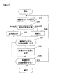
図10は、地図データ生成処理のフローチャートである。ステップS10において、形状判定部35が、未選択の道路区間を1つ選択する。ステップS20において、形状判定部35が、ステップS10で選択した道路区間を直線区間と曲線区間の一方に分類する。直線区間に分類した場合、形状判定部35は処理をステップS30に進める。ステップS30において、点列間引部36は、直線区間に分類された道路区間に対して点列間引処理を実行し、処理をステップS50に進める。ステップS20において道路区間が曲線区間に分類された場合、形状判定部35は処理をステップS40に進める。ステップS40において曲線化部37は、曲線区間に分類された道路区間に対して曲線化処理を実行し、処理をステップS50に進める。
FIG. 10 is a flowchart of map data generation processing. In step S10, the
ステップS50において、基準レーン変更部38は、ステップS10で選択された区間が一定の車線を有しているか、換言すると、例えば車線が分岐している道路区間ではないかを判定する。その道路区間において車線が変換していない場合、基準レーン変更部38は処理をステップS60に進める。ステップS60において基準レーン変更部38は、点列間引処理もしくは曲線化処理が施された道路形状データを基準レーン表現に変更する。
In step S50, the reference
ステップS70において、地図データ生成装置3は、未選択の道路区間が残っているか否かを判定する。未選択の道路区間が残っている場合、処理はステップS10に進む。他方、全ての道路区間が選択済みである場合、図10に示す地図データ生成処理は終了する。
In step S70, the map
上述した実施の形態によれば、次の作用効果が得られる。
(1)形状判定部35は、複数の地点104により道路形状を表現する第1形状データ21により道路形状が表現された道路を、直線区間と曲線区間とに分類する。点列間引部36は、直線区間の道路形状を第1表現による表現に変更する。曲線化部37は、曲線区間の道路形状を第1表現とは異なる第2表現による表現に変更する。データ出力部332は、点列間引部36および曲線化部37により変更された表現による道路形状のデータを第2形状データ41として出力する。このようにしたので、道路形状を最適に表現したデータ量の少ない地図データを生成することができる。
According to the embodiment described above, the following effects can be obtained.
(1) The
(2)レーン表現変更部38は、第1表現または第2表現で表現された複数の車線を含む道路の道路形状を、複数の車線のうち少なくとも1つの車線の道路形状と複数の車線の車線数および道路幅に関する情報とを含む表現に変更する。このようにしたので、地図データのデータ量をより削減することができる。
(2) The lane
(3)形状判定部35は、1つの直線区間および1つの曲線区間が、互いに異なる道路属性を有する複数の区間を含んでいる場合、複数の区間の各々を複数の直線区間および複数の曲線区間に分類する。このようにしたので、地図データのデータ量をより削減することができる。
(3) When one straight section and one curved section include a plurality of sections having road attributes different from each other, the
(4)第1表現は、複数の地点により直線区間の道路形状を表現した場合よりもデータ量が少ない表現であり、第2表現は、複数の地点により曲線区間の道路形状を表現した場合よりもデータ量が少ない表現である。このようにしたので、地図データのデータ量をより削減することができる。 (4) The first expression is an expression in which the amount of data is smaller than the case where the road shape of the straight section is expressed by a plurality of points, and the second expression is more than the case where the road shape of a curved section is expressed by a plurality of points Is also a representation with a small amount of data. Since this is done, the amount of map data can be further reduced.
(5)第1表現は、第1形状データ21に含まれる複数の地点よりも少ない数の地点によって直線区間の道路形状を表現する表現方式である。第2表現は、パラメトリック曲線により曲線区間の道路形状を表現する表現方式である。点列間引部36は、点列間引処理により直線区間の道路形状の表現を第1表現に変更する。曲線化部37は、曲線化処理により曲線区間の道路形状の表現を第2表現に変更する。このようにしたので、直線区間と曲線区間の各々を最適な表現方式で表現することができる。
(5) The first expression is an expression method for expressing the road shape of the straight section by the number of points smaller than the plurality of points included in the
(6)点列間引部36は、第1形状データ21における直線区間の道路形状と、第1表現により表現された直線区間の道路形状との差が所定量以内となるように点列間引処理を行う。曲線化部37は、第1形状データ21における曲線区間の道路形状と、第2表現により表現された曲線区間の道路形状との差が所定量以内となるように曲線化処理を行う。このようにしたので、所望の精度を有し、かつデータ量が少ない地図データを生成することができる。
(6) The point train thinning-out
次のような変形も本発明の範囲内であり、変形例の一つ、もしくは複数を上述の実施形態と組み合わせることも可能である。 The following modifications are also within the scope of the present invention, and one or more of the modifications can be combined with the above-described embodiment.
(変形例1)
図4(a)に図示した第1形状データ21とは異なる形状データを扱うようにしてもよい。例えば、図11に図示した第1形状データ21aのように、各々の地点104aが標高103を含んでいてもよい。この場合、点列間引部36および曲線化部37は、標高を考慮して道路区間を扱う。例えば点列間引部36は、一区間の形状データにおいて始点の標高と終点の標高とを直線で結び、この直線から最も標高が離れている地点とこの直線までの標高差を測定し、標高差が所定量を超えている場合、その地点は間引き後に残す地点とする。つまり点列間引部36は、平面的な距離だけでなく、鉛直方向の距離についても考慮して、基地図データ2における元の道路形状との差が所定値以内となるように、間引後の道路形状データにおいて地点を間引くか残すかを決定する。曲線化部37についても同様である。
(Modification 1)
Shape data different from the
上記では、種々の実施の形態および変形例を説明したが、本発明はこれらの内容に限定されるものではない。本発明の技術的思想の範囲内で考えられるその他の態様も本発明の範囲内に含まれる。 Although various embodiments and modifications have been described above, the present invention is not limited to these contents. Other embodiments considered within the scope of the technical idea of the present invention are also included within the scope of the present invention.
1…車両制御システム、2…基地図データ、3…地図データ生成装置、4…車両制御用地図データ、5…車両、6…車両制御装置、21…第1形状データ、35…形状判定部、36…点列間引部、37…曲線化部、38…レーン表現変更部、41…第2形状データ
DESCRIPTION OF
Claims (8)
前記直線区間の道路形状の表現を第1表現による表現に変更する点列間引部と、
前記曲線区間の道路形状の表現を前記第1表現とは異なる第2表現による表現に変更する曲線化部と、
前記点列間引部および前記曲線化部により変更された表現による道路形状のデータを第2形状データとして出力する出力部と、を備え、
前記第1表現または前記第2表現で表現された複数の車線を含む道路の道路形状を、前記複数の車線のうち少なくとも1つの車線の道路形状と前記複数の車線の車線数および道路幅に関する情報とを含む表現に変更するレーン表現変更部を更に備え、
前記レーン表現変更部は、前記複数の車線を含む道路の道路形状のうち少なくとも1つの車線について前記道路の道路形状のデータを削除し、
前記出力部は、前記レーン表現変更部により変更された表現による道路形状のデータを前記第2形状データとして出力する地図データ生成装置。 A shape determination unit that classifies a road whose road shape is represented by first shape data representing the road shape by a plurality of points into a straight section and a curved section;
A point sequence thinning unit which changes the representation of the road shape of the straight section to the representation by the first representation;
And a curved section to change the representation of the road shape of the curved section to representation by a different second representation from the first representation,
An output unit that outputs, as second shape data, road shape data according to the expression changed by the point row thinning unit and the curving unit ;
The road shape of a road including a plurality of lanes expressed in the first expression or the second expression, information on the road shape of at least one lane of the plurality of lanes, the number of lanes of the plurality of lanes, and the road width And a lane expression change unit for changing the expression to
The lane expression changing unit deletes data of the road shape of the road for at least one lane of the road shapes of the road including the plurality of lanes,
The said output part is a map data generation apparatus which outputs the data of the road shape by the expression changed by the said lane expression change part as said 2nd shape data .
前記形状判定部は、1つの前記直線区間または1つの前記曲線区間が、互いに異なる道路属性を有する複数の区間を含んでいる場合、前記複数の区間の各々を複数の前記直線区間または複数の前記曲線区間に分類する地図データ生成装置。 In the map data generation device according to claim 1 ,
The shape determination unit, when one of the straight sections or one of the curved sections includes a plurality of sections having different road attributes, each of the plurality of sections may be divided into a plurality of the straight sections or a plurality of the plurality of sections. Map data generation device that classifies into curved sections.
前記第1表現は、前記複数の地点により前記直線区間の道路形状を表現した場合よりもデータ量が少ない表現であり、
前記第2表現は、前記複数の地点により前記曲線区間の道路形状を表現した場合よりもデータ量が少ない表現である地図データ生成装置。 In the map data generation device according to claim 2 ,
The first expression is an expression having a smaller amount of data than the case where the road shape of the straight section is expressed by the plurality of points,
The map data generation device according to claim 2, wherein the second expression is an expression having a smaller amount of data than the case where the road shape of the curved section is expressed by the plurality of points.
前記第1表現は、前記複数の地点よりも少ない数の地点によって前記直線区間の道路形状を表現し、
前記第2表現は、パラメトリック曲線により前記曲線区間の道路形状を表現し、
前記点列間引部は、点列間引処理により前記直線区間の道路形状の表現を前記第1表現に変更し、
前記曲線化部は、曲線化処理により前記曲線区間の道路形状の表現を前記第2表現に変更する地図データ生成装置。 In the map data generation device according to claim 3 ,
The first representation expresses the road shape of the straight section by a number of points smaller than the plurality of points,
The second expression represents the road shape of the curved section by a parametric curve,
The point sequence thinning unit changes the representation of the road shape of the straight section to the first representation by a point sequence thinning process.
The map data generating device, wherein the curving unit changes a road shape representation of the curved section to the second representation by curvilinear processing.
前記点列間引部は、前記第1形状データにおける前記直線区間の道路形状と、前記第1表現により表現された前記直線区間の道路形状との差が所定量以内となるように前記点列間引処理を行い、
前記曲線化部は、前記第1形状データにおける前記曲線区間の道路形状と、前記第2表現により表現された前記曲線区間の道路形状との差が所定量以内となるように前記曲線化処理を行う地図データ生成装置。 In the map data generation device according to claim 4 ,
The point sequence thinning-out unit is configured such that a difference between a road shape of the straight section in the first shape data and a road shape of the straight section represented by the first expression is within a predetermined amount. Do thinning process,
The curving unit performs the curving processing such that a difference between a road shape of the curved section in the first shape data and a road shape of the curved section represented by the second expression is within a predetermined amount. Map data generation device to do.
前記第1形状データは、前記複数の地点の標高に関する情報を含み、
前記点列間引部は、前記第1形状データにおける前記直線区間の鉛直方向における道路形状と、前記第1表現により表現された前記直線区間の鉛直方向における道路形状との差が所定量以内となるように前記点列間引処理を行い、
前記曲線化部は、前記第1形状データにおける前記曲線区間の鉛直方向における道路形状と、前記第2表現により表現された前記曲線区間の鉛直方向における道路形状との差が所定量以内となるように前記曲線化処理を行う地図データ生成装置。 In the map data generation device according to claim 5 ,
The first shape data includes information on the elevations of the plurality of points,
The point row thinning-out unit has a difference between a road shape in the vertical direction of the straight line section in the first shape data and a road shape in the vertical direction of the straight line section represented by the first expression within a predetermined amount Perform the point sequence thinning process to be
The curving unit is configured such that a difference between a road shape in the vertical direction of the curved section in the first shape data and a road shape in the vertical direction of the curved section represented by the second expression is within a predetermined amount. Map data generating device that performs the curve conversion process on
前記直線区間の道路形状の表現を第1表現による表現に変更する点列間引工程と、
前記曲線区間の道路形状の表現を前記第1表現とは異なる第2表現による表現に変更する曲線化工程と、
前記点列間引工程および前記曲線化工程により変更された表現による道路形状のデータを第2形状データとして出力する出力工程と、
前記第1表現または前記第2表現で表現された複数の車線を含む道路の道路形状を、前記複数の車線のうち少なくとも1つの車線の道路形状と前記複数の車線の車線数および道路幅に関する情報とを含む表現に変更するレーン表現変更工程とを含み、
前記レーン表現変更工程では、前記複数の車線を含む道路の道路形状のうち少なくとも1つの車線について前記道路の道路形状のデータを削除し、
前記出力工程では、前記レーン表現変更工程により変更された表現による道路形状のデータを前記第2形状データとして出力する地図データ生成方法。 A shape determination step of classifying a road whose road shape is represented by first shape data representing the road shape by a plurality of points into a straight section and a curved section;
A point train thinning step of changing the representation of the road shape of the straight section into the representation by the first representation;
A curving step of changing the representation of the road shape of the curved section into a second representation different from the first representation;
An output step of outputting, as second shape data, road shape data according to the expression changed by the point row thinning step and the curving step;
The road shape of a road including a plurality of lanes expressed in the first expression or the second expression, information on the road shape of at least one lane of the plurality of lanes, the number of lanes of the plurality of lanes, and the road width And changing the lane expression to the expression including
In the lane expression change step, data of the road shape of the road is deleted for at least one lane of the road shapes of the road including the plurality of lanes,
Wherein in the output step, maps data generation method for outputting data of a road shape by altered expression by the lane representing changing step as said second shape data.
前記直線区間の道路形状の表現を第1表現による表現に変更する点列間引ステップと、
前記曲線区間の道路形状の表現を前記第1表現とは異なる第2表現による表現に変更する曲線化ステップと、
前記点列間引ステップおよび前記曲線化ステップにより変更された表現による道路形状のデータを第2形状データとして出力する出力ステップと、
前記第1表現または前記第2表現で表現された複数の車線を含む道路の道路形状を、前記複数の車線のうち少なくとも1つの車線の道路形状と前記複数の車線の車線数および道路幅に関する情報とを含む表現に変更するレーン表現変更ステップとをコンピュータに実行させ、
前記レーン表現変更ステップでは、前記複数の車線を含む道路の道路形状のうち少なくとも1つの車線について前記道路の道路形状のデータを削除し、
前記出力ステップでは、前記レーン表現変更ステップにより変更された表現による道路形状のデータを前記第2形状データとして出力させる地図データ生成プログラム。 A shape determination step of classifying a road whose road shape is represented by first shape data representing the road shape by a plurality of points into a straight section and a curved section;
A point train thinning step of changing the representation of the road shape of the straight section into the representation by the first representation;
Changing the representation of the road shape of the curved section into a second representation different from the first representation;
Outputting the data of the road shape according to the expression changed by the point sequence thinning step and the curving step as second shape data;
The road shape of a road including a plurality of lanes expressed in the first expression or the second expression, information on the road shape of at least one lane of the plurality of lanes, the number of lanes of the plurality of lanes, and the road width And causing the computer to execute a lane expression change step of changing the expression to
In the lane expression change step, data of the road shape of the road is deleted for at least one lane of the road shapes of the road including the plurality of lanes,
Wherein in the output step, maps data generation program to output the data of the road shape by altered expression by the lane representing changing step as said second shape data.
Priority Applications (1)
| Application Number | Priority Date | Filing Date | Title |
|---|---|---|---|
| JP2016029894A JP6530331B2 (en) | 2016-02-19 | 2016-02-19 | Map data generation apparatus, map data generation method and map data generation program |
Applications Claiming Priority (1)
| Application Number | Priority Date | Filing Date | Title |
|---|---|---|---|
| JP2016029894A JP6530331B2 (en) | 2016-02-19 | 2016-02-19 | Map data generation apparatus, map data generation method and map data generation program |
Publications (2)
| Publication Number | Publication Date |
|---|---|
| JP2017146530A JP2017146530A (en) | 2017-08-24 |
| JP6530331B2 true JP6530331B2 (en) | 2019-06-12 |
Family
ID=59683106
Family Applications (1)
| Application Number | Title | Priority Date | Filing Date |
|---|---|---|---|
| JP2016029894A Active JP6530331B2 (en) | 2016-02-19 | 2016-02-19 | Map data generation apparatus, map data generation method and map data generation program |
Country Status (1)
| Country | Link |
|---|---|
| JP (1) | JP6530331B2 (en) |
Families Citing this family (3)
| Publication number | Priority date | Publication date | Assignee | Title |
|---|---|---|---|---|
| EP3385673B1 (en) * | 2017-04-07 | 2023-07-05 | Continental Automotive Technologies GmbH | Method and device for the reducing the number of intermediate nodes in a route |
| JP7077999B2 (en) * | 2019-03-20 | 2022-05-31 | 株式会社デンソー | Map data output device |
| KR102913811B1 (en) * | 2023-03-21 | 2026-01-19 | 주식회사 모라이 | Method and system for generating road shape information by ensuring road continuity in virtual environment |
Family Cites Families (3)
| Publication number | Priority date | Publication date | Assignee | Title |
|---|---|---|---|---|
| JP3273574B2 (en) * | 1992-07-31 | 2002-04-08 | 東京瓦斯株式会社 | Map data compression device |
| JP2007072011A (en) * | 2005-09-05 | 2007-03-22 | Zenrin Co Ltd | Device for creating road network data, method for creating road network data, and data structure of road network data |
| JP4382776B2 (en) * | 2006-07-14 | 2009-12-16 | アイシン・エィ・ダブリュ株式会社 | Vehicle control device |
-
2016
- 2016-02-19 JP JP2016029894A patent/JP6530331B2/en active Active
Also Published As
| Publication number | Publication date |
|---|---|
| JP2017146530A (en) | 2017-08-24 |
Similar Documents
| Publication | Publication Date | Title |
|---|---|---|
| CN109459050B (en) | Recommended method and device for navigation route | |
| CN102934150B (en) | Driving model creating apparatus and driving support apparatus | |
| JP6026295B2 (en) | Curve shape modeling apparatus, method, and in-vehicle navigation apparatus | |
| JP6161942B2 (en) | Curve shape modeling device, vehicle information processing system, curve shape modeling method, and curve shape modeling program | |
| CN111859178B (en) | Method and system for recommending boarding point | |
| CN110140026B (en) | Vehicle-mounted device, map update system | |
| CN110749329A (en) | A lane-level topology construction method and device based on structured road | |
| WO2019114805A1 (en) | Method for determining safe speed information of road | |
| CN110196592A (en) | A kind of update method of trajectory line, system, terminal and storage medium | |
| JPWO2019065409A1 (en) | Map generation method for autonomous driving simulator and autonomous driving simulator | |
| CN113191550A (en) | Map matching method and device | |
| CN104412309B (en) | Recommended-drive-pattern generation device and method | |
| JP6530331B2 (en) | Map data generation apparatus, map data generation method and map data generation program | |
| US11781875B2 (en) | Apparatus and method for forming and analyzing connected roads | |
| JP6128960B2 (en) | Road gradient data creation device, vehicle energy consumption calculation device, and road gradient data creation method | |
| CN102564442B (en) | Method and device for displaying road segments and method of providing a map data base | |
| WO2007111062A1 (en) | Information creation device and information creation method | |
| EP2772895A1 (en) | Method and Apparatus for Transit Mapping | |
| JP5864327B2 (en) | GUIDING LINE GENERATION DEVICE, GUIDING LINE GENERATION METHOD, AND COMPUTER PROGRAM | |
| US20220404155A1 (en) | Alternative Navigation Directions Pre-Generated When a User is Likely to Make a Mistake in Navigation | |
| KR20170070488A (en) | Method and apparatus for automatically generating drive route | |
| JP2013185893A (en) | Route guidance system | |
| JP2008076593A (en) | Simplified map generating apparatus and simplified map generation method | |
| JP2018173512A (en) | Traffic lane information generation device, traffic lane information generation method, and program for traffic lane information generation | |
| KR20230009234A (en) | Apparatus, method and server for navigating the movement route of a vehicle at the lane level |
Legal Events
| Date | Code | Title | Description |
|---|---|---|---|
| RD04 | Notification of resignation of power of attorney |
Free format text: JAPANESE INTERMEDIATE CODE: A7424 Effective date: 20170921 |
|
| A621 | Written request for application examination |
Free format text: JAPANESE INTERMEDIATE CODE: A621 Effective date: 20180510 |
|
| A977 | Report on retrieval |
Free format text: JAPANESE INTERMEDIATE CODE: A971007 Effective date: 20190215 |
|
| A131 | Notification of reasons for refusal |
Free format text: JAPANESE INTERMEDIATE CODE: A131 Effective date: 20190226 |
|
| A521 | Written amendment |
Free format text: JAPANESE INTERMEDIATE CODE: A523 Effective date: 20190410 |
|
| TRDD | Decision of grant or rejection written | ||
| A01 | Written decision to grant a patent or to grant a registration (utility model) |
Free format text: JAPANESE INTERMEDIATE CODE: A01 Effective date: 20190514 |
|
| A61 | First payment of annual fees (during grant procedure) |
Free format text: JAPANESE INTERMEDIATE CODE: A61 Effective date: 20190516 |
|
| R150 | Certificate of patent or registration of utility model |
Ref document number: 6530331 Country of ref document: JP Free format text: JAPANESE INTERMEDIATE CODE: R150 |