JP6536268B2 - Anticorrosion method - Google Patents
Anticorrosion method Download PDFInfo
- Publication number
- JP6536268B2 JP6536268B2 JP2015155637A JP2015155637A JP6536268B2 JP 6536268 B2 JP6536268 B2 JP 6536268B2 JP 2015155637 A JP2015155637 A JP 2015155637A JP 2015155637 A JP2015155637 A JP 2015155637A JP 6536268 B2 JP6536268 B2 JP 6536268B2
- Authority
- JP
- Japan
- Prior art keywords
- soil
- steel material
- particles
- steel
- particle size
- Prior art date
- Legal status (The legal status is an assumption and is not a legal conclusion. Google has not performed a legal analysis and makes no representation as to the accuracy of the status listed.)
- Expired - Fee Related
Links
Images





Landscapes
- Preventing Corrosion Or Incrustation Of Metals (AREA)
Description
本発明は、防食工法に関し、より詳しくは、土壌改質による鋼製材料の防食工法に関する。 The present invention relates to an anticorrosion method, and more particularly to an anticorrosion method of steel material by soil modification.
屋外で使用される鋼製材料は、厳しい腐食環境に曝されることがある。例えば、鋼矢板は、連続的に並べて地中に打ち込まれ、矢板壁を形成して、河川、海岸、港湾などの護岸に用いられる。また例えば、鋼管杭は、地中や海底などに打ち込まれて、構造物などの基礎に用いられる。その結果、鋼矢板や鋼管杭などの鋼製材料は、地中や海中の土砂、泥、瓦礫などに直接激しく接するので、著しい腐食が起こりやすい。特に、地中は非常に過酷な腐食環境であるため、効果的な防食対策が望まれている。さらに、鋼製材料を酸性硫酸塩土壌環境に用いる場合には、土中に含まれるパイライトの酸性反応によりpHが著しく低下するため極めて腐食性が高く、より効果的な防食対策が望まれる。 Steel materials used outdoors may be exposed to severe corrosive environments. For example, steel sheet piles are continuously lined up and driven into the ground to form a sheet pile wall and used for revetment of rivers, beaches, ports and the like. Further, for example, a steel pipe pile is driven into the ground or the sea floor and used as a foundation of a structure or the like. As a result, since steel materials such as steel sheet piles and steel pipe piles are in direct contact with soil, mud, rubble, etc. in the ground or in the sea, significant corrosion is likely to occur. In particular, since the ground is a very severe corrosive environment, effective anticorrosion measures are desired. Furthermore, in the case of using a steel material in an acid sulfate soil environment, the pH is extremely lowered due to the acid reaction of pyrite contained in the soil, so the corrosion resistance is extremely high, and more effective anticorrosion measures are desired.
従来から用いられる防食対策は、鋼製材料の表面に樹脂からなる防食被膜を形成する方法、防食電流を付与する電気防食方法、コンクリート、モルタル及びレンジモルタルなどで鋼材表面を被覆する防食工法、鋼製材料の接する土壌を改質する方法などがある。防食被膜を形成する方法は、鋼製材料を土壌に打ち込む際に被膜の一部が剥がれ、充分な防食効果が得られなくなることがある。電気防食方法は、土壌の電気抵抗が非常に大きいため、大きな防食電流を流す必要がある。また、電気防食方法は、周囲の通信設備に障害を生じたり、周囲の他の鋼材に迷走電流による腐食を生じたりすることがある。鋼材表面を被覆する防食工法は、コンクリートなどにひび割れが生じた場合、ひび割れからコンクリートなどの内部に酸素及び水素イオンが容易に侵入することができる。その結果、鋼材が著しく腐食する可能性がある。また、この被覆する防食工法は、例えば、特開平5−171658号公報(特許文献1)や特開平7−054336号公報(特許文献2)の防食工法がある。特開平7−054336号公報には、地下空間を囲う壁体用鋼材と壁体用鋼材の外側を囲う鋼製隔壁体との間に鉄筋コンクリートを打設して、壁体用鋼材の外側の表面をコンクリートで被覆する防食工法が開示されている。この工法では、壁体用鋼材と鋼製隔壁体とが必要になるため、鋼の使用量が非常に多くなり、施工費用が著しく増大する。 Conventionally used anticorrosion measures include a method of forming an anticorrosion coating made of resin on the surface of a steel material, an anticorrosion method of imparting an anticorrosion current, an anticorrosion method of covering a steel surface with concrete, mortar and range mortar, steel There is a method of reforming the soil in contact with the material. In the method of forming the anticorrosive film, when the steel material is driven into the soil, a part of the film may be peeled off, and a sufficient anticorrosive effect may not be obtained. In the case of the cathodic protection method, since the electrical resistance of the soil is very large, it is necessary to apply a large corrosion current. In addition, the method of cathodic protection may cause damage to surrounding communication equipment or may cause corrosion of other steel materials in the surrounding area due to stray current. In the anticorrosion method for coating the surface of steel materials, when cracks occur in concrete or the like, oxygen and hydrogen ions can easily penetrate into the inside of concrete or the like from the cracks. As a result, the steel may be significantly corroded. Further, as the anticorrosion method to be covered, there are, for example, the anticorrosion method of JP-A-5-171658 (Patent Document 1) and JP-A-7-054336 (Patent Document 2). In Japanese Patent Laid-Open No. 7-054336, reinforced concrete is cast between a steel for a wall surrounding the underground space and a steel partition surrounding the outer side of the steel for a wall to form an outer surface of the steel for a wall. Discloses an anticorrosion method for covering the surface with concrete. In this construction method, since the steel for the wall and the partition wall made of steel are required, the amount of steel used is extremely large and the construction cost is remarkably increased.
土壌を改質する方法は、例えば、特開2001−11668号公報(特許文献3)の防食工法がある。同公報には、施工の際、鋼製材料に接する土壌に、アルカリ性の土壌改質剤を混合して、鋼製材料から少なくとも10mmまでの範囲にある土壌のpHを6〜13にする土壌改質を行う防食工法が開示されている。 As a method of reforming the soil, for example, there is an anticorrosion method disclosed in Japanese Patent Application Laid-Open No. 2001-11668 (Patent Document 3). In the same publication, a soil improvement agent is mixed with a soil in contact with a steel material at the time of construction so that the pH of the soil in the range from at least 10 mm from the steel material is 6 to 13 An anticorrosion method of quality is disclosed.
前記防食工法は、土壌改質剤を添加して酸性土壌のpHを中性〜アルカリ性に変えることで、鋼製材料を防食している。しかしながら、この技術は、土壌の土粒子に関する観点からは開発がなされていない。そのため、土粒子同士の隙間が大きい場合には、たとえ土壌のpHを中性〜アルカリ性に改質されたとしても、地表面からの酸素が十分に供給されていると、パイライトの酸化反応により土壌のpHが低下して、鋼製材料に著しい腐食損傷を生じる恐れがある。 The above-mentioned anticorrosion method protects the steel material by adding a soil modifying agent to change the pH of acidic soil to neutral to alkaline. However, this technology has not been developed in terms of soil particles in the soil. Therefore, when the space between soil particles is large, even if the pH of the soil is modified to neutral to alkaline, if the oxygen from the ground surface is sufficiently supplied, the oxidation reaction of pyrite causes the soil to react. The pH of the steel may decrease to cause significant corrosion damage to the steel material.
本発明の目的は、土壌改質により鋼製材料を防食可能な防食工法を提供することである。 An object of the present invention is to provide an anticorrosion method capable of preventing corrosion of steel materials by soil modification.
本発明の一実施形態による防食工法は、鋼製材料の防食工法である。土壌に穴を掘る工程と、JIS1204:2009の粒径区分で粗砂又はそれよりも小さい土粒子を穴に詰める工程と、鋼製材料を土粒子に打ち込む工程とを含む。 The anticorrosion method according to an embodiment of the present invention is an anticorrosion method of a steel material. The process includes the steps of drilling a hole in the soil, packing coarse sand or smaller soil particles into holes in the particle size classification of JIS 1204: 2009, and driving a steel material into the soil particles.
本発明によれば、土壌改質により鋼製材料を防食することができる。 According to the present invention, the steel material can be protected from corrosion by soil modification.
本発明者らは、土壌に接触する鋼製材料を土壌改質により防食するため、種々の検討を行い、以下の(A)〜(D)の知見を得た。 The present inventors conducted various studies to prevent corrosion of steel materials in contact with soil by soil modification, and obtained the following findings (A) to (D).
(A)土壌腐食環境において、酸性硫酸塩土壌(以下、酸性土という)は、時間経過でpHが低下しやすく、腐食環境が非常に厳しい。pHの低下は、土壌中に含まれるパイライト(FeS2)の酸化反応により硫酸を生成するためである。パイライトと水と土粒子とが存在する環境(以下、土壌系という)は、パイライトと水とからなるパイライト分散溶液の環境(以下、溶液系という)に比べて腐食速度が小さくなることが分かった。土壌系では、例えば、図1に示すように、土粒子3が酸素や水素イオンの拡散の障害となり、土粒子3間に生じる隙間が酸素や水素イオンの拡散経路9になることで、パイライト8への酸素の供給や鋼製材料1への酸素及び水素イオンの供給が遅くなり、腐食速度が小さくなると考えられる。
(A) Soil corrosion environment In an acid sulfate soil (hereinafter referred to as acid soil), the pH tends to decrease with time, and the corrosion environment is very severe. The decrease in pH is to generate sulfuric acid by the oxidation reaction of pyrite (FeS 2 ) contained in the soil. It was found that the environment in which pyrite, water and soil particles exist (hereinafter referred to as soil system) has a lower corrosion rate than the environment (hereinafter referred to as solution system) of a pyrite dispersed solution consisting of pyrite and water . In the soil system, for example, as shown in FIG. 1, the
(B)土壌系では、土粒子3の平均粒径が小さくなると、鋼製材料1の腐食速度が小さくなり、平均粒径が大きくなると、溶液系の腐食速度に近づく傾向があることが分かった。これは、土粒子3が細かいほど、拡散経路9が減少したり狭まったりするなどで拡散が制限され、土粒子3が粗いほど、拡散経路9が増加したり広がったりするなどで拡散が容易になるためと考えられる。ここで、土壌系及び溶液系において、酸素及び水素イオンの拡散速度を測定した結果、土壌系は溶液系に比べて酸素及び水素イオンの拡散速度が遅くなることが確認された。
(B) It was found that in the soil system, the corrosion rate of the
(C)溶液系では腐食が進行しても低pHを維持するのに対し、土壌系では日数経過に伴い土壌と鋼製材料との界面のpHが上昇し、界面を低pHに維持できなくなることが分かった。さらに、土壌系では、界面のpHが上昇しても、土壌の鋼製材料から30mm離れた位置(以下、バルク部という)のpHが低pHを維持することが分かった。これは、鋼製材料の腐食により水素イオンが消費されることでpHが上昇に向かうところ、溶液系では、パイライトの酸化反応により水素イオンが継続的に供給されることで、低pHに維持されるものであると考えられる。そして、土壌系では、酸素や水素イオンの拡散が制限される(遅れる)ことで、鋼製材料の周囲において水素イオンの消費に水素イオンの供給が追いつかず、界面のpHが上昇するものであると考えられる。 (C) In the solution system, although the low pH is maintained even when the corrosion progresses, in the soil system, the pH at the interface between the soil and the steel material increases with the passage of days, and the interface can not be maintained at the low pH I found that. Furthermore, in the soil system, it was found that the pH at a position 30 mm away from the steel material of the soil (hereinafter referred to as the bulk part) maintains a low pH even when the pH of the interface rises. This is because pH is increased by consumption of hydrogen ions by corrosion of steel materials, and in solution systems, hydrogen ions are continuously supplied by oxidation reaction of pyrite to maintain low pH. It is considered to be And, in the soil system, the diffusion of oxygen and hydrogen ions is restricted (delayed), the supply of hydrogen ions can not catch up with the consumption of hydrogen ions around the steel material, and the pH of the interface rises. it is conceivable that.
(D)また、土壌2は、例えば、図2に示すように、通常、酸性土の層6と中性土の層7などの複数の異質の土の層が積み重なるものである。そのため、鋼製材料は、十数mの深さまで土壌2に打ち込むと、複数の層に接触して、層間でのマクロセル腐食を生じることが分かった。
(D) Also, as shown in FIG. 2, the
本発明者らは、前述の知見に基づいて本発明を完成させた。まず、本発明の一実施形態の概要を説明する。 The present inventors completed the present invention based on the above-mentioned findings. First, an outline of an embodiment of the present invention will be described.
防食工法は、鋼製材料の防食工法である。土壌に穴を掘る工程と、JIS1204:2009の粒径区分で粗砂又はそれよりも小さい土粒子を穴に詰める工程と、鋼製材料を土粒子に打ち込む工程とを含む。 The anticorrosion method is an anticorrosion method of steel material. The process includes the steps of drilling a hole in the soil, packing coarse sand or smaller soil particles into holes in the particle size classification of JIS 1204: 2009, and driving a steel material into the soil particles.
この防食工法は、土壌における鋼製材料の設置場所及び周囲の領域を、粒径区分で粗砂又はそれよりも小さい土粒子に交換することで、土壌を改質する。その結果、土壌中の鋼製材料の周囲で酸素及び水素イオンの拡散が制限され、例えばパイライトを含む酸性土であっても鋼製材料の周囲のpHが上昇する。 This anticorrosion method reforms the soil by replacing the installation location and surrounding area of the steel material in the soil with coarse sand or smaller soil particles in the particle size division. As a result, the diffusion of oxygen and hydrogen ions is limited around the steel material in the soil, and the pH around the steel material is increased even in the case of, for example, acidic soil containing pyrite.
好ましくは、土粒子が、粒径区分で、粗砂、中砂、細砂、シルト、及び粘土からなる群から選ばれる1種である。 Preferably, the soil particles are one selected from the group consisting of coarse sand, medium sand, fine sand, silt, and clay in the particle size division.
この防食工法は、1種のみの土粒子を穴に詰めることで、例えば2種以上の土粒子を混合して詰める場合に生じる混合むら(不均一性)などを回避することができる。その結果、不均一性などに伴うマクロセル腐食の発生を抑制することができ、鋼製材料の腐食を抑制することができる。 In this anticorrosion method, it is possible to avoid mixing unevenness (unevenness) and the like that occur when, for example, two or more types of soil particles are mixed and packed by packing only one type of soil particles in the hole. As a result, it is possible to suppress the occurrence of macro cell corrosion due to nonuniformity and the like, and to suppress the corrosion of the steel material.
好ましくは、打ち込まれた鋼製材料から穴の内面までの距離が30mm以上である。 Preferably, the distance from the driven steel material to the inner surface of the hole is at least 30 mm.
この防食工法は、土粒子を交換していない領域(既存の土の層)から鋼製材料を十分離すことができ、鋼製材料への水素イオンと酸素の供給がさらに遅くなり、腐食速度をさらに遅くすることができる。 This anticorrosion method can sufficiently separate the steel material from the area (the existing soil layer) where soil particles are not exchanged, and the supply of hydrogen ions and oxygen to the steel material is further delayed, and the corrosion rate is increased. It can be even slower.
[防食工法]
以下、本発明の一実施形態による鋼製材料1の防食工法について詳細に説明する。
防食工法を用いる土壌2は、例えば、図2に示すように、酸性土の層6と中性土の層7とが積み重なるものであるが、酸性土の層6のみや3以上の層が積み重なるものであってもよく、特にこれらに限定されない。防食工法に用いる鋼製材料1は、例えば、H形鋼、鋼管杭、あるいは鋼矢板などであるが、特にこれらに限定されない。鋼製材料1は、土壌2に打ち込まれることで、土壌2に設置される。
[Anti-corrosion method]
Hereinafter, the anticorrosion method of the
The
防食工法は、土壌改質により鋼製材料1を防食する施工方法である。防食工法は、図3に示すように、土壌2に穴4を掘る工程S1と、土粒子3を穴4に詰める工程S2と、鋼製材料1を土粒子3に打ち込む工程S3とを含む。
The anticorrosion method is a construction method in which the
工程S1は、例えば、図4に示すように、ボーリング機材により土壌2の所定の領域を掘削して、大気中に開放された穴4を土壌2に形成する。土壌2を掘削する(穴4を掘る)方法は、ボーリング機材による掘削に限らず、周知の方法が適用され、特に限定されない。
In step S1, for example, as shown in FIG. 4, a predetermined region of the
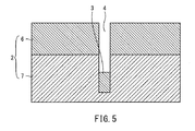
工程S2は、工程S1後に行われる。工程S2は、例えば、図5に示すように、穴4に所定量の土粒子3を入れた後、例えば、図6に示すように、穴4に重錘5を落とす重錘落下締め固め工法などで、穴4に入れた土粒子3を締め固める。工程S2は、図7に示すように、締め固めた土粒子3の表面が土壌2の表面と並ぶまで、穴4に土粒子3を入れて締め固めることを所定回数(1回以上)行う。その結果、穴4には、土壌2の穴4の周辺と同程度あるいは鋼製材料1を支持可能な程度の固さで、新たな土粒子3が詰められる。工程S2の土粒子3を詰める方法は、例示のものに限らず、周知の方法を適用でき、特に限定されない。
Step S2 is performed after step S1. In step S2, for example, as shown in FIG. 5, after putting a predetermined amount of
穴4に詰める土粒子3は、JIS 1204:2009の粒径区分で粗砂又はそれよりも小さい土粒子3である。つまり、工程S2は、土壌2の所定の領域(穴4)の土粒子3を、粒径が調整された土粒子3に交換する。粗砂又はそれよりも小さい土粒子3とは、JIS 1204:2009において、粒径2mm以下の土粒子である。粒径2mm以下とは、JIS 1204:2009の土粒度試験方法に基づき、土粒子3を格子状のふるいにかけ、2mm×2mmの格子を通過した土粒子3の重量比率が50%以上を表す(有効粒径D50)。そして、粒径区分は、JIS 1204:2009に基づき、0.850〜2mmが粗砂、0.250〜0.850mmが中砂、0.075〜0.250mmが細砂、0.075mm以下の細粒分であるシルト及び粘土である。シルトは0.075〜0.005mmであり、粘土は0.005mm以下である。穴4に詰める土粒子3は、知見のとおり粒径が小さいほど好ましく、より好ましくは細砂以下である。
The
工程S3は、例えば工程S2後に行われる。工程S3は、例えば、図8に示すように、鋼製材料1が鋼管杭である場合、鋼管杭を穴4に充填した土粒子3に打ち込み、鋼管杭を土壌2に設置する。鋼製材料1は、土壌2に埋まる部位全面が工程S2で入れた土粒子3に接触する。その結果、鋼製材料1は、粒径が調整された土粒子3に囲まれて土壌2に設置される。鋼製材料1が土粒子3に囲まれる領域11は、鋼製材料1を設置した後に土粒子3が存在する領域(置換土壌外周領域ともいう)である。具体的には、領域11は、打ち込まれた鋼製材料1から穴4の内面までの領域であり、穴4の内面は穴4の周壁及び底面を含む。さらに、鋼製材料1から穴4の内面(周壁及び底面)までの距離はいずれも、30mm以上であることが好ましい。つまり、工程S1において、この距離を確保可能な寸法で穴4を掘ることが好ましい。鋼製材料1を打ち込む方法は、周知の方法を適用でき、特に限定されない。
Step S3 is performed, for example, after step S2. Step S3 is, for example, as shown in FIG. 8, when the
以上の通り、防食工法は、土壌2における鋼製材料1の設置場所及び周囲の領域を、粒径区分で粗砂又はそれよりも小さい土粒子3に交換する。その結果、土壌2における鋼製材料1の周囲で酸素及び水素イオンの拡散が制限され、パイライトを含む酸性土であっても、鋼製材料1の周囲の領域11(置換土壌外周領域)における土粒子3でのpHが上昇して、土壌2に設置した鋼製材料1を防食することができる。そして、防食工法は、同一条件に整えた1つの土の層(粒径を調整した土粒子3)で鋼製材料1の土壌2に位置する部位全面を覆うことができる。その結果、例えば複数の異質の層を有する土壌2であっても層間のマクロセル腐食の発生を抑制することができ、鋼製材料1を防食することができる。さらに、防食工法は、土粒子3を交換していない領域(既存の土の層)から領域11により鋼製材料1を十分離すことができる。その結果、防食工法は、鋼製材料1への水素イオンと酸素の供給がさらに遅くなり、腐食速度をさらに遅くすることができる。
As described above, in the anticorrosion method, the installation location and surrounding area of the
さらに、防食工法は、工程S2において、単一の粒径区分の土粒子3(1種の土粒子3)を入れることが好ましい。その結果、土壌2の鋼製材料1の周囲において、例えば土粒子3の不均一性などに伴うマクロセル腐食の発生をさらに抑制することができ、鋼製材料の腐食をさらに抑制することができる。なお、単一の区分範囲の土粒子3とは、例えば、粗砂、中砂、細砂、シルト、及び粘土からなる群から選ばれる1種を指すが、特にこれに限定されない。
Furthermore, in the corrosion prevention method, it is preferable to put soil particles 3 (one kind of soil particles 3) of a single particle size division in step S2. As a result, in the periphery of the
次に、実施例について説明する。実施例での条件は、本発明の実施可能性及び効果を確認するために採用した一条件例であり、本発明は、この一条件例に限定されるものではない。本発明は、本発明の要旨を逸脱せず、本発明の目的を達成する限りにおいて、種々の条件を採用し得るものである。 Next, an example will be described. The conditions in the examples are one condition example adopted to confirm the practicability and effects of the present invention, and the present invention is not limited to the one condition example. The present invention can adopt various conditions as long as the object of the present invention is achieved without departing from the scope of the present invention.
表1は、No.1〜4の試験片における、土粒子3の条件および実験結果である。No.1〜3はパイライト8を含む土壌系での浸漬試験を行い、No.4はパイライト8を含む溶液系での浸漬試験を行った。溶液系は、図9に示すように、水及びパイライト8からなる175mLのパイライト分散溶液10(4.9g/L FeS2)に、試験片11の全面を接触させてパイライト分散溶液10の中央付近に浸漬した。土壌系は、溶液系と同じ条件で67mLのパイライト分散溶液10に、溶液系と同量の体積となるよう土粒子3を加えたものに、試験片11の全面を接触させて土壌2の中央付近に浸漬した(埋め込んだ)。No.1の土粒子3は粒径2mm以下で構成され平均粒径0.2mmの細砂であり、No.2の土粒子3は粒径2mm以下で構成され平均粒径0.85mmの粗砂であり、No.3の土粒子3は平均粒径3mmの礫である。平均粒径には、JIS 1204:2009の土粒度試験方法に基づき、粒径加積曲線の通過質量百分率が50%に該当する粒径(有効粒径D50)を用いた。試験片11は、JIS SS400の鋼材から得たもの(25mm×50mm×6mm)を供試材とした。試験条件は、初期pHが4.0、試験温度が40℃、雰囲気が大気開放とした。
Table 1 shows No. It is the conditions of the

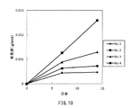
No.1〜4は、図10に示すように、7日後及び14日後、回収した試験片11から腐食生成物を除去した重量減(g/cm2)を測定した。図11に示すように、No.1〜3は、7日後及び14日後、試験片11と土壌2との界面(位置P1)のpH及びバルク部(位置P2)のpHを測定し、No.4は、7日後及び14日後、パイライト分散溶液10(位置P1)のpHを測定した。図11において、No.1A,2A,3AがNo.1,2,3の界面の測定結果であり、No.1B,2B,3BがNo.1,2,3のバルク部の測定結果である。なお、位置P2は、土壌2内において試験片11との界面(位置P1)から側方に30mm離れた位置である。また、No.4は位置P1と位置P2とでpHに差を生じないため、位置P2での測定を行っていない。
No. As shown in FIG. 10, the weight loss (g / cm < 2 >) which removed the corrosion product from the
7日後の重量減は、No.1〜3が0.001g/cm2未満であったのに対し、No.4が0.001g/cm2以上であった。そして、14日後の重量減は、No.1及び2が0.001g/cm2未満であったのに対し、No.3及び4が0.001g/cm2以上であった。 The weight loss after 7 days is no. No. 1 to 3 were less than 0.001 g / cm 2 . 4 was 0.001 g / cm 2 or more. And the weight loss after 14 days is No. No. 1 and 2 were less than 0.001 g / cm 2 . 3 and 4 were 0.001 g / cm 2 or more.
7日後の各pHは、No.1〜3の各位置P1が5以上であったのに対し、No.4が5未満であった。そして、位置P2での各pHはいずれも5未満であった。また、14日後の各pHは、No.1及び2の各位置P1が6以上であったのに対し、No.3の位置P1及びNo.4が6未満であった。そして、位置P2での各pHは、No.1が5未満であり、No.2及び3が6未満であった。 Each pH after 7 days was no. Although each position P1 of 1-3 was five or more, No. 4 was less than 5. And each pH in position P2 was less than five. Moreover, each pH after 14 days is No. While each position P1 of 1 and 2 was 6 or more, No. Position P1 and No. 3 4 was less than 6. And each pH in position P2 is No. No. 1 is less than 5 and no. 2 and 3 were less than 6.
このように、No.1及び2は、位置P1において、14日後の各pHが初期pHから中性程度に上昇した。さらに、No.1及び2は、7日後以降の腐食速度が小さくなった。また、No.1は、位置P2において14日後も低pHを維持した。 Thus, no. As for 1 and 2, at position P1, each pH after 14 days increased from the initial pH to about neutral. Furthermore, no. The corrosion rates after 1 day and 2 decreased after 7 days. Also, no. 1 maintained a low pH even after 14 days at position P2.
本発明によれば、鋼矢板や鋼管杭の施工に利用できる。 According to the present invention, it can be used for construction of steel sheet piles and steel pipe piles.
1:鋼製材料
2:土壌
3:土粒子
4:穴
5:重錘
6:酸性土の層
7:中性土の層
8:パイライト
9:拡散経路
10:パイライト分散溶液
11:領域
P1:位置(界面)
P2:位置(バルク部)
S1:工程
S2:工程
S3:工程
1: Steel material 2: Soil 3: Soil particle 4: Hole 5: Weight 6: 6: Layer of acidic soil 7: Layer of neutral soil 8: Pyrite 9: Diffusion path 10: Dispersion solution of pyrite 11: Area P1: Position (interface)
P2: Position (bulk part)
S1: Process S2: Process S3: Process
Claims (2)
土壌に穴を掘る工程と、
JIS1204:2009の粒径区分で粗砂又はそれよりも小さい土粒子を前記穴に詰める工程と、
前記鋼製材料を前記土粒子に打ち込む工程とを含み、
前記土粒子は、前記粒径区分で、粗砂、中砂、細砂、シルト、及び粘土からなる群から選ばれる単一の粒径区分の土粒子であり、
前記鋼製材料は、土壌に位置する部位全面が前記単一の粒径区分の土粒子によって覆われている、防食工法。 Anti-corrosion method of steel material,
Drilling a hole in the soil,
Packing coarse sand or smaller earth particles into the holes in the particle size classification of JIS 1204: 2009;
Look including a step of implanting the steel material to the soil particles,
The soil particles are soil particles of a single particle size classification selected from the group consisting of coarse sand, medium sand, fine sand, silt, and clay in the particle size classification ,
The said steel-made material is an anticorrosion method in which the whole site | part located in soil is covered with the soil particle of the said single particle size division .
前記打ち込まれた鋼製材料から前記穴の内面までの距離が30mm以上である、防食工法。 The anticorrosion method according to claim 1 , wherein
The anticorrosion method, wherein the distance from the driven steel material to the inner surface of the hole is 30 mm or more.
Priority Applications (1)
| Application Number | Priority Date | Filing Date | Title |
|---|---|---|---|
| JP2015155637A JP6536268B2 (en) | 2015-08-06 | 2015-08-06 | Anticorrosion method |
Applications Claiming Priority (1)
| Application Number | Priority Date | Filing Date | Title |
|---|---|---|---|
| JP2015155637A JP6536268B2 (en) | 2015-08-06 | 2015-08-06 | Anticorrosion method |
Publications (2)
| Publication Number | Publication Date |
|---|---|
| JP2017031494A JP2017031494A (en) | 2017-02-09 |
| JP6536268B2 true JP6536268B2 (en) | 2019-07-03 |
Family
ID=57985597
Family Applications (1)
| Application Number | Title | Priority Date | Filing Date |
|---|---|---|---|
| JP2015155637A Expired - Fee Related JP6536268B2 (en) | 2015-08-06 | 2015-08-06 | Anticorrosion method |
Country Status (1)
| Country | Link |
|---|---|
| JP (1) | JP6536268B2 (en) |
Family Cites Families (10)
| Publication number | Priority date | Publication date | Assignee | Title |
|---|---|---|---|---|
| JPS484574Y1 (en) * | 1969-03-19 | 1973-02-05 | ||
| JPS62260914A (en) * | 1986-04-23 | 1987-11-13 | Toshio Enoki | In-situ pile driving work |
| US5263797A (en) * | 1992-12-29 | 1993-11-23 | Halliburton Energy Services | Soil-cement compositions and methods |
| JP3285163B2 (en) * | 1993-03-31 | 2002-05-27 | 株式会社前川製作所 | Water stopping method and water stopping mechanism in foundation pile hole for ground reinforcement |
| JPH08296227A (en) * | 1995-04-25 | 1996-11-12 | Nippon Steel Corp | Painted steel driving member |
| JP2939157B2 (en) * | 1995-06-28 | 1999-08-25 | 大成建設株式会社 | Method of strengthening ground support with steel pipe |
| JP2001011668A (en) * | 1999-06-24 | 2001-01-16 | Sumitomo Metal Ind Ltd | Corrosion prevention method for steel structures by soil modification |
| JP2001335976A (en) * | 2000-05-30 | 2001-12-07 | Nakabohtec Corrosion Protecting Co Ltd | Soil replacement material for anticorrosion |
| JP5179940B2 (en) * | 2008-04-28 | 2013-04-10 | 株式会社竹中工務店 | Soil cement wall construction method |
| JP5541018B2 (en) * | 2010-09-08 | 2014-07-09 | 株式会社大林組 | Manufacturing method of backfill material |
-
2015
- 2015-08-06 JP JP2015155637A patent/JP6536268B2/en not_active Expired - Fee Related
Also Published As
| Publication number | Publication date |
|---|---|
| JP2017031494A (en) | 2017-02-09 |
Similar Documents
| Publication | Publication Date | Title |
|---|---|---|
| Romanoff | Corrosion of steel pilings in soils | |
| Lee et al. | Layered clay-sand scheme of land reclamation | |
| Zhou et al. | Engineering issues on karst | |
| JP2017072592A (en) | Test tank, test device and test method | |
| KR101552644B1 (en) | Soft soil improvement analysis method of Light-weighted Foam Soils | |
| Ryan et al. | Soil bentonite slurry trench cutoff walls: history, design, and construction practices | |
| Ruffing et al. | Case study: construction and in situ hydraulic conductivity evaluation of a deep soil-cement-bentonite cutoff wall | |
| Koda et al. | Analysis of failure in landfill construction elements | |
| JP6536268B2 (en) | Anticorrosion method | |
| Luehring et al. | Liquefaction mitigation of a silty dam foundation using vibro-stone columns and drainage wicks: a case history at salmon lake dam | |
| Ryan et al. | Strength and permeability of a deep soil bentonite slurry wall | |
| Smith et al. | Construction and maintenance of embankments using highly erodible soils in the Pilbara, North-Western Australia | |
| Lopes et al. | Upstream stacking of thickened tailings at Neves Corvo | |
| JP6582957B2 (en) | Installation method of steel material | |
| JP6589559B2 (en) | Steel pile construction method and steel pile | |
| Chen et al. | Advanced 3-D modelling for corrosion prediction in underground pipelines | |
| McCullough et al. | Process-based erosion modelling for shoreline rehabilitation design of a coal mine pit lake | |
| Williams et al. | Risk assessment applied to tunnel erosion of mine spoils | |
| Liyanage et al. | Study on SCB Cut-off Walls to Control the Seepage in Earthen Dams | |
| Sayer et al. | Twenty-One Foot Diameter Flexible Pipe—Design | |
| de Beer | ADDENDUM REPORT FOR DOLOMITE STABILITY INVESTIGATION FOR WASTE TO ENERGY PLANT LOCATED ON MOOIPLAATS 122 LEASE, CENTURION | |
| Salunkhe et al. | Factors Influencing Underwater Tunnel Construction: A Detailed Review | |
| Longo et al. | Backfilling Onshore Abandoned Pipelines With Paste | |
| Ozbek | Numerical Modeling of Seepage in Koyunbaba Dam | |
| Gaba et al. | 25. The redevelopment of a former industrial site at Morgan's Walk, Battersea, London |
Legal Events
| Date | Code | Title | Description |
|---|---|---|---|
| A621 | Written request for application examination |
Free format text: JAPANESE INTERMEDIATE CODE: A621 Effective date: 20180404 |
|
| A977 | Report on retrieval |
Free format text: JAPANESE INTERMEDIATE CODE: A971007 Effective date: 20181210 |
|
| A131 | Notification of reasons for refusal |
Free format text: JAPANESE INTERMEDIATE CODE: A131 Effective date: 20190108 |
|
| A521 | Request for written amendment filed |
Free format text: JAPANESE INTERMEDIATE CODE: A523 Effective date: 20190213 |
|
| TRDD | Decision of grant or rejection written | ||
| A01 | Written decision to grant a patent or to grant a registration (utility model) |
Free format text: JAPANESE INTERMEDIATE CODE: A01 Effective date: 20190507 |
|
| A61 | First payment of annual fees (during grant procedure) |
Free format text: JAPANESE INTERMEDIATE CODE: A61 Effective date: 20190520 |
|
| R151 | Written notification of patent or utility model registration |
Ref document number: 6536268 Country of ref document: JP Free format text: JAPANESE INTERMEDIATE CODE: R151 |
|
| LAPS | Cancellation because of no payment of annual fees |