JP6540726B2 - 印刷装置 - Google Patents
印刷装置 Download PDFInfo
- Publication number
- JP6540726B2 JP6540726B2 JP2017020095A JP2017020095A JP6540726B2 JP 6540726 B2 JP6540726 B2 JP 6540726B2 JP 2017020095 A JP2017020095 A JP 2017020095A JP 2017020095 A JP2017020095 A JP 2017020095A JP 6540726 B2 JP6540726 B2 JP 6540726B2
- Authority
- JP
- Japan
- Prior art keywords
- frame
- recess
- wall
- extending
- cap
- Prior art date
- Legal status (The legal status is an assumption and is not a legal conclusion. Google has not performed a legal analysis and makes no representation as to the accuracy of the status listed.)
- Active
Links
- 238000007639 printing Methods 0.000 title claims description 43
- 239000007788 liquid Substances 0.000 claims description 21
- 238000003780 insertion Methods 0.000 claims description 7
- 230000037431 insertion Effects 0.000 claims description 7
- 238000000926 separation method Methods 0.000 claims description 7
- 238000010521 absorption reaction Methods 0.000 claims description 4
- 230000002745 absorbent Effects 0.000 claims 2
- 239000002250 absorbent Substances 0.000 claims 2
- 239000000976 ink Substances 0.000 description 44
- 238000005406 washing Methods 0.000 description 36
- 230000008531 maintenance mechanism Effects 0.000 description 29
- 238000010926 purge Methods 0.000 description 15
- 238000004140 cleaning Methods 0.000 description 13
- 238000003491 array Methods 0.000 description 11
- 239000012530 fluid Substances 0.000 description 7
- 239000000463 material Substances 0.000 description 7
- 238000005192 partition Methods 0.000 description 7
- 239000004744 fabric Substances 0.000 description 6
- 230000007246 mechanism Effects 0.000 description 6
- 230000002093 peripheral effect Effects 0.000 description 6
- 238000011084 recovery Methods 0.000 description 6
- 230000000903 blocking effect Effects 0.000 description 4
- 238000004891 communication Methods 0.000 description 4
- 229920001971 elastomer Polymers 0.000 description 4
- 230000000149 penetrating effect Effects 0.000 description 4
- 230000007423 decrease Effects 0.000 description 3
- 238000012423 maintenance Methods 0.000 description 3
- 230000005499 meniscus Effects 0.000 description 3
- 239000011347 resin Substances 0.000 description 3
- 229920005989 resin Polymers 0.000 description 3
- 239000002699 waste material Substances 0.000 description 3
- GWEVSGVZZGPLCZ-UHFFFAOYSA-N Titan oxide Chemical compound O=[Ti]=O GWEVSGVZZGPLCZ-UHFFFAOYSA-N 0.000 description 2
- 238000007599 discharging Methods 0.000 description 2
- 238000007667 floating Methods 0.000 description 2
- 238000012986 modification Methods 0.000 description 2
- 230000004048 modification Effects 0.000 description 2
- 230000001105 regulatory effect Effects 0.000 description 2
- 238000004062 sedimentation Methods 0.000 description 2
- OGIDPMRJRNCKJF-UHFFFAOYSA-N titanium oxide Inorganic materials [Ti]=O OGIDPMRJRNCKJF-UHFFFAOYSA-N 0.000 description 2
- 239000011230 binding agent Substances 0.000 description 1
- 230000015572 biosynthetic process Effects 0.000 description 1
- 239000003086 colorant Substances 0.000 description 1
- 239000000806 elastomer Substances 0.000 description 1
- 230000005484 gravity Effects 0.000 description 1
- 239000001023 inorganic pigment Substances 0.000 description 1
- 238000000034 method Methods 0.000 description 1
- 239000000049 pigment Substances 0.000 description 1
- 238000007789 sealing Methods 0.000 description 1
- 125000006850 spacer group Chemical group 0.000 description 1
Images





Landscapes
- Ink Jet (AREA)
Description
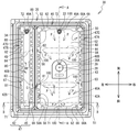
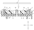
本発明の第二態様に係る印刷装置は、前記板状部材に設けられ、前記所定方向を向く第一面と、前記板状部材に設けられ、前記所定方向とは反対方向を向く第二面と、前記板状部材に設けられ、前記枠状壁部の前記内端面に対向し、前記第一面と前記第二面とを接続する第三面と、前記板状部材に設けられ、前記吸収部材と対向し、前記第一面と前記第二面とを接続する第四面と、前記第三面と前記第四面との間に亘って、前記第一面において前記第二面に向けて凹む第一凹部と、前記第一面と前記第二面との間に亘って、前記第三面において前記第四面に向けて凹む第二凹部との少なくとも一方を含む凹部とを備え、前記吸収部材の中央部には、前記キャップを保持する保持部材の筒状突出部が挿通される挿通孔が形成され、前記内端面に形成され、前記挿通孔の軸線から遠ざかる方向に凹む溝部を備えることを特徴とする。
11 ヘッド
11A 吐出面
29 吸引部
40 キャップ
42A,42B 吸引口
47A 第一枠状壁部
47B 第二枠状壁部
47C 第一内端面
47D 第二内端面
48,49 吸収部材
50,80 板状部材
51A 第一面
51B 第二面
51C 第三面
51D 第四面
69 露出凹部
71,72 第一凹部
81〜84 第二凹部
85 延出面
86B 傾斜面
100 凹部
111 ノズル
Claims (8)
- 複数のノズルが形成され、所定方向を向く吐出面を有するヘッドと、
弾性体によって形成される枠状壁部を有し、前記枠状壁部が前記吐出面に対して接離する方向に相対的に移動することにより、前記枠状壁部が前記複数のノズルを囲んで前記吐出面に接触可能に設けられたキャップと、
前記枠状壁部に囲まれる位置の前記キャップに形成された吸引口を介して前記キャップ内部と接続した吸引手段と、
前記枠状壁部に囲まれる位置に配置され、液体を吸収可能な吸収部材と、
前記枠状壁部に囲まれる位置に配置される部材であって、前記枠状壁部の内端面に沿って延びる基部を有し、前記吸引口が前記基部の内側に設けられる板状部材と、
前記基部に設けられ、前記所定方向を向く第一面と、
前記基部に設けられ、前記所定方向とは反対方向を向く第二面と、
前記基部に設けられ、前記枠状壁部の前記内端面に対向し、前記第一面と前記第二面とを接続する第三面と、
前記基部に設けられ、前記吸収部材と対向し、前記第一面と前記第二面とを接続する第四面と、
前記第三面と前記第四面との間に亘って、前記第一面において前記第二面に向けて凹む第一凹部と、前記第一面と前記第二面との間に亘って、前記第三面において前記第四面に向けて凹む第二凹部との少なくとも一方を含む凹部と、
前記第一面に接続し、且つ、前記第三面から前記第四面へ向かう第三方向に向かうにつれて前記所定方向に延びる傾斜面と
を備えたことを特徴とする印刷装置。 - 前記基部は、
前記所定方向と交差する第一方向に延びる第一延設部と、
前記所定方向と前記第一方向のそれぞれと交差する第二方向に延び、前記第二方向における長さが、前記第一延設部の前記第一方向における長さよりも長い第二延設部と
を備え、
前記凹部は、前記第二延設部に形成されたことを特徴とする請求項1に記載の印刷装置。 - 前記凹部は、前記第二延設部に複数形成されたことを特徴とする請求項2に記載の印刷装置。
- 前記凹部は、前記第二凹部を含み、
前記第二凹部は、前記吸引口からの離隔距離が互いに異なる二つの位置のそれぞれに設けられ、
前記二つの位置のうち前記離隔距離が長い方の位置である第一位置に設けられた前記第二凹部の深さは、前記二つの位置のうち前記離隔距離が短い方の位置である第二位置に設けられた前記第二凹部の深さ以上であることを特徴とする請求項1から3のいずれかに記載の印刷装置。 - 前記凹部は、前記第二凹部を含み、
前記第二凹部は、
前記第三方向へ前記第三面から延出する第一延出面と、
前記第一延出面に対して隙間を空けて対向し、前記第三面から前記第三方向へ延出する第二延出面とを備え、
前記傾斜面は、前記第一延出面、前記第二延出面、及び前記第一面に接続することを特徴とする請求項1から4のいずれかに記載の印刷装置。 - 前記凹部は、前記第一凹部を含み、
前記第一凹部は、前記第一延設部に形成されたことを特徴とする請求項2又は3に記載の印刷装置。 - 前記基部は、一対の前記第一延設部と、一対の前記第二延設部とから形成される枠であり、
前記凹部は、一対の前記第二延設部のそれぞれに形成され、
前記一対の第二延設部の一方に設けられた前記凹部の位置と、前記一対の第二延設部の他方に設けられた前記凹部の位置とは、互いに対称であることを特徴とする請求項2又は3に記載の印刷装置。 - 複数のノズルが形成され、所定方向を向く吐出面を有するヘッドと、
弾性体によって形成される枠状壁部を有し、前記枠状壁部が前記吐出面に対して接離する方向に相対的に移動することにより、前記枠状壁部が前記複数のノズルを囲んで前記吐出面に接触可能に設けられたキャップと、
前記枠状壁部に囲まれる位置の前記キャップに形成された吸引口を介して前記キャップ内部と接続した吸引手段と、
前記枠状壁部に囲まれる位置に配置され、液体を吸収可能な吸収部材と、
前記枠状壁部に囲まれる位置に配置され、前記枠状壁部の内端面に沿って延びる板状部材と、
前記板状部材に設けられ、前記所定方向を向く第一面と、
前記板状部材に設けられ、前記所定方向とは反対方向を向く第二面と、
前記板状部材に設けられ、前記枠状壁部の前記内端面に対向し、前記第一面と前記第二面とを接続する第三面と、
前記板状部材に設けられ、前記吸収部材と対向し、前記第一面と前記第二面とを接続する第四面と、
前記第三面と前記第四面との間に亘って、前記第一面において前記第二面に向けて凹む第一凹部と、前記第一面と前記第二面との間に亘って、前記第三面において前記第四面に向けて凹む第二凹部との少なくとも一方を含む凹部と
を備え、
前記吸収部材の中央部には、前記キャップを保持する保持部材の筒状突出部が挿通される挿通孔が形成され、
前記内端面に形成され、前記挿通孔の軸線から遠ざかる方向に凹む溝部を備えることを特徴とする印刷装置。
Priority Applications (1)
| Application Number | Priority Date | Filing Date | Title |
|---|---|---|---|
| US15/432,467 US9969170B2 (en) | 2016-02-16 | 2017-02-14 | Print device having maintenance mechanism for head unit |
Applications Claiming Priority (2)
| Application Number | Priority Date | Filing Date | Title |
|---|---|---|---|
| JP2016026780 | 2016-02-16 | ||
| JP2016026780 | 2016-02-16 |
Publications (2)
| Publication Number | Publication Date |
|---|---|
| JP2017144726A JP2017144726A (ja) | 2017-08-24 |
| JP6540726B2 true JP6540726B2 (ja) | 2019-07-10 |
Family
ID=59680582
Family Applications (1)
| Application Number | Title | Priority Date | Filing Date |
|---|---|---|---|
| JP2017020095A Active JP6540726B2 (ja) | 2016-02-16 | 2017-02-07 | 印刷装置 |
Country Status (1)
| Country | Link |
|---|---|
| JP (1) | JP6540726B2 (ja) |
Families Citing this family (4)
| Publication number | Priority date | Publication date | Assignee | Title |
|---|---|---|---|---|
| JP7028095B2 (ja) | 2018-07-26 | 2022-03-02 | ブラザー工業株式会社 | 画像記録装置 |
| JP7035887B2 (ja) | 2018-07-31 | 2022-03-15 | ブラザー工業株式会社 | 画像記録装置 |
| JP2020019200A (ja) | 2018-07-31 | 2020-02-06 | ブラザー工業株式会社 | 液体吐出装置、及び吐出制御方法 |
| JP7334400B2 (ja) | 2018-08-30 | 2023-08-29 | ブラザー工業株式会社 | 記録装置 |
Family Cites Families (6)
| Publication number | Priority date | Publication date | Assignee | Title |
|---|---|---|---|---|
| JPH1034944A (ja) * | 1996-07-22 | 1998-02-10 | Brother Ind Ltd | インクジェット記録装置 |
| JPH10264402A (ja) * | 1997-03-26 | 1998-10-06 | Seiko Epson Corp | インクジェット式記録ヘッドのキャッピング装置 |
| KR100542579B1 (ko) * | 2003-09-15 | 2006-01-11 | 삼성전자주식회사 | 잉크젯프린터용 프린트헤드의 캡핑장치 및 잉크젯프린터 |
| JP5444843B2 (ja) * | 2009-05-26 | 2014-03-19 | ブラザー工業株式会社 | インクジェット記録装置 |
| JP5220070B2 (ja) * | 2010-08-31 | 2013-06-26 | キヤノン株式会社 | インクジェット記録装置 |
| JP2016221783A (ja) * | 2015-05-28 | 2016-12-28 | キヤノン株式会社 | 記録装置及びキャップ |
-
2017
- 2017-02-07 JP JP2017020095A patent/JP6540726B2/ja active Active
Also Published As
| Publication number | Publication date |
|---|---|
| JP2017144726A (ja) | 2017-08-24 |
Similar Documents
| Publication | Publication Date | Title |
|---|---|---|
| US9969170B2 (en) | Print device having maintenance mechanism for head unit | |
| US8608279B2 (en) | Liquid jetting apparatus and cap member | |
| JP4513337B2 (ja) | インクカートリッジ | |
| CN109910440B (zh) | 罐以及液体喷射装置 | |
| JP6540726B2 (ja) | 印刷装置 | |
| JP2008221836A (ja) | 吐出ヘッドのキャップ装置および回復装置 | |
| JP6493784B2 (ja) | 印刷装置 | |
| JP5332887B2 (ja) | 流体噴射装置 | |
| US9050810B2 (en) | Image forming apparatus configured with recording head cap having plural release valves | |
| JP6540727B2 (ja) | 印刷装置 | |
| US9573376B2 (en) | Waste liquid recovery apparatus and liquid ejecting apparatus | |
| US11780236B2 (en) | Liquid ejecting apparatus and control method of liquid ejecting apparatus | |
| JP7621825B2 (ja) | 液体収容容器及び記録装置 | |
| JP4552505B2 (ja) | インクジェットプリンタ | |
| US9931846B2 (en) | Print device | |
| JP4951911B2 (ja) | 画像記録装置の輸送方法 | |
| JP2017136802A (ja) | 液体吐出装置 | |
| CN105383182B (zh) | 废墨回收单元、打印机以及废墨回收方法 | |
| JP7483961B2 (ja) | 記録装置 | |
| JP7472717B2 (ja) | 液体タンク、液体噴射装置 | |
| JP5532161B2 (ja) | 液体供給装置及び液体カートリッジ | |
| US8651636B2 (en) | Liquid droplet ejection apparatus | |
| JP4403790B2 (ja) | インクカートリッジ及びインクジェット記録装置 | |
| JP4691940B2 (ja) | 液体噴射装置 | |
| JP2017193148A (ja) | 液体吐出装置 |
Legal Events
| Date | Code | Title | Description |
|---|---|---|---|
| A621 | Written request for application examination |
Free format text: JAPANESE INTERMEDIATE CODE: A621 Effective date: 20180323 |
|
| A977 | Report on retrieval |
Free format text: JAPANESE INTERMEDIATE CODE: A971007 Effective date: 20181218 |
|
| A131 | Notification of reasons for refusal |
Free format text: JAPANESE INTERMEDIATE CODE: A131 Effective date: 20190122 |
|
| A521 | Written amendment |
Free format text: JAPANESE INTERMEDIATE CODE: A523 Effective date: 20190319 |
|
| TRDD | Decision of grant or rejection written | ||
| A01 | Written decision to grant a patent or to grant a registration (utility model) |
Free format text: JAPANESE INTERMEDIATE CODE: A01 Effective date: 20190514 |
|
| A61 | First payment of annual fees (during grant procedure) |
Free format text: JAPANESE INTERMEDIATE CODE: A61 Effective date: 20190527 |
|
| R150 | Certificate of patent or registration of utility model |
Ref document number: 6540726 Country of ref document: JP Free format text: JAPANESE INTERMEDIATE CODE: R150 |