JP6569112B1 - Flow rate detection device and flow rate detection method - Google Patents
Flow rate detection device and flow rate detection method Download PDFInfo
- Publication number
- JP6569112B1 JP6569112B1 JP2019101819A JP2019101819A JP6569112B1 JP 6569112 B1 JP6569112 B1 JP 6569112B1 JP 2019101819 A JP2019101819 A JP 2019101819A JP 2019101819 A JP2019101819 A JP 2019101819A JP 6569112 B1 JP6569112 B1 JP 6569112B1
- Authority
- JP
- Japan
- Prior art keywords
- light
- rotating body
- flow rate
- parallel light
- rate detection
- Prior art date
- Legal status (The legal status is an assumption and is not a legal conclusion. Google has not performed a legal analysis and makes no representation as to the accuracy of the status listed.)
- Active
Links
Images




Landscapes
- Measuring Volume Flow (AREA)
Abstract
【課題】流体の流れに応じて平面上で回転する回転体の回転数を検出する場合でも、投光手段の位置合わせについてロバスト性を有する流量検出装置及び流量検出方法を提供する。【解決手段】上記課題を解決するため、流体の流れに応じて平面上で回転する回転体11の回転数を検出する流量検出装置1であって、上記回転体11へ向けて平行光を発する投光部3と、回転体11で反射された平行光における光路の変化を検知する受光部4と、投光部3と回転体11との間に配置され、上記平面に対する入射角が90度より小さな正の角度となるよう上記平行光を屈折させると共に、上記反射された平行光を受光部4へ受光させる光路変更部5とを備えた流量検出装置1を提供する。【選択図】図1Provided are a flow rate detection device and a flow rate detection method that have robustness for alignment of light projecting means even when detecting the number of rotations of a rotating body that rotates on a plane according to the flow of fluid. In order to solve the above problems, a flow rate detection device 1 for detecting the number of rotations of a rotating body 11 rotating on a plane according to the flow of a fluid, emits parallel light toward the rotating body 11. The light projecting unit 3, the light receiving unit 4 that detects a change in the optical path of the parallel light reflected by the rotating body 11, and the light projecting unit 3 and the rotating body 11 are disposed between the light projecting unit 3 and the rotating body 11. Provided is a flow rate detection device 1 including an optical path changing unit 5 that refracts the parallel light so as to have a smaller positive angle and receives the reflected parallel light to a light receiving unit 4. [Selection] Figure 1
Description
本発明は、水道管等を流れる水等の流体の流量を検出する技術に関するものである。 The present invention relates to a technique for detecting the flow rate of a fluid such as water flowing through a water pipe or the like.
水道メータが出荷される際には、水道メータに設けられたパイロットに光を当てて反射光を検知し、上記パイロットの回転数を検出することによって、上記水道メータの計量値を計測するといった検査が行われている。本検査において用いられる装置や方法は、例えば以下の特許文献1に開示されている。
When a water meter is shipped, an inspection is performed in which the measured value of the water meter is measured by irradiating a pilot provided in the water meter to detect reflected light and detecting the number of revolutions of the pilot. Has been done. The apparatus and method used in this inspection are disclosed in, for example,
特許文献1に開示された流量検出装置1では、同文献の段落[0024]に記載されているように、八面体からなる通水パイロット92の直上からその直径より大きな径を持つ光線が照射されるため、検査の際にたとえ投光部2の位置が通水パイロット92の直上から多少ずれた場合でも上記反射光の検知に影響を与えないという堅牢性(ロバスト性)が実現されている。
In the flow
しかし、上記パイロットが、特許文献1に開示された上記のような多面体からなるもの(以下、「多面体パイロット」という。)ではなく、図6(a),(b)に示されるような平面反射板11bの上で中心軸11cの周りに回転する平面形状の羽根車11aからなるもの(以下、「平面反射パイロット」という。)である場合には、上記ロバスト性の実現は容易でないという課題がある。なお、図6においては、羽根車11aは黒塗りで表示されている(図1でも同じ)。 However, the pilot is not composed of the polyhedron as disclosed above in Patent Document 1 (hereinafter referred to as “polyhedron pilot”), but planar reflection as shown in FIGS. 6 (a) and 6 (b). If the plate 11b is composed of a planar impeller 11a rotating around the central axis 11c (hereinafter referred to as “planar reflection pilot”), the above-described robustness is not easy to realize. is there. In FIG. 6, the impeller 11a is displayed in black (the same applies to FIG. 1).
すなわち、上記と同様に平面反射パイロット11の直上からその直径より大きな径を持つ光線を照射した場合には、多面体パイロットと異なり平面反射板11bで反射するため、検知する反射光全体の輝度は羽根車11aの回転により変化しない。
That is, in the same way as described above, when a light beam having a diameter larger than the diameter is irradiated from directly above the
一方、平面反射パイロット11へ照射する光線の径を小さくすれば、投光手段の平面反射パイロット11に対する位置合わせに正確性が要求されることになる。
On the other hand, if the diameter of the light beam applied to the
本発明は、上記のような課題を解決するためになされたもので、流体の流れに応じて平面上で回転する回転体の回転数を検出する場合でも、投光手段の位置合わせについてロバスト性を有する流量検出装置及び流量検出方法を提供することを目的とする。 The present invention has been made in order to solve the above-described problems. Even when detecting the number of rotations of a rotating body that rotates on a plane according to the flow of fluid, the present invention is robust with respect to alignment of the light projecting means. An object of the present invention is to provide a flow rate detection device and a flow rate detection method having
本発明は上記課題を解決するため、流体の流れに応じて平面上で回転する回転体の回転数を検出する流量検出装置であって、上記回転体へ向けて平行光を発する投光手段と、上記回転体で反射された平行光における光路の変化を検知する受光手段と、投光手段と上記回転体との間に配置され、上記平面に対する入射角が90度より小さな正の角度となるよう上記平行光を屈折させると共に、上記反射された平行光を受光手段へ受光させる光路変更手段とを備えた流量検出装置を提供する。 In order to solve the above-mentioned problem, the present invention is a flow rate detection device that detects the number of rotations of a rotating body that rotates on a plane according to the flow of fluid, and a light projecting unit that emits parallel light toward the rotating body; A light receiving means for detecting a change in the optical path of the parallel light reflected by the rotating body, and a light receiving means disposed between the light projecting means and the rotating body, and the incident angle with respect to the plane is a positive angle smaller than 90 degrees. A flow rate detecting device is provided that includes an optical path changing unit that refracts the parallel light and receives the reflected parallel light to a light receiving unit.
また、本発明は上記課題を解決するため、流体の流れに応じて平面上で回転する回転体の回転数を検出する流量検出方法であって、投光手段に上記回転体へ向けて平行光を投光させる第1のステップと、光路変更手段に上記平行光を上記平面に対する入射角が90度より小さな正の角度となるよう屈折させて上記回転体に照射させる第2のステップと、受光手段に上記回転体で反射された平行光における光路の変化を検知させる第3のステップを有する流量検出方法を提供する。 In order to solve the above-mentioned problem, the present invention is a flow rate detection method for detecting the number of rotations of a rotating body that rotates on a plane in accordance with the flow of a fluid. A second step of causing the optical path changing means to refract the parallel light so that the incident angle with respect to the plane is a positive angle smaller than 90 degrees and irradiate the rotating body; There is provided a flow rate detection method comprising a third step of causing a means to detect a change in the optical path of parallel light reflected by the rotating body.
本発明によれば、流体の流れに応じて平面上で回転する回転体の回転数を検出する場合でも、投光手段の位置合わせについてロバスト性を有する流量検出装置及び流量検出方法を提供することができる。 According to the present invention, it is possible to provide a flow rate detection device and a flow rate detection method that have robustness with respect to alignment of the light projecting means even when the number of rotations of a rotating body that rotates on a plane according to the flow of fluid is detected. Can do.
以下において、本発明の実施の形態を図面を参照しつつ詳しく説明する。なお、図中同一符号は同一又は相当部分を示す。 Hereinafter, embodiments of the present invention will be described in detail with reference to the drawings. In the drawings, the same reference numerals indicate the same or corresponding parts.
図1は、本発明の実施の形態に係る流量検出装置1の構成を示す図である。図1に示されるように、本発明の実施の形態に係る流量検出装置1は、水などの流体の流量を計測する水道メータ10に設けられ、上記流体の流れに応じて平面反射板11bの上で回転する平面状の羽根車11aからなる平面反射パイロット11の回転数を検出する流量検出装置1であって、平面反射パイロット11へ向けて平行光を発する投光部3と、平面反射板11bで反射された上記平行光における光路の変化を検知する受光部4と、投光部3と平面反射パイロット11との間に配置され、平面反射板11bに対する入射角が90度より小さな正の角度となるよう上記平行光を屈折させると共に、平面反射板11bで反射された上記平行光を受光部4へ受光させる光路変更部5とを備える。なお、受光部4は後述する受光センサ4a,4bを含む。
FIG. 1 is a diagram showing a configuration of a flow
ここで、例えば、投光部3と受光部4を共通の筐体に格納して流量計測部2を構成すると共に、光路変更部5を上記筐体とは別体として構成することにより、検査対象とする水道メータ10に対して光路変更部5を着脱可能としても良い。なお、このような構成とした場合のメリットについては後述する。
Here, for example, the
また、光路変更部5は、円形の凸レンズを任意の直径に沿って切断した一方が、上記凸レンズの光軸が平面反射パイロット11へ向けて発せられる上記平行光の進行方向と一致するよう配置された半円レンズ7と、平面反射板11bで反射された上記平行光を受光部4へ直射させる間隙部6とを含む。なお、図1において、半円レンズ7は横縞模様で表示され(図2でも同じ)、間隙部6は網目模様で表示されている。
The optical
ここで、図2に示されるように、間隙部6はレンズホルダLHの底面に設けられた円形などの孔からなり、半円レンズ7はこの孔のおよそ半分の領域を覆うようにレンズホルダLHに載置される。なお、図2においては、上記のように凸レンズを任意の直径に沿って切断して得られる半円レンズ7の断面が縦縞模様で表示されている。
Here, as shown in FIG. 2, the
光路変更部5は、このような構成を有することにより、半円レンズ7で受光した平行光を集光して平面反射パイロット11へ照射すると共に、平面反射板11bで反射された上記平行光をレンズで再度集光することなく間隙部6を通過させて受光部4へ直接検知させる作用を奏する。
By having such a configuration, the optical
ここで、半円レンズ7によれば、受光した平行光を集光することにより、平面反射パイロット11へ照射する光の輝度を上げ、その結果として当該反射光の輝度も上げることができるため、受光部4における検知における信号対雑音比(S/N比)を向上させて検知の信頼性を高める効果を得ることができる。
Here, according to the
また、間隙部6によれば、通過させる平面反射板11bで反射された上記平行光は発散光となり、形成される像は平面反射板11bからの距離に比例して拡大されるため、受光部4までの距離を大きくとることによって上記受光センサ4a,4bの構造設計を容易にすることができるという効果を得ることができる。
Further, according to the
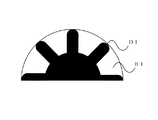
そして、間隙部6を通過した上記平行光は受光部4において、図3に示されるように、羽根車11aの各羽根で遮光されることにより形成される影部DIと、隣り合う羽根の間を透過する光により形成される明部BIが円弧上に交互に並んだ像を形成する。
Then, as shown in FIG. 3, the parallel light that has passed through the
ここで、半円レンズ7は、受光した平行光を羽根車11aの平面反射板11b上における回転領域の半分を覆うよう集光する機能を有すれば好適である。半円レンズ7がこのような機能を有すれば、平面反射板11bで反射された上記平行光により、受光部4において図3に示される像、すなわち、上記回転領域の半分に対する像が形成される。
Here, it is preferable that the
次に、本発明の実施の形態に係る流量検出方法について、上記のような構成を有する流量検出装置1の動作により実現する場合を例に挙げて説明する。なお、本流量検出方法は上記流量検出装置1を用いる場合に限られないことは言うまでもない。
Next, the flow rate detection method according to the embodiment of the present invention will be described taking as an example a case where the flow rate detection method is realized by the operation of the flow
第1のステップでは、投光部3に、平面反射パイロット11へ向けて平行光を投光させる。第2のステップでは、光路変更部5に、上記平行光を平面反射板11bに対する入射角が90度より小さな正の角度となるよう屈折させて平面反射パイロット11に照射させる。第3のステップでは、受光部4に、平面反射パイロット11で反射された平行光における光路の変化を検知させる。
In the first step, the
ここで、図4に示されるように、受光部4に結像した明部BIは、羽根車11aの回転に伴って例えば矢印の向きに回転する。このため、第3のステップにおける受光部4による検知は、互いに離隔した二つの受光センサ4a,4bを明部BIが横切る際に生じる輝度の変化をこれらの受光センサ4a,4bで同時的にセンシングし差動を得ることにより実現される。
Here, as shown in FIG. 4, the bright part BI imaged on the
なお、このような差動を得ることにより回転体の回転数を計測する技術については、特許文献1の図6及びその説明箇所などにおいて既に開示されているので説明を割愛する。 Note that a technique for measuring the number of rotations of the rotating body by obtaining such a differential has already been disclosed in FIG.
このような流量検出方法によれば、平行光を平面反射板11bに対する入射角が90度より小さな正の角度となるよう屈折させて平面反射パイロット11に照射させることにより、たとえ上記平行光が平面反射板11bで反射される場合であっても、多面体パイロット12を検査対象とした図5からも容易に分かるように、傾斜角を有する反射面で受光した光を反射させる多面体パイロット12へ直上から平行光を当てた場合と物理的に等価な作用を生じさせることができる。
According to such a flow rate detection method, the parallel light is refracted so that the incident angle with respect to the flat reflecting plate 11b becomes a positive angle smaller than 90 degrees and is irradiated to the flat reflecting
このため、投光部3から多面体パイロット12へ平行光を照射する場合に、投光部3が多面体パイロット12の直上から多少ずれたときでも受光部4による検知結果に与える影響を小さくできるといった位置合わせにおけるロバスト性を、検査対象が平面反射パイロット11である場合においても実現することができる。
For this reason, when irradiating parallel light from the
このとき、光路変更部5に、受光した平行光を羽根車11aの平面反射板11b上における回転領域の半分を覆うよう集光させるようにすれば好適である。
At this time, it is preferable that the optical
このように集光された範囲内で平面反射パイロット11の位置がずれても、受光部4による当該反射光の検知に全く影響を与えないようにすることができるためである。
This is because even if the position of the
また、第3のステップにおいて、受光部4に、平面反射パイロット11で反射された平行光を直接検知させると好適である。上記のように、受光部4の構造設計を容易にすることができるためである。
In the third step, it is preferable that the
なお、上記において、図6に示された平面反射パイロット11は、平面反射板11bではなく羽根車11aの表面において光を反射する構造であっても良い。この場合には、図3の影部DIと明部BIが入れ替わることになるに過ぎず、流量検出装置1は上記と同様に動作することができる。
In the above, the
以上のように、本発明の実施の形態に係る流量検出装置1及び流量検出方法によれば、水などの流体の流れに応じて平面反射板11bの上で回転する羽根車11aからなる平面反射パイロット11の回転数を検出する場合に、たとえ投光部3が平面反射パイロット11の直上からずれた場合においても受光部4による当該反射光の検知結果に与える影響を小さくできるといった位置合わせにおけるロバスト性を有する流量検出装置1及び流量検出方法を提供することができる。
As described above, according to the flow
また、図5に示されるように、多面体パイロット12を有する水道メータ10を検査対象とする場合には、図1に示された流量検出装置1から光路変更部5を取り外して流量計測部2を用いて多面体パイロット12の回転数を検出することにより、投光部3が多面体パイロット12の直上からずれたときでも受光部4による当該反射光の検知結果に与える影響を小さくできるといった位置合わせにおけるロバスト性を実現することもできる。
Further, as shown in FIG. 5, when the
1 流量検出装置、2 流量計測部、3 投光部、4 受光部、5 光路変更部、6 間隙部、7 半円レンズ、11 平面反射パイロット、11a 羽根車、11b 平面反射板。
DESCRIPTION OF
Claims (5)
前記回転体へ向けて平行光を発する投光手段と、
前記回転体で反射された前記平行光における光路の変化を検知する受光手段と、
前記投光手段と前記回転体との間に配置され、前記平面に対する入射角が90度より小さな正の角度となるよう前記平行光を屈折させると共に、前記反射された前記平行光を前記受光手段へ受光させるものであり、
円形の凸レンズを任意の直径に沿って切断した一方が、前記凸レンズの光軸が前記回転体へ向けて発せられる前記平行光の進行方向と一致するよう配置された半円レンズと、
前記反射された前記平行光を前記受光手段へ直射させる間隙部を含む光路変更手段とを備えた流量検出装置。 A flow rate detection device that detects the number of rotations of a rotating body that rotates on a plane according to the flow of fluid,
A light projecting means for emitting parallel light toward the rotating body;
A light receiving means for detecting a change in an optical path in the parallel light reflected by the rotating body;
The parallel light is disposed between the light projecting means and the rotating body, refracts the parallel light so that the incident angle with respect to the plane is a positive angle smaller than 90 degrees, and the reflected parallel light is received by the light receiving means. To receive light ,
A semicircular lens arranged such that one of the circular convex lenses is cut along an arbitrary diameter, and the optical axis of the convex lens coincides with the traveling direction of the parallel light emitted toward the rotating body;
A flow rate detection device comprising: an optical path changing unit including a gap portion that directly reflects the reflected parallel light onto the light receiving unit .
投光手段に、前記回転体へ向けて平行光を投光させる第1のステップと、
光路変更手段に、前記平行光を前記平面に対する入射角が90度より小さな正の角度となるよう屈折させて前記回転体に照射させると共に、受光した前記平行光を前記回転体の前記平面上における回転領域の半分を覆うよう集光させる第2のステップと、
受光手段に、前記回転体で反射された前記平行光における光路の変化を検知させる第3のステップを有する流量検出方法。 A flow rate detection method for detecting the number of rotations of a rotating body that rotates on a plane according to the flow of fluid,
A first step of causing the light projecting means to project parallel light toward the rotating body;
The optical path changing unit refracts the parallel light so that the incident angle with respect to the plane is a positive angle smaller than 90 degrees and irradiates the rotating body, and receives the received parallel light on the plane of the rotating body. A second step of collecting light to cover half of the rotation area ;
A flow rate detection method comprising a third step of causing a light receiving means to detect a change in an optical path in the parallel light reflected by the rotating body.
The flow rate detection method according to claim 4 , wherein in the third step, the light receiving unit directly detects the parallel light reflected by the rotating body.
Priority Applications (1)
| Application Number | Priority Date | Filing Date | Title |
|---|---|---|---|
| JP2019101819A JP6569112B1 (en) | 2019-05-30 | 2019-05-30 | Flow rate detection device and flow rate detection method |
Applications Claiming Priority (1)
| Application Number | Priority Date | Filing Date | Title |
|---|---|---|---|
| JP2019101819A JP6569112B1 (en) | 2019-05-30 | 2019-05-30 | Flow rate detection device and flow rate detection method |
Publications (2)
| Publication Number | Publication Date |
|---|---|
| JP6569112B1 true JP6569112B1 (en) | 2019-09-04 |
| JP2020197385A JP2020197385A (en) | 2020-12-10 |
Family
ID=67844769
Family Applications (1)
| Application Number | Title | Priority Date | Filing Date |
|---|---|---|---|
| JP2019101819A Active JP6569112B1 (en) | 2019-05-30 | 2019-05-30 | Flow rate detection device and flow rate detection method |
Country Status (1)
| Country | Link |
|---|---|
| JP (1) | JP6569112B1 (en) |
Families Citing this family (1)
| Publication number | Priority date | Publication date | Assignee | Title |
|---|---|---|---|---|
| JP7818896B2 (en) | 2020-11-27 | 2026-02-24 | 三菱重工エンジン&ターボチャージャ株式会社 | Austenitic stainless steel cast and method for manufacturing austenitic stainless steel cast |
Family Cites Families (4)
| Publication number | Priority date | Publication date | Assignee | Title |
|---|---|---|---|---|
| JP3053442B2 (en) * | 1991-01-16 | 2000-06-19 | 愛知時計電機株式会社 | Pilot rotation detector for water meter |
| JP2002107190A (en) * | 2000-10-03 | 2002-04-10 | Junichi Shizuma | Apparatus which is installed in mechanically integrating flow meter and outputs electric pulse signal proportional to flow rate |
| JP2013003032A (en) * | 2011-06-20 | 2013-01-07 | Hochiki Corp | Water meter-based detecting device |
| JP5396590B1 (en) * | 2013-07-01 | 2014-01-22 | サイトー技研株式会社 | Flow rate detection device and flow rate detection method |
-
2019
- 2019-05-30 JP JP2019101819A patent/JP6569112B1/en active Active
Also Published As
| Publication number | Publication date |
|---|---|
| JP2020197385A (en) | 2020-12-10 |
Similar Documents
| Publication | Publication Date | Title |
|---|---|---|
| JP5721070B2 (en) | Optical property measuring device | |
| US10533939B2 (en) | Gas detection device | |
| CN111257848B (en) | Large field of view measurement equipment for LIDAR | |
| JP2016090584A (en) | Sensor | |
| KR101026030B1 (en) | Distance measuring device | |
| US7433052B2 (en) | Systems and methods for tilt and range measurement | |
| JP6569112B1 (en) | Flow rate detection device and flow rate detection method | |
| JP6807448B2 (en) | Scanning reflector amplitude measuring device and measuring method | |
| JP2008517283A (en) | Improved measurement system | |
| JP5337419B2 (en) | Displacement measuring device, seal member shape measuring device using the same, and displacement detecting device used therefor | |
| JP2008175604A (en) | Optical displacement sensor and displacement measuring device using it | |
| JP2008196855A (en) | Wafer positioning method and positioning apparatus | |
| US10054538B1 (en) | Gas detection device | |
| JP2010216922A (en) | Optical displacement meter and optical displacement measurement method | |
| RU2270979C2 (en) | Device for determination of inner surface contour of object | |
| JP3276577B2 (en) | Optical surface roughness measuring device | |
| JP7078115B2 (en) | Light scattering detector | |
| JP3479914B1 (en) | Tilt detector | |
| TW201807431A (en) | Optical detecting device capable of determining relative position of a reference object or a light source | |
| JP7187874B2 (en) | light scattering detector | |
| JP5054318B2 (en) | Displacement sensor, shape measuring device | |
| JP3672562B2 (en) | Lens meter | |
| CN112697039B (en) | A detection device and a detection equipment | |
| KR102600032B1 (en) | Inspection automatic apparatus and module for agricultural products and livestock products | |
| RU45520U1 (en) | LASER TRIANGULATION METER |
Legal Events
| Date | Code | Title | Description |
|---|---|---|---|
| A621 | Written request for application examination |
Free format text: JAPANESE INTERMEDIATE CODE: A621 Effective date: 20190530 |
|
| A871 | Explanation of circumstances concerning accelerated examination |
Free format text: JAPANESE INTERMEDIATE CODE: A871 Effective date: 20190530 |
|
| A975 | Report on accelerated examination |
Free format text: JAPANESE INTERMEDIATE CODE: A971005 Effective date: 20190605 |
|
| A131 | Notification of reasons for refusal |
Free format text: JAPANESE INTERMEDIATE CODE: A131 Effective date: 20190618 |
|
| A521 | Request for written amendment filed |
Free format text: JAPANESE INTERMEDIATE CODE: A523 Effective date: 20190625 |
|
| TRDD | Decision of grant or rejection written | ||
| A01 | Written decision to grant a patent or to grant a registration (utility model) |
Free format text: JAPANESE INTERMEDIATE CODE: A01 Effective date: 20190709 |
|
| A61 | First payment of annual fees (during grant procedure) |
Free format text: JAPANESE INTERMEDIATE CODE: A61 Effective date: 20190711 |
|
| R150 | Certificate of patent or registration of utility model |
Ref document number: 6569112 Country of ref document: JP Free format text: JAPANESE INTERMEDIATE CODE: R150 |
|
| R250 | Receipt of annual fees |
Free format text: JAPANESE INTERMEDIATE CODE: R250 |
|
| R250 | Receipt of annual fees |
Free format text: JAPANESE INTERMEDIATE CODE: R250 |
|
| R250 | Receipt of annual fees |
Free format text: JAPANESE INTERMEDIATE CODE: R250 |
|
| R250 | Receipt of annual fees |
Free format text: JAPANESE INTERMEDIATE CODE: R250 |