JP6578838B2 - 真空ポンプおよび質量分析装置 - Google Patents
真空ポンプおよび質量分析装置 Download PDFInfo
- Publication number
- JP6578838B2 JP6578838B2 JP2015181787A JP2015181787A JP6578838B2 JP 6578838 B2 JP6578838 B2 JP 6578838B2 JP 2015181787 A JP2015181787 A JP 2015181787A JP 2015181787 A JP2015181787 A JP 2015181787A JP 6578838 B2 JP6578838 B2 JP 6578838B2
- Authority
- JP
- Japan
- Prior art keywords
- vacuum pump
- pump
- screw
- intake port
- stage
- Prior art date
- Legal status (The legal status is an assumption and is not a legal conclusion. Google has not performed a legal analysis and makes no representation as to the accuracy of the status listed.)
- Active
Links
Images


Classifications
-
- F—MECHANICAL ENGINEERING; LIGHTING; HEATING; WEAPONS; BLASTING
- F04—POSITIVE - DISPLACEMENT MACHINES FOR LIQUIDS; PUMPS FOR LIQUIDS OR ELASTIC FLUIDS
- F04D—NON-POSITIVE-DISPLACEMENT PUMPS
- F04D29/00—Details, component parts, or accessories
- F04D29/40—Casings; Connections of working fluid
- F04D29/52—Casings; Connections of working fluid for axial pumps
- F04D29/522—Casings; Connections of working fluid for axial pumps especially adapted for elastic fluid pumps
-
- F—MECHANICAL ENGINEERING; LIGHTING; HEATING; WEAPONS; BLASTING
- F04—POSITIVE - DISPLACEMENT MACHINES FOR LIQUIDS; PUMPS FOR LIQUIDS OR ELASTIC FLUIDS
- F04D—NON-POSITIVE-DISPLACEMENT PUMPS
- F04D19/00—Axial-flow pumps
- F04D19/02—Multi-stage pumps
- F04D19/04—Multi-stage pumps specially adapted to the production of a high vacuum, e.g. molecular pumps
- F04D19/042—Turbomolecular vacuum pumps
-
- F—MECHANICAL ENGINEERING; LIGHTING; HEATING; WEAPONS; BLASTING
- F04—POSITIVE - DISPLACEMENT MACHINES FOR LIQUIDS; PUMPS FOR LIQUIDS OR ELASTIC FLUIDS
- F04D—NON-POSITIVE-DISPLACEMENT PUMPS
- F04D19/00—Axial-flow pumps
- F04D19/02—Multi-stage pumps
- F04D19/04—Multi-stage pumps specially adapted to the production of a high vacuum, e.g. molecular pumps
- F04D19/044—Holweck-type pumps
-
- F—MECHANICAL ENGINEERING; LIGHTING; HEATING; WEAPONS; BLASTING
- F04—POSITIVE - DISPLACEMENT MACHINES FOR LIQUIDS; PUMPS FOR LIQUIDS OR ELASTIC FLUIDS
- F04D—NON-POSITIVE-DISPLACEMENT PUMPS
- F04D29/00—Details, component parts, or accessories
- F04D29/40—Casings; Connections of working fluid
- F04D29/52—Casings; Connections of working fluid for axial pumps
- F04D29/54—Fluid-guiding means, e.g. diffusers
- F04D29/541—Specially adapted for elastic fluid pumps
- F04D29/545—Ducts
-
- H—ELECTRICITY
- H01—ELECTRIC ELEMENTS
- H01J—ELECTRIC DISCHARGE TUBES OR DISCHARGE LAMPS
- H01J49/00—Particle spectrometers or separator tubes
- H01J49/02—Details
- H01J49/24—Vacuum systems, e.g. maintaining desired pressures
-
- H—ELECTRICITY
- H01—ELECTRIC ELEMENTS
- H01J—ELECTRIC DISCHARGE TUBES OR DISCHARGE LAMPS
- H01J49/00—Particle spectrometers or separator tubes
- H01J49/26—Mass spectrometers or separator tubes
-
- F—MECHANICAL ENGINEERING; LIGHTING; HEATING; WEAPONS; BLASTING
- F05—INDEXING SCHEMES RELATING TO ENGINES OR PUMPS IN VARIOUS SUBCLASSES OF CLASSES F01-F04
- F05B—INDEXING SCHEME RELATING TO WIND, SPRING, WEIGHT, INERTIA OR LIKE MOTORS, TO MACHINES OR ENGINES FOR LIQUIDS COVERED BY SUBCLASSES F03B, F03D AND F03G
- F05B2240/00—Components
- F05B2240/10—Stators
- F05B2240/12—Fluid guiding means, e.g. vanes
-
- F—MECHANICAL ENGINEERING; LIGHTING; HEATING; WEAPONS; BLASTING
- F05—INDEXING SCHEMES RELATING TO ENGINES OR PUMPS IN VARIOUS SUBCLASSES OF CLASSES F01-F04
- F05B—INDEXING SCHEME RELATING TO WIND, SPRING, WEIGHT, INERTIA OR LIKE MOTORS, TO MACHINES OR ENGINES FOR LIQUIDS COVERED BY SUBCLASSES F03B, F03D AND F03G
- F05B2240/00—Components
- F05B2240/20—Rotors
- F05B2240/24—Rotors for turbines
-
- F—MECHANICAL ENGINEERING; LIGHTING; HEATING; WEAPONS; BLASTING
- F05—INDEXING SCHEMES RELATING TO ENGINES OR PUMPS IN VARIOUS SUBCLASSES OF CLASSES F01-F04
- F05B—INDEXING SCHEME RELATING TO WIND, SPRING, WEIGHT, INERTIA OR LIKE MOTORS, TO MACHINES OR ENGINES FOR LIQUIDS COVERED BY SUBCLASSES F03B, F03D AND F03G
- F05B2240/00—Components
- F05B2240/50—Bearings
- F05B2240/51—Bearings magnetic
- F05B2240/511—Bearings magnetic with permanent magnets
-
- F—MECHANICAL ENGINEERING; LIGHTING; HEATING; WEAPONS; BLASTING
- F05—INDEXING SCHEMES RELATING TO ENGINES OR PUMPS IN VARIOUS SUBCLASSES OF CLASSES F01-F04
- F05B—INDEXING SCHEME RELATING TO WIND, SPRING, WEIGHT, INERTIA OR LIKE MOTORS, TO MACHINES OR ENGINES FOR LIQUIDS COVERED BY SUBCLASSES F03B, F03D AND F03G
- F05B2260/00—Function
- F05B2260/20—Heat transfer, e.g. cooling
- F05B2260/221—Improvement of heat transfer
- F05B2260/224—Improvement of heat transfer by increasing the heat transfer surface
- F05B2260/2241—Improvement of heat transfer by increasing the heat transfer surface using fins or ribs
Landscapes
- Engineering & Computer Science (AREA)
- Mechanical Engineering (AREA)
- General Engineering & Computer Science (AREA)
- Chemical & Material Sciences (AREA)
- Analytical Chemistry (AREA)
- Non-Positive Displacement Air Blowers (AREA)
- Other Investigation Or Analysis Of Materials By Electrical Means (AREA)
Description
さらに好ましい実施形態では、前記ガス通路は、前記円筒状ステータの外周面に形成された溝および前記円筒状ステータの外周側を覆うように設けられたポンプハウジングの内周面に形成された溝の少なくとも一方を含む。
さらに好ましい実施形態では、前記ガス通路は、前記貫通孔の開口の全域に対向するように形成されている。
本発明の好ましい実施形態による質量分析装置は、上記の真空ポンプと、第1の分析ユニットと、前記第1の分析ユニットよりも高い圧力領域で動作する第2の分析ユニットと、前記第1の分析ユニットが収納され、前記真空ポンプの第1吸気口が接続される第1排気口を有する第1チャンバと、前記第2の分析ユニットが収納され、前記真空ポンプの第2吸気口が接続される第2排気口を有する第2チャンバと、を備える。
−第1の実施の形態−
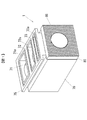
図1は、本発明に係る真空ポンプの一実施の形態を示す外観斜視図である。真空ポンプ1は、第1ハウジング70と第2ハウジング80とを備えている。第1ハウジング70には、第1吸気口71、第2吸気口72および第3吸気口73が形成されたフランジ部75が設けられている。第1吸気口71、第2吸気口72および第3吸気口73には、それぞれシールリングが装着されるシールリング溝71a,72a,73aが形成されている。第2ハウジング80には後述するようにモータが設けられ、第2ハウジング80の表面(真空ポンプ1の底面)には放熱フィン86が形成されている。
振れ回りを規制する規制部材として機能する。
図8は、本発明に係る真空ポンプの第2の実施の形態を示す図である。上述した第1の実施の形態ではガス通路700,701を第1ハウジング70の内周面に形成したが、第2の実施の形態では、ガス通路を第1ネジステータ60の外周面に形成するようにした。図8(a)に示す例では、第1ネジステータ60には第3吸気口73と対向するように設けられた貫通孔60aと、それと位相が180度異なる貫通孔60bとが形成されている。そして、第1ネジステータ60の外周面には、第3吸気口73と貫通孔60bとを接続するガス通路60G1,60G2が形成されている。
図11は、3つの吸気口71〜73を備える真空ポンプ1が搭載される質量分析装置100の一例を示す図である。図11は、エレクトロスプレーイオン化法(ESI)を用いた液体クロマトグラフ質量分析装置の概略構成を示す模式図である。質量分析装置100は、イオン化室150と質量分析部110とを備えている。質量分析部110には、イオン化室150に隣接する第1中間室113と、第1中間室に隣接する第2中間室114と、第2中間室114に隣接する分析室115とがそれぞれ隔壁を介して設けられている。
(1)真空ポンプ1は、図2,4,5に示すように、複数の吸気口(第1吸気口71,第2吸気口72および第3吸気口73)を備え、円筒状の第1ネジステータ60には、第1ネジステータ60を貫通して内周面に形成されたネジ溝GL3〜GL7と連通する貫通孔60aが形成されている。そして、貫通孔60aの周方向寸法L2は、第1ネジステータ60の外周面における第3吸気口73が対向する領域の周方向寸法L1以上に設定されている。さらに、貫通孔が貫通し且つ第3吸気口73が対向しないネジ溝GL3,GL7に、第3吸気口73から流入したガスを導くガス通路700を備えるようにした。
Claims (4)
- 第1ポンプステージと、
前記第1ポンプステージよりもポンプ下流側に設けられ、ネジ溝とネジ山とが内周面周方向に交互に複数形成された円筒状ステータ、および、前記円筒状ステータの内周側に設けられた円筒状ロータを有する第2ポンプステージと、
前記第1ポンプステージよりも上流側に設けられた第1吸気口と、
前記第1ポンプステージよりも下流側に設けられ、前記第2ポンプステージに連通する第2吸気口と、を備える真空ポンプであって、
前記円筒状ステータには、該円筒状ステータを貫通して内周面に形成された一以上の前記ネジ溝と連通する貫通孔が一以上形成され、
前記円筒状ステータに形成された前記一以上の貫通孔の各周方向寸法の合計は、前記円筒状ステータの外周面における前記第2吸気口が対向する領域の周方向寸法以上に設定され、
前記貫通孔が貫通し且つ前記第2吸気口が対向する領域から外れたネジ溝に、前記第2吸気口から流入したガスを導くガス通路を備える、真空ポンプ。 - 請求項1に記載の真空ポンプにおいて、
前記ガス通路は、前記円筒状ステータの外周面に形成された溝および前記円筒状ステータの外周側を覆うように設けられたポンプハウジングの内周面に形成された溝の少なくとも一方を含む、真空ポンプ。 - 請求項1または2に記載の真空ポンプにおいて、
前記ガス通路は、前記貫通孔の開口の全域に対向するように形成されている、真空ポンプ。 - 請求項1乃至3のいずれか一項に記載の真空ポンプと、
第1の分析ユニットと、
前記第1の分析ユニットよりも高い圧力領域で動作する第2の分析ユニットと、
前記第1の分析ユニットが収納され、前記真空ポンプの第1吸気口が接続される第1排気口を有する第1チャンバと、
前記第2の分析ユニットが収納され、前記真空ポンプの第2吸気口が接続される第2排気口を有する第2チャンバと、を備える質量分析装置。
Priority Applications (3)
| Application Number | Priority Date | Filing Date | Title |
|---|---|---|---|
| JP2015181787A JP6578838B2 (ja) | 2015-09-15 | 2015-09-15 | 真空ポンプおよび質量分析装置 |
| CN201610621779.8A CN106523394B (zh) | 2015-09-15 | 2016-08-01 | 真空泵及质量分析装置 |
| US15/234,358 US9989069B2 (en) | 2015-09-15 | 2016-08-11 | Vacuum pump and mass spectrometer |
Applications Claiming Priority (1)
| Application Number | Priority Date | Filing Date | Title |
|---|---|---|---|
| JP2015181787A JP6578838B2 (ja) | 2015-09-15 | 2015-09-15 | 真空ポンプおよび質量分析装置 |
Publications (2)
| Publication Number | Publication Date |
|---|---|
| JP2017057753A JP2017057753A (ja) | 2017-03-23 |
| JP6578838B2 true JP6578838B2 (ja) | 2019-09-25 |
Family
ID=58257318
Family Applications (1)
| Application Number | Title | Priority Date | Filing Date |
|---|---|---|---|
| JP2015181787A Active JP6578838B2 (ja) | 2015-09-15 | 2015-09-15 | 真空ポンプおよび質量分析装置 |
Country Status (3)
| Country | Link |
|---|---|
| US (1) | US9989069B2 (ja) |
| JP (1) | JP6578838B2 (ja) |
| CN (1) | CN106523394B (ja) |
Families Citing this family (13)
| Publication number | Priority date | Publication date | Assignee | Title |
|---|---|---|---|---|
| GB201808912D0 (en) * | 2018-05-31 | 2018-07-18 | Micromass Ltd | Bench-top time of flight mass spectrometer |
| GB201808890D0 (en) | 2018-05-31 | 2018-07-18 | Micromass Ltd | Bench-top time of flight mass spectrometer |
| WO2019229469A1 (en) | 2018-05-31 | 2019-12-05 | Micromass Uk Limited | Mass spectrometer |
| GB201808936D0 (en) | 2018-05-31 | 2018-07-18 | Micromass Ltd | Bench-top time of flight mass spectrometer |
| GB201808892D0 (en) | 2018-05-31 | 2018-07-18 | Micromass Ltd | Mass spectrometer |
| GB201808894D0 (en) | 2018-05-31 | 2018-07-18 | Micromass Ltd | Mass spectrometer |
| GB201808932D0 (en) | 2018-05-31 | 2018-07-18 | Micromass Ltd | Bench-top time of flight mass spectrometer |
| GB201808949D0 (en) | 2018-05-31 | 2018-07-18 | Micromass Ltd | Bench-top time of flight mass spectrometer |
| GB201808893D0 (en) | 2018-05-31 | 2018-07-18 | Micromass Ltd | Bench-top time of flight mass spectrometer |
| US11373849B2 (en) | 2018-05-31 | 2022-06-28 | Micromass Uk Limited | Mass spectrometer having fragmentation region |
| JP1638485S (ja) * | 2018-10-04 | 2019-08-05 | ||
| JP7196763B2 (ja) * | 2018-10-25 | 2022-12-27 | 株式会社島津製作所 | ターボ分子ポンプおよび質量分析装置 |
| EP4296520B1 (de) * | 2023-09-29 | 2025-09-17 | Pfeiffer Vacuum Technology AG | Pumpeinheit |
Family Cites Families (9)
| Publication number | Priority date | Publication date | Assignee | Title |
|---|---|---|---|---|
| GB0124731D0 (en) | 2001-10-15 | 2001-12-05 | Boc Group Plc | Vacuum pumps |
| GB0409139D0 (en) * | 2003-09-30 | 2004-05-26 | Boc Group Plc | Vacuum pump |
| JP5494807B2 (ja) * | 2010-08-06 | 2014-05-21 | 株式会社島津製作所 | 真空ポンプ |
| CN104541063B (zh) * | 2012-09-26 | 2018-08-31 | 埃地沃兹日本有限公司 | 转子及具备该转子的真空泵 |
| DE102013109637A1 (de) * | 2013-09-04 | 2015-03-05 | Pfeiffer Vacuum Gmbh | Vakuumpumpe sowie Anordnung mit einer Vakuumpumpe |
| DE202013010204U1 (de) * | 2013-11-11 | 2015-02-13 | Oerlikon Leybold Vacuum Gmbh | Multi-Inlet-Vakuumpumpe |
| DE102013114290A1 (de) * | 2013-12-18 | 2015-06-18 | Pfeiffer Vacuum Gmbh | Vakuumpumpe |
| DE102014101257A1 (de) * | 2014-02-03 | 2015-08-06 | Pfeiffer Vacuum Gmbh | Vakuumpumpe |
| JP6390478B2 (ja) * | 2015-03-18 | 2018-09-19 | 株式会社島津製作所 | 真空ポンプ |
-
2015
- 2015-09-15 JP JP2015181787A patent/JP6578838B2/ja active Active
-
2016
- 2016-08-01 CN CN201610621779.8A patent/CN106523394B/zh active Active
- 2016-08-11 US US15/234,358 patent/US9989069B2/en active Active
Also Published As
| Publication number | Publication date |
|---|---|
| US20170074283A1 (en) | 2017-03-16 |
| JP2017057753A (ja) | 2017-03-23 |
| CN106523394A (zh) | 2017-03-22 |
| CN106523394B (zh) | 2020-02-07 |
| US9989069B2 (en) | 2018-06-05 |
Similar Documents
| Publication | Publication Date | Title |
|---|---|---|
| JP6578838B2 (ja) | 真空ポンプおよび質量分析装置 | |
| JP6488898B2 (ja) | 真空ポンプおよび質量分析装置 | |
| JP5546094B2 (ja) | 真空ポンプ | |
| CN101681787B (zh) | 质谱仪装置 | |
| US11434913B2 (en) | Multiple port vacuum pump system | |
| US8716658B2 (en) | Mass spectrometer system | |
| US7762763B2 (en) | Vacuum pump | |
| JP2007507658A (ja) | 真空ポンプ | |
| JP3199803U (ja) | 分析装置用ターボ分子ポンプ | |
| JP6413926B2 (ja) | 真空ポンプおよび質量分析装置 | |
| JP2010529359A (ja) | ターボ分子ポンプ | |
| JP2016219247A (ja) | 真空ポンプおよび質量分析装置 | |
| JP7196763B2 (ja) | ターボ分子ポンプおよび質量分析装置 | |
| JP2943207B2 (ja) | 質量分析装置 |
Legal Events
| Date | Code | Title | Description |
|---|---|---|---|
| A621 | Written request for application examination |
Free format text: JAPANESE INTERMEDIATE CODE: A621 Effective date: 20180228 |
|
| A977 | Report on retrieval |
Free format text: JAPANESE INTERMEDIATE CODE: A971007 Effective date: 20181212 |
|
| A131 | Notification of reasons for refusal |
Free format text: JAPANESE INTERMEDIATE CODE: A131 Effective date: 20181218 |
|
| RD03 | Notification of appointment of power of attorney |
Free format text: JAPANESE INTERMEDIATE CODE: A7423 Effective date: 20190215 |
|
| TRDD | Decision of grant or rejection written | ||
| A01 | Written decision to grant a patent or to grant a registration (utility model) |
Free format text: JAPANESE INTERMEDIATE CODE: A01 Effective date: 20190730 |
|
| A61 | First payment of annual fees (during grant procedure) |
Free format text: JAPANESE INTERMEDIATE CODE: A61 Effective date: 20190812 |
|
| R151 | Written notification of patent or utility model registration |
Ref document number: 6578838 Country of ref document: JP Free format text: JAPANESE INTERMEDIATE CODE: R151 |