JP6582102B1 - Cooling system - Google Patents

Cooling system Download PDF

Info

Publication number
JP6582102B1
JP6582102B1 JP2018149003A JP2018149003A JP6582102B1 JP 6582102 B1 JP6582102 B1 JP 6582102B1 JP 2018149003 A JP2018149003 A JP 2018149003A JP 2018149003 A JP2018149003 A JP 2018149003A JP 6582102 B1 JP6582102 B1 JP 6582102B1
Authority
JP
Japan
Prior art keywords
brine
cooling
heat
refrigerant
storage tank
Prior art date
Legal status (The legal status is an assumption and is not a legal conclusion. Google has not performed a legal analysis and makes no representation as to the accuracy of the status listed.)
Active
Application number
JP2018149003A
Other languages
Japanese (ja)
Other versions
JP2020024069A (en
Inventor
隼章 細野
隼章 細野
Current Assignee (The listed assignees may be inaccurate. Google has not performed a legal analysis and makes no representation or warranty as to the accuracy of the list.)
Yamato Co Ltd
Original Assignee
Yamato Co Ltd
Priority date (The priority date is an assumption and is not a legal conclusion. Google has not performed a legal analysis and makes no representation as to the accuracy of the date listed.)
Filing date
Publication date
Application filed by Yamato Co Ltd filed Critical Yamato Co Ltd
Priority to JP2018149003A priority Critical patent/JP6582102B1/en
Application granted granted Critical
Publication of JP6582102B1 publication Critical patent/JP6582102B1/en
Publication of JP2020024069A publication Critical patent/JP2020024069A/en
Active legal-status Critical Current
Anticipated expiration legal-status Critical

Links

Images

Landscapes

  • Defrosting Systems (AREA)

Abstract

【課題】CO2冷媒を用いブラインを冷却する蓄熱装置及び、この蓄熱装置を用いた冷却システムを提供する。【解決手段】この蓄熱装置80、冷却システム100は温暖化係数の小さいCO2冷媒を用いてブラインの冷却を行い、このブラインを用いて冷却負荷50A〜50Cの冷却を行う。これにより、温暖化係数の高い温室効果ガスの使用量を低減することができる。また、この冷却システム100は、比較的電力料金が割安で且つ昼間よりも外気温度が低い夜間に貯留ブラインを高効率で冷却し蓄熱を行う。そして、昼間運転ではこの貯留ブラインの冷熱を冷却負荷50A〜50Cの冷却に用いる。これにより、日中の電力消費を抑制することができ、エネルギーコストの削減を図ることが可能な他、夜間の余剰な電力の有効活用が可能となり、省エネルギー化に貢献することができる。【選択図】図1A heat storage device that cools brine using a CO2 refrigerant and a cooling system using the heat storage device are provided. The heat storage device 80 and the cooling system 100 cool a brine using a CO2 refrigerant having a small warming coefficient, and cool cooling loads 50A to 50C using the brine. Thereby, the usage-amount of greenhouse gas with a high global warming potential can be reduced. Further, the cooling system 100 cools the stored brine with high efficiency and stores heat at night when the power rate is relatively cheap and the outside air temperature is lower than that in the daytime. In the daytime operation, the cold energy of the stored brine is used for cooling the cooling loads 50A to 50C. As a result, power consumption during the day can be suppressed, energy costs can be reduced, and surplus power at night can be used effectively, contributing to energy saving. [Selection] Figure 1

Description

本発明は、CO冷媒を用いてブラインを冷却して蓄熱する冷却システムに関するものである。 The present invention relates to cooling systems that heat storage is cooled brine with CO 2 refrigerant.

例えば、商店や商業施設等では、庫内(室内)を所定の温度に維持管理する冷蔵ショーケースや空調システム等の温度管理設備が複数利用されている。このような温度管理設備の冷却装置のうち、安価な深夜電力を利用して蓄熱槽内のブライン(不凍液)を冷却することで夜間蓄熱を行い、昼間の負荷冷却時には蓄熱槽から低温のブラインを温度管理設備に供給して温度の維持管理を行うものは、電力コストの面で高い経済性を有している。このような、蓄熱槽を用いた蓄熱システムとして、例えば下記[特許文献1]、[特許文献2]が挙げられる。   For example, in stores, commercial facilities, etc., a plurality of temperature management facilities such as a refrigerated showcase and an air conditioning system that maintain and manage the interior (inside the room) at a predetermined temperature are used. Of these cooling devices for temperature management equipment, low-temperature late-night electricity is used to cool the brine (antifreeze) in the heat storage tank for nighttime heat storage. What supplies temperature management equipment and performs temperature maintenance management has high economical efficiency in terms of electric power cost. Examples of such a heat storage system using a heat storage tank include the following [Patent Document 1] and [Patent Document 2].

また、温度管理設備等の冷却負荷には連続使用により霜が付着し、冷却能力を低下させる。このため、定期的な霜取り動作が必要となる。この点、下記[特許文献3]では、冷却で使用した比較的温度の高いブラインを冷却負荷に循環させて霜取りを行う発明が開示されている。   Moreover, frost adheres to the cooling load of the temperature management facility or the like by continuous use, and the cooling capacity is reduced. For this reason, a regular defrosting operation is required. In this regard, the following [Patent Document 3] discloses an invention in which defrosting is performed by circulating a relatively high temperature brine used for cooling to a cooling load.

特開平11−281103号公報Japanese Patent Laid-Open No. 11-281103 特開2000−65401号公報JP 2000-65001 A 特開2004−77031号公報Japanese Patent Laid-Open No. 2004-77031

これら従来の冷却システムでは冷媒としてCFC(クロロフルオロカーボン)やHCFC(ハイドロクロロフルオロカーボン)といった特定フロンやHFC(ハイドロフルオロカーボン)といった代替フロンが使用されてきた。しかしながら、現在、特定フロンはオゾン層破壊物質として、また代替フロンは温室効果ガスとして、国際的な規制が行われている。このため、これらフロンに替わる環境負荷(温暖化係数)の小さいCO冷媒への代替が求められている。 In these conventional cooling systems, specific chlorofluorocarbons such as CFC (chlorofluorocarbon) and HCFC (hydrochlorofluorocarbon) and alternative chlorofluorocarbons such as HFC (hydrofluorocarbon) have been used as refrigerants. However, at present, international regulations are in place for specific chlorofluorocarbons as ozone-depleting substances and alternative chlorofluorocarbons as greenhouse gases. Therefore, environmental alternative to these CFC alternative to (warming) small CO 2 refrigerant is demanded.

本発明は上記事情に鑑みてなされたものであり、CO冷媒を用いブラインを冷却する蓄熱装置を用いた冷却システムの提供を目的とする。 The present invention has been made in view of the above circumstances, and an object thereof is to provide a cooling system using the heat storage equipment for cooling the brine using a CO 2 refrigerant.

本発明は、
(1)不凍液を水で所定の濃度に希釈したブラインを貯留する蓄熱槽30と、前記蓄熱槽30内のブラインを冷却する貯留ブライン冷却手段32Aと、前記蓄熱槽30内のブラインを冷却負荷50A〜50C側に供給する供給配管40と、を備え、前記貯留ブライン冷却手段32Aは、CO冷媒を圧縮する圧縮部20aと、前記圧縮部20aで圧縮されたCO冷媒を熱交換して液化する熱交換部21aと、前記熱交換部21aで液化したCO冷媒を断熱膨張させる膨張部24aと、前記膨張部24aで膨張したCO冷媒との熱交換により前記蓄熱槽30内のブラインを冷却する貯留ブライン熱交換部26と、を有した蓄熱装置80と、
供給配管40に接続した冷却負荷50A〜50Cと、蓄熱槽30内のブラインを前記供給配管40を介して前記冷却負荷50A〜50C側に圧送するポンプ手段42と、前記冷却負荷50A〜50Cで熱交換したブラインを冷却する流下ブライン冷却手段32Bと、前記流下ブライン冷却手段32Bを構成しCO 冷媒を圧縮する第2の圧縮部20bと、前記流下ブライン冷却手段32Bを構成し前記第2の圧縮部20bで圧縮されたCO 冷媒を冷却して液化する第2の熱交換部21bと、前記流下ブライン冷却手段32Bを構成し前記第2の熱交換部21bで冷却されたCO 冷媒を断熱膨張させる第2の膨張部24bと、前記流下ブライン冷却手段32Bを構成し前記第2の膨張部24bで膨張したCO 冷媒との熱交換により前記冷却負荷50A〜50Cで熱交換したブラインを冷却する流下ブライン熱交換部28と、前記流下ブライン熱交換部28の下流側に位置し吐出側が前記蓄熱槽30側と前記供給配管40側とに分岐した3方弁44と、を有することを特徴とする冷却システム100を提供することにより、上記課題を解決する。
(2)蓄熱槽30内に気泡を吐出してブラインを攪拌するエア攪拌手段36をさらに有することを特徴とする上記(1)記載の冷却システム100を提供することにより、上記課題を解決する。
)夜間運転時には、3方弁44の流路を供給配管40側にするとともに、貯留ブライン冷却手段32Aと流下ブライン冷却手段32Bとが冷却動作を行い、前記貯留ブライン冷却手段32Aが蓄熱槽30内のブラインを冷却するとともに、前記流下ブライン冷却手段32Bが供給配管40内を流下するブラインを冷却し、
昼間運転時には、供給配管40内を流下するブラインの温度に応じて3方弁44が前記蓄熱槽30側へのブラインの還流量と供給配管40側へのブラインの還流量を変化させることを特徴とする上記(1)または(2)に記載の冷却システム100を提供することにより、上記課題を解決する。
冷却負荷50A〜50Cの熱交換器52に対する霜取り運転時には、流下ブライン冷却手段32Bを停止するとともに、3方弁44の流路を供給配管40側とすることを特徴とする上記(1)乃至(3)のいずれかに記載の冷却システム100を提供することにより、上記課題を解決する。
The present invention
(1) A heat storage tank 30 for storing brine obtained by diluting the antifreeze liquid with water to a predetermined concentration, a storage brine cooling means 32A for cooling the brine in the heat storage tank 30, and a cooling load 50A for the brine in the heat storage tank 30 The storage brine cooling unit 32A heat-exchanges the CO 2 refrigerant compressed by the compression unit 20a and liquefies the CO 2 refrigerant compressed by the compression brine 20a. a heat exchange portion 21a for the expansion portion 24a for liquefied adiabatic expansion of CO 2 refrigerant in the heat exchanging portion 21a, the brine of the heat storage tank 30 by heat exchange with the CO 2 refrigerant expanded by the expansion part 24a a reservoir brine heat exchanger unit 26 for cooling, a heat storage device 80 have a,
Cooling loads 50A to 50C connected to the supply pipe 40, pump means 42 for pumping the brine in the heat storage tank 30 to the cooling loads 50A to 50C via the supply pipe 40, and heat generated by the cooling loads 50A to 50C The falling brine cooling means 32B for cooling the exchanged brine, the second compression section 20b that constitutes the falling brine cooling means 32B and compresses the CO 2 refrigerant, and the falling brine cooling means 32B constitutes the second compression. a second heat exchanging portion 21b, the CO 2 refrigerant cooled by said constitutes a falling brine cooling unit 32B and the second heat exchanging portion 21b thermally insulating the CO 2 refrigerant compressed in parts 20b liquefied by cooling The heat is exchanged between the second expansion part 24b to be expanded and the CO 2 refrigerant constituting the falling brine cooling means 32B and expanded in the second expansion part 24b. A downstream brine heat exchanger 28 that cools the brine that has been heat exchanged with the cooling loads 50A to 50C, and a downstream side of the downstream brine heat exchanger 28, the discharge side branches into the heat storage tank 30 side and the supply pipe 40 side. The above-described problem is solved by providing a cooling system 100 including the three-way valve 44.
(2) The problem is solved by providing the cooling system 100 according to the above (1), further including an air agitating means 36 for agitating brine by discharging bubbles into the heat storage tank 30.
( 3 ) During night operation, the flow path of the three-way valve 44 is set to the supply pipe 40 side, the storage brine cooling means 32A and the falling brine cooling means 32B perform the cooling operation, and the storage brine cooling means 32A is the heat storage tank. 30 and cooling the brine flowing down in the supply pipe 40, the cooling brine cooling means 32B.
During daytime operation, the three-way valve 44 changes the amount of brine recirculated to the heat storage tank 30 and the amount of brine recirculated to the supply piping 40 according to the temperature of the brine flowing down in the supply piping 40. By providing the cooling system 100 according to the above (1) or (2) , the above problem is solved.
( 4 ) At the time of defrosting operation for the heat exchanger 52 of the cooling loads 50A to 50C , the flowing-down brine cooling means 32B is stopped and the flow path of the three-way valve 44 is set to the supply pipe 40 side (1) ) To (3) to provide the cooling system 100 according to any one of the above problems.

本発明に係る冷却システムは温暖化係数の小さいCO冷媒を用いてブラインの冷却を行い、このブラインを用いて冷却負荷の冷却を行う。これにより、温暖化係数の高い温室効果ガスの使用量を低減することができる。
また、本発明に係る冷却システムは、比較的電力料金が割安で且つ昼間よりも外気温度が低い夜間に貯留ブラインを高効率で冷却し蓄熱を行う。そして、昼間運転ではこの貯留ブラインの冷熱を冷却負荷の冷却に用いる。これにより、日中の電力消費を抑制することができ、エネルギーコストの削減を図ることができる。また、夜間の余剰な電力の有効活用が可能となり、省エネルギー化に貢献することができる。
Cooling system Ru engaged to the present invention performs a brine cooled with a smaller CO 2 refrigerant global warming potential, to cool the cooling load using this brine. Thereby, the usage-amount of greenhouse gas with a high global warming potential can be reduced.
In addition, the cooling system according to the present invention cools the stored brine with high efficiency and stores heat at night when the power rate is relatively cheap and the outside air temperature is lower than that in the daytime. In the daytime operation, the cold energy of the stored brine is used for cooling the cooling load. Thereby, power consumption during the day can be suppressed, and energy costs can be reduced. In addition, it is possible to effectively use surplus power at night, which can contribute to energy saving.

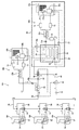
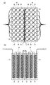
本発明に係る冷却システムの夜間運転時の概略構成図である。The present invention is a schematic diagram of a nighttime operation of the engaging Ru cooling system. 本発明に係る冷却システムの昼間運転時の概略構成図である。A daytime schematic diagram during operation of the engagement Ru cooling system according to the present invention. 本発明に係る冷却システムの霜取り運転時の概略構成図である。The present invention is a schematic diagram of a defrosting during operation of the engaging Ru cooling system. 本発明に係る冷却システムの蓄熱装置の貯留ブライン熱交換部の例を示す図である。It is a figure which shows the example of the storage brine heat exchange part of the thermal storage apparatus of the cooling system which concerns on this invention. 本発明に係る冷却システムの蓄熱装置の貯留ブライン熱交換部の他の例を示す図である。It is a figure which shows the other example of the storage brine heat exchange part of the heat storage apparatus of the cooling system which concerns on this invention.

本発明に係る冷却システム100について図面に基づいて説明する。ここで、図1は本発明に係る冷却システム100の夜間運転時の概略構成図である。また、図2は昼間運転時の概略構成図である。また、図3は霜取り運転時の概略構成図である。尚、図1〜図3中の実線の矢印はCO冷媒及びブラインの流下方向を示すものであり、破線の矢印は制御信号の経路を簡略化して示したものである。 For engagement Ru cooling system 100 of the present invention will be described with reference to the drawings. Here, FIG. 1 is a schematic configuration diagram of a nighttime operation of the engaging Ru cooling system 100 of the present invention. FIG. 2 is a schematic configuration diagram during daytime operation. FIG. 3 is a schematic configuration diagram during the defrosting operation. In addition, the solid line arrow in FIGS. 1 to 3 shows the flow direction of the CO 2 refrigerant and brine, and the broken line arrow shows a simplified control signal path.

先ず、本発明に用いるブラインは、エチレングリコールやプロピレングリコール等の周知の不凍液を水で希釈したものであり、所定の温度(例えば−6℃)で水成分の凍結が開始する濃度に調製する。そして本発明に係る冷却システム100の蓄熱装置80は、このブラインを貯留する蓄熱槽30と、この蓄熱槽30内のブラインを冷却する貯留ブライン冷却手段32Aと、蓄熱槽30内のブラインを冷却負荷50A〜50C側に供給する供給配管40と、を備えている。また、貯留ブライン冷却手段32Aは、CO冷媒を圧縮する圧縮部20aと、この圧縮部20aで圧縮されたCO冷媒を冷却して液化する熱交換部21aと、この熱交換部21aで液化したCO冷媒を断熱膨張させる膨張弁等の周知の膨張部24aと、この膨張部24aにより膨張したCO冷媒との熱交換により蓄熱槽30内のブライン(貯留ブライン)を冷却する貯留ブライン熱交換部26と、を有している。また、貯留ブライン冷却手段32Aは、熱交換部21aで液化したCO冷媒と、貯留ブラインの冷却で使用したCO冷媒との間で熱交換を行う液ガス熱交換部22aを有することが好ましい。尚、圧縮部20a及び熱交換部21aは、CO冷媒を用いた周知の冷凍装置の室外機34aを用いることが好ましい。 First, the brine used in the present invention is prepared by diluting a known antifreeze such as ethylene glycol or propylene glycol with water, and is prepared to a concentration at which freezing of the water component starts at a predetermined temperature (for example, −6 ° C.). The heat storage device 80 of the cooling system 100 according to the present invention includes a heat storage tank 30 for storing the brine, a stored brine cooling means 32A for cooling the brine in the heat storage tank 30, and a brine for cooling the brine in the heat storage tank 30. And a supply pipe 40 to be supplied to the 50A to 50C side. Further, the reservoir brine cooling means 32A includes a compression section 20a for compressing the CO 2 refrigerant, a heat exchange portion 21a for liquefying CO 2 refrigerant compressed in the compression portion 20a is cooled, liquefied in the heat exchange section 21a and known expansion portion 24a, such as an expansion valve for adiabatically expanding the CO 2 refrigerant that has, stored brine heat to cool the brine (reservoir brine) in the heat storage tank 30 by heat exchange with the expanded CO 2 refrigerant by the expansion portion 24a And an exchange unit 26. Further, the reservoir brine cooling means 32A preferably has a CO 2 refrigerant that has liquefied in the heat exchange portion 21a, the liquid-gas heat exchanger section 22a which performs heat exchange between the CO 2 refrigerant used in the cooling of the reservoir brine . The compression portion 20a and the heat exchanger 21a, it is preferable to use the outdoor unit 34a of the known refrigerating apparatus using CO 2 refrigerant.

また、貯留ブライン冷却手段32Aは、CO冷媒中に混入した水分を除去するための周知のドライヤ10を熱交換部21aと液ガス熱交換部22aとの間に有していても良い。また、CO冷媒中に混入した夾雑物を除去する周知のサクションフィルタ12を液ガス熱交換部22aと圧縮部20aとの間に有していても良い。また、貯留ブライン熱交換部26と液ガス熱交換部22aとの間に周知のアキュムレータ14を設けても良い。 The stored brine cooling means 32A may have a known dryer 10 for removing moisture mixed in the CO 2 refrigerant between the heat exchange unit 21a and the liquid gas heat exchange unit 22a. It may also have a known suction filter 12 for removing contaminants mixed in CO 2 refrigerant between the liquid-gas heat exchanger section 22a and the compression portion 20a. Moreover, you may provide the well-known accumulator 14 between the storage brine heat exchange part 26 and the liquid gas heat exchange part 22a.

また、貯留ブライン熱交換部26は蓄熱槽30内に設置され貯留したブラインを所定の設定温度まで冷却するものであり、図4に示すようにコイル形状の冷却配管25を蓄熱槽30内に複数配列したものを用いても良いし、その他の形状のものを用いても良い。中でも図5に示すように、所定の間隔で折り返された折返し管路23を並列に接続し、蓄熱槽30の内部を満たすように構成することが特に好ましい。尚、図4(a)はコイル形状の冷却配管25を用いた貯留ブライン熱交換部26の上面図であり、図4(b)は正面図である。また、図5(a)は折返し管路23を用いた貯留ブライン熱交換部26の正面図であり、図5(b)は側面図である。そして、蓄熱槽30には貯留ブラインの温度を取得する温度センサS2と、貯留ブラインの水位を取得する水位取得手段S1とが設けられている。尚、水位取得手段S1は貯留ブラインの水位を直接取得するものを用いても良いが、圧力センサを用い貯留ブラインの圧力から水位を算出して取得しても良い。   The storage brine heat exchanging unit 26 is installed in the heat storage tank 30 to cool the stored brine to a predetermined set temperature, and a plurality of coil-shaped cooling pipes 25 are provided in the heat storage tank 30 as shown in FIG. Arranged ones or other shapes may be used. In particular, as shown in FIG. 5, it is particularly preferable that the folded pipelines 23 folded at a predetermined interval are connected in parallel to fill the inside of the heat storage tank 30. 4A is a top view of the stored brine heat exchange section 26 using the coil-shaped cooling pipe 25, and FIG. 4B is a front view. FIG. 5A is a front view of the stored brine heat exchanging portion 26 using the folded pipe 23, and FIG. 5B is a side view. The heat storage tank 30 is provided with a temperature sensor S2 for acquiring the temperature of the stored brine and a water level acquiring means S1 for acquiring the water level of the stored brine. In addition, although the water level acquisition means S1 may use what acquires the water level of a storage brine directly, you may calculate and acquire a water level from the pressure of a storage brine using a pressure sensor.

尚、蓄熱槽30の貯留ブラインが冷却され凍結温度に達すると、ブライン中の水成分が凍結し、この際の潜熱も蓄熱がされる。また、このとき貯留ブライン冷却手段32A及び後述のエア攪拌手段36の設定を最適化することで、ブライン中の水成分を微細な氷として凍結させ、貯留ブラインを微細な氷と液体の不凍液とが混在したシャーベット状のアイススラリとしても良い。この構成では供給配管40、ポンプ手段42等をアイススラリの圧送に対応可能なものとすることで、貯留ブラインのアイススラリで冷却負荷50A〜50Cを冷却することができる。この場合、貯留ブラインの顕熱に加え、アイススラリが融解するときの潜熱を直接冷却負荷50A〜50Cの冷却に使用できるため、より高い冷却効率を得ることができる。   When the storage brine in the heat storage tank 30 is cooled and reaches the freezing temperature, the water component in the brine is frozen, and the latent heat at this time is also stored. At this time, by optimizing the settings of the storage brine cooling means 32A and the air stirring means 36 described later, the water component in the brine is frozen as fine ice, and the storage brine is made up of fine ice and liquid antifreeze. A mixed sherbet-like ice slurry may be used. In this configuration, the supply pipe 40, the pump means 42, and the like can cope with ice slurry pressure feeding, so that the cooling loads 50A to 50C can be cooled by the ice slurry of the stored brine. In this case, in addition to the sensible heat of the stored brine, the latent heat when the ice slurry is melted can be used directly for cooling the cooling loads 50A to 50C, so that higher cooling efficiency can be obtained.

さらに、蓄熱装置80はエア攪拌手段36を有することが好ましい。このエア攪拌手段36は蓄熱槽30内の底面側に設けられ、エアポンプ36aにより送気されるエアを底側から気泡として排出することで貯留ブラインを攪拌する。この構成によれば、貯留ブラインを全体的に冷却することが可能となり、無駄の少ない効率的な蓄熱を行うことができる。また、負荷冷却を行う際にも、蓄熱した冷熱を無駄なく使用することが可能となる。特に貯留ブラインに氷が存在している場合には、その氷の潜熱を速やかに貯留ブライン全体に伝導させ負荷の冷却に効果的に用いることができる。   Furthermore, it is preferable that the heat storage device 80 has the air stirring means 36. The air agitating means 36 is provided on the bottom surface side in the heat storage tank 30 and agitates the stored brine by discharging the air supplied from the air pump 36a as bubbles from the bottom side. According to this configuration, the stored brine can be cooled as a whole, and efficient heat storage with little waste can be performed. Further, when performing load cooling, the stored cold energy can be used without waste. In particular, when ice is present in the storage brine, the latent heat of the ice can be quickly conducted to the entire storage brine and used effectively for cooling the load.

また、本発明に係る冷却システム100は、上記の蓄熱装置80と、この蓄熱装置80の供給配管40に接続した冷却負荷50A〜50Cと、蓄熱槽30内の貯留ブラインを供給配管40を介して冷却負荷50A〜50C側に圧送するポンプ手段42と、冷却負荷50A〜50Cで熱交換したブラインを冷却する流下ブライン冷却手段32Bと、吐出側が蓄熱槽30側と供給配管40側とに分岐した3方弁44と、これらの各部を制御する図示しない制御部と、を有している。   Further, the cooling system 100 according to the present invention includes the heat storage device 80, the cooling loads 50 </ b> A to 50 </ b> C connected to the supply pipe 40 of the heat storage device 80, and the stored brine in the heat storage tank 30 via the supply pipe 40. Pump means 42 for pumping to the cooling loads 50A to 50C side, falling brine cooling means 32B for cooling the brine exchanged by the cooling loads 50A to 50C, and the discharge side branch to the heat storage tank 30 side and the supply piping 40 side 3 It has the direction valve 44 and the control part which is not shown in figure which controls these each part.

また、流下ブライン冷却手段32Bは、貯留ブライン冷却手段32Aと同様に、CO冷媒を圧縮する圧縮部20b(第2の圧縮部)と、この圧縮部20bで圧縮されたCO冷媒を冷却して液化する熱交換部21b(第2の熱交換部)と、この熱交換部21bで冷却されたCO冷媒を断熱膨張させる膨張弁等の周知の膨張部24b(第2の膨張部)と、この膨張部24bで膨張したCO冷媒との熱交換により冷却負荷50A〜50Cで熱交換したブラインを冷却するブライン熱交換部28と、を有している。そして、このブライン熱交換部28の下流側に3方弁44が位置する。また、流下ブライン冷却手段32Bは、熱交換部21bで液化したCO冷媒と、ブライン熱交換部28での熱交換したCO冷媒との間で熱交換を行う液ガス熱交換部22bを有することが好ましい。また、圧縮部20b及び熱交換部21bは、貯留ブライン冷却手段32Aと同様に、CO冷媒を用いた周知の冷凍装置の室外機34bを用いることが好ましい。さらに、貯留ブライン冷却手段32Aと同様に、ドライヤ10、サクションフィルタ12等を冷媒経路上に設けることが好ましい。 Also, falling brine cooling means 32B, similarly to the reservoir brine cooling means 32A, CO 2 refrigerant compressing section 20b for compressing (second compression unit), cooling the CO 2 refrigerant compressed in the compression section 20b A heat exchanging part 21b (second heat exchanging part) that is liquefied and a well-known expansion part 24b (second expansion part) such as an expansion valve that adiabatically expands the CO 2 refrigerant cooled by the heat exchanging part 21b; And a brine heat exchanging section 28 for cooling the brine exchanged with the cooling loads 50A to 50C by heat exchange with the CO 2 refrigerant expanded in the expansion section 24b. A three-way valve 44 is located downstream of the brine heat exchange unit 28. Also, falling brine cooling unit 32B includes a CO 2 refrigerant that has liquefied in the heat exchanger 21b, the liquid-gas heat exchanger section 22b that performs heat exchange between the CO 2 refrigerant heat exchange in the brine heat exchanger unit 28 It is preferable. The compression unit 20b and the heat exchanger section 21b, similarly to the reservoir brine cooling means 32A, it is preferable to use the outdoor unit 34b of the known refrigerating apparatus using CO 2 refrigerant. Further, like the stored brine cooling means 32A, it is preferable to provide the dryer 10, the suction filter 12, etc. on the refrigerant path.

また、冷却負荷50A〜50Cは、例えば冷蔵ショーケース、冷蔵倉庫、その他の冷蔵設備、冷房空調設備等であり、供給配管40からのブラインと庫内(室内)の空気とを熱交換して冷却する熱交換器52をそれぞれ有している。また、各熱交換器52の上流には3方弁54がそれぞれ設けられており、この3方弁54の一方の吐出側がそれぞれの熱交換器52と接続する。また、3方弁54の他方の吐出側には熱交換器52の下流で合流するバイパス管56が接続する。また、各冷却負荷50A〜50Cには庫内の温度を測定して出力する温度センサS4がそれぞれ設けられている。   The cooling loads 50A to 50C are, for example, refrigerated showcases, refrigerated warehouses, other refrigeration facilities, air conditioning units, etc., and cool by cooling heat between the brine from the supply pipe 40 and the air in the room (indoor). Each has a heat exchanger 52 to be operated. A three-way valve 54 is provided upstream of each heat exchanger 52, and one discharge side of the three-way valve 54 is connected to each heat exchanger 52. A bypass pipe 56 that joins downstream of the heat exchanger 52 is connected to the other discharge side of the three-way valve 54. Further, each of the cooling loads 50A to 50C is provided with a temperature sensor S4 that measures and outputs the temperature in the cabinet.

尚、冷却負荷50A〜50Cは単体で構成しても良いが、基本的に複数台接続して用いる。この際、冷却負荷50A〜50Cは直列に接続し、さらに低温での冷蔵が要求される例えば、肉、魚貝類用の冷蔵ショーケースを上流側(冷却負荷50A)に配置し、それよりも若干高い温度での冷蔵が許容される例えば、野菜や飲料用の冷蔵ショーケースや冷房空調設備等(冷却負荷50B、50C)を下流側に順に配置する。この構成では上流側の冷却負荷50Aに低温のブライン(もしくはアイススラリ)が供給され、このブラインとの熱交換により庫内の冷却が行われる。また、この冷却に用いられたブラインは下流側の冷却負荷50B、50Cに順々に供給され、それぞれの熱交換器52において熱交換が行われ庫内(室内)の冷却が行われる。この構成では、低い冷却温度が要求される冷却負荷50Aに最も低温のブラインを供給して庫内の冷却を行い、さほどの冷却温度が要求されない冷却負荷50B、50Cには前段の冷却負荷で使用したブラインを用いて冷却を行う。このように、ブラインの持つ冷熱をカスケード的に無駄なく利用することで、冷却負荷50A〜50Cの効率的な冷却を行うことができる。そして、冷却負荷50A〜50Cの冷却に使用されたブラインは帰還配管46を介して3方弁44側に流下する。   The cooling loads 50A to 50C may be configured as a single unit, but basically a plurality of cooling loads are connected and used. At this time, the cooling loads 50A to 50C are connected in series, and for example, a refrigerated showcase for meat and fish and shellfish, which is required to be refrigerated at a low temperature, is arranged on the upstream side (cooling load 50A). For example, a refrigerated showcase for vegetables and beverages, a cooling air-conditioning facility (cooling loads 50B, 50C), etc., which are allowed to be refrigerated at a high temperature, are sequentially arranged on the downstream side. In this configuration, low-temperature brine (or ice slurry) is supplied to the cooling load 50A on the upstream side, and the interior is cooled by heat exchange with this brine. Further, the brine used for this cooling is sequentially supplied to the cooling loads 50B and 50C on the downstream side, and heat exchange is performed in the respective heat exchangers 52 to cool the interior (inside the room). In this configuration, the coldest brine is supplied to the cooling load 50A that requires a low cooling temperature to cool the inside of the cabinet, and the cooling loads 50B and 50C that do not require much cooling temperature are used at the preceding cooling load. Cool with the brine. Thus, efficient cooling of the cooling loads 50A to 50C can be performed by using the cold heat of the brine in a cascade manner without waste. The brine used for cooling the cooling loads 50 </ b> A to 50 </ b> C flows down to the three-way valve 44 side via the return pipe 46.

また、供給配管40には自身を流下するブラインの温度を取得する温度センサS3が設けられ、昼間運転においては温度センサS3が取得したブラインの温度に応じて3方弁44の吐出側の開口比率が制御される。また、流下ブライン熱交換部28の前後には、冷却負荷50A〜50Cによる熱交換後のブラインの温度を取得する温度センサS5と、流下ブライン熱交換部28による熱交換後のブラインの温度を取得する温度センサS6とが設けられ、この温度センサS5が取得したブラインの温度に応じてポンプ手段42の吐出量が制御される。また、温度センサS6が取得したブラインの温度に応じて流下ブライン冷却手段32Bのオン・オフが制御される。   Further, the supply pipe 40 is provided with a temperature sensor S3 for acquiring the temperature of the brine flowing down, and in the daytime operation, the opening ratio on the discharge side of the three-way valve 44 according to the temperature of the brine acquired by the temperature sensor S3. Is controlled. Further, before and after the downstream brine heat exchange section 28, a temperature sensor S5 that acquires the temperature of the brine after heat exchange by the cooling loads 50A to 50C and the temperature of the brine after heat exchange by the downstream brine heat exchange section 28 are acquired. The temperature sensor S6 is provided, and the discharge amount of the pump means 42 is controlled in accordance with the brine temperature acquired by the temperature sensor S5. Further, the on / off of the falling brine cooling means 32B is controlled according to the brine temperature acquired by the temperature sensor S6.

次に、本発明に係る冷却システム100の夜間運転時の動作を図1を用いて説明する。尚、冷却システム100の昼間運転と夜間運転、及び霜取り運転の切替は、例えば制御部に設定されたタイマによって行われる。 Next, the operation during night driving engagement Ru cooling system 100 of the present invention will be described with reference to FIG. The switching between the daytime operation, the nighttime operation, and the defrosting operation of the cooling system 100 is performed by a timer set in the control unit, for example.

先ず、夜間運転において制御部は3方弁44の流路を供給配管40側とする。これにより、冷却負荷50A〜50C側を流下するブラインの流路と、蓄熱槽30とは分離する。そして、制御部は貯留ブライン冷却手段32Aを動作させる。これにより、圧縮部20aが動作してCO冷媒を圧縮し高温高圧状態にして吐出する。次に、この高温高圧のCO冷媒は熱交換部21aにおいて外気もしくは水との熱交換により冷却し液化する。次に、このCO冷媒はドライヤ10により内部に混入した不要な水分が除去された後、液ガス熱交換部22aにて貯留ブラインの冷却に用いられたCO冷媒との間で熱交換が行われ、さらに冷却する。次に、このCO冷媒は膨張部24aにて断熱膨張し低温低圧の気液二相冷媒となる。次に、このCO冷媒は蓄熱槽30内に設けられた貯留ブライン熱交換部26を流下して蓄熱槽30内の貯留ブラインとの間で熱交換が行われ気化する。そして、この際のCO冷媒の吸熱により貯留ブラインの温度が低下する。この貯留ブラインの温度は温度センサS2が取得して制御部に出力する。次に、気化したCO冷媒はアキュムレータ14を介して液ガス熱交換部22aに流入し、上流側のCO冷媒(液相)との間で熱交換がなされる。次に、CO冷媒はサクションフィルタ12にて無用な夾雑物が除去された後、圧縮部20aに吸引され、高温高圧のCO冷媒として再度吐出される。 First, in the night operation, the control unit sets the flow path of the three-way valve 44 to the supply pipe 40 side. Thereby, the flow path of the brine flowing down on the cooling loads 50A to 50C side and the heat storage tank 30 are separated. Then, the control unit operates the stored brine cooling means 32A. As a result, the compression unit 20a operates to compress the CO 2 refrigerant and discharge it in a high temperature and high pressure state. Next, the high-temperature and high-pressure CO 2 refrigerant is cooled and liquefied by heat exchange with the outside air or water in the heat exchange section 21a. Next, after the unnecessary moisture mixed inside the CO 2 refrigerant is removed by the dryer 10, heat exchange is performed between the CO 2 refrigerant and the CO 2 refrigerant used for cooling the stored brine in the liquid gas heat exchange unit 22 a. Done and further cooling. Next, the CO 2 refrigerant is adiabatically expanded in the expansion section 24a and becomes a low-temperature and low-pressure gas-liquid two-phase refrigerant. Then, the CO 2 refrigerant heat exchange is performed by flowing down the reservoir brine heat exchanger unit 26 provided in the heat storage tank 30 with the reservoir brine in the heat storage tank 30 to vaporize. Then, the temperature of the reservoir brine is reduced by the heat absorption of the CO 2 refrigerant at this time. The temperature of the storage brine is acquired by the temperature sensor S2 and output to the control unit. Next, the vaporized CO 2 refrigerant flows into the liquid gas heat exchange section 22a via the accumulator 14, and heat exchange is performed with the upstream CO 2 refrigerant (liquid phase). Next, after unnecessary impurities are removed by the suction filter 12, the CO 2 refrigerant is sucked into the compression unit 20a and discharged again as a high-temperature and high-pressure CO 2 refrigerant.

また、制御部は温度センサS2を介して取得した貯留ブラインの温度が予め設定された特定の温度範囲になった場合、もしくは、予め設定した時間帯となった場合にエアポンプ36aを動作させる。これにより、エア攪拌手段36から気泡が吐出し貯留ブラインを攪拌する。これにより、貯留ブライン熱交換部26による熱交換が万遍なく行われ、貯留ブラインの温度が全体的に低下する。そして、貯留ブラインの温度が凍結温度に達すると貯留ブライン中の水分が凍結する。この凍結により貯留ブラインの体積は増大し水位が上昇する。この貯留ブラインの水位の変化は水位取得手段S1が取得して制御部に出力する。そして、制御部は貯留ブラインの水位が予め設定された上限水位に達すると貯留ブライン冷却手段32Aを停止する。これにより、貯留ブラインの過剰な凍結(蓄熱)は防止される。また、制御部は温度センサS2を介して取得した貯留ブラインの温度が予め設定された下限温度に達すると貯留ブライン冷却手段32Aを停止する。これにより、蓄熱槽30には所定の温度のブラインが貯留する。尚、制御部は貯留ブラインが上限水位及び下限温度に達しない場合でも、予め設定された時間帯を超えた場合に貯留ブライン冷却手段32Aを停止する。   In addition, the control unit operates the air pump 36a when the temperature of the storage brine acquired via the temperature sensor S2 falls within a specific temperature range set in advance or when a preset time zone is reached. Thereby, air bubbles are discharged from the air agitating means 36 and the stored brine is agitated. Thereby, the heat exchange by the storage brine heat exchange part 26 is performed uniformly, and the temperature of the storage brine falls entirely. When the temperature of the storage brine reaches the freezing temperature, the water in the storage brine is frozen. This freezing increases the volume of the stored brine and raises the water level. The change in the water level of the stored brine is acquired by the water level acquisition means S1 and output to the control unit. Then, the control unit stops the stored brine cooling means 32A when the water level of the stored brine reaches the preset upper limit water level. Thereby, excessive freezing (heat storage) of the storage brine is prevented. Further, the control unit stops the stored brine cooling means 32A when the temperature of the stored brine acquired via the temperature sensor S2 reaches a preset lower limit temperature. Thereby, brine of a predetermined temperature is stored in the heat storage tank 30. Even if the storage brine does not reach the upper limit water level and the lower limit temperature, the control unit stops the storage brine cooling means 32A when the preset time zone is exceeded.

また、これと並行して、制御部は温度センサS5を介して帰還配管46を流下するブラインの温度を取得して、その温度に応じてポンプ手段42を動作させる。尚、ポンプ手段42は周知のインバータ制御により吐出量の調整が可能であり、制御部はブラインの温度が高い場合にはポンプ手段42の吐出量を増大させ、ブラインの温度が低い場合にはポンプ手段42の吐出量を減少させる。   In parallel with this, the control unit acquires the temperature of the brine flowing down the return pipe 46 via the temperature sensor S5, and operates the pump means 42 in accordance with the temperature. The pump means 42 can adjust the discharge amount by well-known inverter control, and the control unit increases the discharge amount of the pump means 42 when the brine temperature is high, and the pump when the brine temperature is low. The discharge amount of the means 42 is reduced.

また、制御部は温度センサS6を介して流下ブライン熱交換部28の下流側のブラインの温度を取得して、その温度が予め設定された温度を超えた場合に流下ブライン冷却手段32Bを動作させる。これにより、流下ブライン冷却手段32Bの圧縮部20bが動作してCO冷媒を圧縮し高温高圧状態にして吐出する。次に、この高温高圧のCO冷媒は熱交換部21bにおいて外気もしくは水との熱交換により冷却し液化する。次に、このCO冷媒はドライヤ10により内部に混入した不要な水分が除去された後、液ガス熱交換部22bにてブライン熱交換部28の熱交換で使用したCO冷媒との間で熱交換が行われ、さらに冷却する。次に、このCO冷媒は膨張部24bにて断熱膨張し低温低圧の気液二相冷媒となる。次に、このCO冷媒は流下ブライン熱交換部28を流下して帰還配管46を流下するブラインとの間で熱交換が行われ気化する。そして、この際のCO冷媒の吸熱によりブラインの温度が低下する。この熱交換後のブラインの温度は温度センサS6が取得して制御部に出力する。次に、気化したCO冷媒は液ガス熱交換部22bに流入し、上流側のCO冷媒(液相)との間で熱交換がなされる。次に、CO冷媒はサクションフィルタ12にて無用な夾雑物が除去された後、圧縮部20bに吸引され、高温高圧のCO冷媒として再度吐出される。 Further, the control unit acquires the temperature of the brine on the downstream side of the flowing-down brine heat exchanging unit 28 via the temperature sensor S6, and operates the flowing-down brine cooling means 32B when the temperature exceeds a preset temperature. . As a result, the compression unit 20b of the falling brine cooling means 32B operates to compress the CO 2 refrigerant and discharge it in a high temperature and high pressure state. Next, this high-temperature and high-pressure CO 2 refrigerant is cooled and liquefied by heat exchange with the outside air or water in the heat exchange section 21b. Next, after the unnecessary moisture mixed inside is removed by the dryer 10, the CO 2 refrigerant is exchanged with the CO 2 refrigerant used in the heat exchange of the brine heat exchange section 28 in the liquid gas heat exchange section 22b. Heat exchange takes place and further cooling. Next, the CO 2 refrigerant is adiabatically expanded in the expansion section 24b and becomes a low-temperature and low-pressure gas-liquid two-phase refrigerant. Next, the CO 2 refrigerant is vaporized by performing heat exchange with the brine flowing down through the falling brine heat exchanging section 28 and flowing down through the return pipe 46. Then, the temperature of the brine by the heat absorption of the CO 2 refrigerant at this time is reduced. The temperature of the brine after the heat exchange is acquired by the temperature sensor S6 and output to the control unit. Next, the vaporized CO 2 refrigerant flows into the liquid gas heat exchange unit 22b, and heat exchange is performed with the upstream CO 2 refrigerant (liquid phase). Next, after unnecessary impurities are removed by the suction filter 12, the CO 2 refrigerant is sucked into the compression unit 20b and discharged again as a high-temperature and high-pressure CO 2 refrigerant.

また、流下ブライン熱交換部28で冷却されたブラインは3方弁44を通して供給配管40に流入し、ポンプ手段42によって冷却負荷50A〜50C側に圧送される。尚、供給配管40を流下するブラインの温度は温度センサS3が取得するが、夜間運転においては温度センサS3に基づく特別な制御は行われない。   Further, the brine cooled by the falling brine heat exchange section 28 flows into the supply pipe 40 through the three-way valve 44 and is pumped to the cooling loads 50A to 50C by the pump means 42. Although the temperature sensor S3 acquires the temperature of the brine flowing down the supply pipe 40, special control based on the temperature sensor S3 is not performed during nighttime operation.

そして、ポンプ手段42で圧送されたブラインは最上流に位置する冷却負荷50Aの3方弁54に到達する。このとき制御部は、冷却負荷50Aの温度センサS4を介して取得した庫内の温度が予め設定された温度よりも高い場合に、3方弁54の吐出方向を熱交換器52側とする。この場合、ブラインは熱交換器52を流下して庫内の空気との熱交換が行われ、冷却負荷50Aの庫内の温度を低下させる。そして、後段の冷却負荷50B側に流下する。また、冷却負荷50Aの庫内の温度が予め設定された温度よりも低い場合、制御部は冷却負荷50Aの冷却状態は十分であるとして3方弁54の吐出方向をバイパス管56側とする。この場合、ブラインは熱交換器52を通らずにバイパス管56を通って後段の冷却負荷50B側に直接流下する。そして、冷却負荷50B側に流下したブラインは、冷却負荷50Aと全く同様にして熱交換器52もしくはバイパス管56を通って冷却負荷50C側に流下する。また、冷却負荷50C側に流下したブラインは、同様にして熱交換器52もしくはバイパス管56を通って帰還配管46に流下する。そして、流下ブライン熱交換部28にて冷却された後、供給配管40を介して再度冷却負荷50A〜50Cの冷却に給される。また、制御部は温度センサS6を介して取得したブラインの温度が予め設定された温度以下となった場合に流下ブライン冷却手段32Bを停止する。これにより、過度の冷却による流下ブライン熱交換部28内でのブラインの凍結を防止することができる。   Then, the brine pumped by the pump means 42 reaches the three-way valve 54 of the cooling load 50A located at the uppermost stream. At this time, the control unit sets the discharge direction of the three-way valve 54 to the heat exchanger 52 side when the internal temperature acquired via the temperature sensor S4 of the cooling load 50A is higher than a preset temperature. In this case, the brine flows down the heat exchanger 52 to exchange heat with the air in the warehouse, and lowers the temperature in the warehouse of the cooling load 50A. And it flows down to the cooling load 50B side of a back | latter stage. Further, when the temperature in the chamber of the cooling load 50A is lower than a preset temperature, the control unit assumes that the cooling state of the cooling load 50A is sufficient and sets the discharge direction of the three-way valve 54 to the bypass pipe 56 side. In this case, the brine flows down directly to the cooling load 50B side through the bypass pipe 56 without passing through the heat exchanger 52. Then, the brine flowing down to the cooling load 50B side flows down to the cooling load 50C side through the heat exchanger 52 or the bypass pipe 56 in exactly the same manner as the cooling load 50A. Similarly, the brine that has flowed down to the cooling load 50 </ b> C flows down to the return pipe 46 through the heat exchanger 52 or the bypass pipe 56. And after cooling in the falling brine heat exchange part 28, it is supplied to cooling of cooling load 50A-50C again through the supply piping 40. FIG. Further, the control unit stops the flowing-down brine cooling means 32B when the temperature of the brine acquired via the temperature sensor S6 becomes equal to or lower than a preset temperature. Thereby, freezing of the brine in the flowing-down brine heat exchange part 28 by excessive cooling can be prevented.

ここで、夜間では冷却負荷50A〜50Cの負荷量が日中と比較して小さい。そして、流下ブライン冷却手段32Bの各部は、夜間における冷却負荷50A〜50Cの負荷量を補える能力に設計される。   Here, at night, the loads of the cooling loads 50A to 50C are smaller than those during the day. And each part of the flowing-down brine cooling means 32B is designed by the capability which can supplement the load amount of the cooling loads 50A-50C at night.

次に、本発明に係る冷却システム100の昼間運転時の動作を図2を用いて説明する。先ず、昼間運転においては貯留ブライン冷却手段32Aは基本的に停止する。ただし、温度センサS2が取得する貯留ブラインの温度が予め設定されている上限温度を超えた場合には、制御部が貯留ブライン冷却手段32Aを動作させ、夜間運転時と同様に貯留ブラインの冷却を行う。 Next, the operation of the daytime during operation of the engaging Ru cooling system 100 of the present invention will be described with reference to FIG. First, in the daytime operation, the stored brine cooling means 32A basically stops. However, when the temperature of the stored brine acquired by the temperature sensor S2 exceeds the preset upper limit temperature, the control unit operates the stored brine cooling means 32A to cool the stored brine in the same way as during night operation. Do.

また、制御部は流下ブライン冷却手段32B及び各3方弁54を夜間運転時と同様に制御する。また、制御部は温度センサS3が取得する供給配管40のブラインの温度に応じて3方弁44の供給配管40側と蓄熱槽30側の開度を調整する。即ち、温度センサS3の温度が設定温度と同等もしくは低い場合、制御部は3方弁44の供給配管40側の開口比率を大きく、蓄熱槽30側の開口比率が小さくなるように制御する。これにより、ブラインの供給配管40への還流量が多くなり、蓄熱槽30への還流量が少なくなる。この場合、冷却負荷50A〜50Cの冷却は流下ブライン冷却手段32B側が主体的に行う。   Further, the control unit controls the falling brine cooling means 32B and each three-way valve 54 in the same manner as during night operation. Moreover, a control part adjusts the opening degree of the supply piping 40 side of the three-way valve 44, and the thermal storage tank 30 side according to the temperature of the brine of the supply piping 40 which temperature sensor S3 acquires. That is, when the temperature of the temperature sensor S3 is equal to or lower than the set temperature, the control unit controls the opening ratio of the three-way valve 44 on the supply pipe 40 side to be large and the opening ratio on the heat storage tank 30 side to be small. Thereby, the recirculation | reflux amount to the supply piping 40 of brine increases, and the recirculation | reflux amount to the thermal storage tank 30 decreases. In this case, cooling of the cooling loads 50A to 50C is mainly performed by the falling brine cooling means 32B side.

また、温度センサS3の温度が設定温度よりも高い場合、即ち冷却負荷50A〜50Cの負荷量が増大し流下ブライン冷却手段32Bの能力を超えた場合、制御部は3方弁44の蓄熱槽30側の開口比率を大きく、供給配管40側の開口比率が小さくなるように制御する。この場合、ブラインの蓄熱槽30への還流量が増大するとともに、供給配管40への還流量が減少する。これにより、蓄熱槽30から低温の貯留ブラインが供給配管40に流入し、冷却負荷50A〜50Cの冷却に給される。また、蓄熱槽30内に吐出されたブラインは貯留ブラインによって冷却される。これにより、流下ブライン冷却手段32Bの負荷は軽減され、日中の電力消費を抑制することが可能となる。   In addition, when the temperature of the temperature sensor S3 is higher than the set temperature, that is, when the load amount of the cooling loads 50A to 50C increases and exceeds the capacity of the falling brine cooling means 32B, the control unit performs the heat storage tank 30 of the three-way valve 44. The opening ratio on the side is increased and the opening ratio on the supply pipe 40 side is controlled to be smaller. In this case, the recirculation amount of the brine to the heat storage tank 30 increases, and the recirculation amount to the supply pipe 40 decreases. Thereby, the low-temperature storage brine flows from the heat storage tank 30 into the supply pipe 40 and is supplied to the cooling of the cooling loads 50A to 50C. Moreover, the brine discharged into the heat storage tank 30 is cooled by the stored brine. As a result, the load on the falling brine cooling means 32B is reduced, and the power consumption during the day can be suppressed.

次に、本発明に係る冷却システム100の霜取り運転時の動作を図3を用いて説明する。尚、霜取り運転は冷却負荷50A〜50Cの熱交換器52に付着した霜を融解して除去するためのものであり、夜間運転、昼間運転を問わず予め設定された間隔で定期的に行われる。 Next, the operation during defrosting operation of the engaging Ru cooling system 100 of the present invention will be described with reference to FIG. The defrosting operation is for melting and removing frost adhering to the heat exchangers 52 of the cooling loads 50A to 50C, and is periodically performed at predetermined intervals regardless of whether the operation is nighttime operation or daytime operation. .

冷却システム100における霜取り運転では、制御部は3方弁44の吐出方向を供給配管40側にする。これにより、冷却負荷50A〜50C側を流下するブラインの流路と、蓄熱槽30とは分離する。また、制御部は冷却負荷50A〜50Cの3方弁54の吐出方向を全て熱交換器52側とする。そして、制御部は流下ブライン冷却手段32Bを停止する。これにより、冷却負荷50A〜50Cで熱交換されたブラインは冷却されることなく全ての熱交換器52内を循環する。そして、これを一定時間継続して行うことで熱交換器52に付着した霜は融解し除去される。そして、規定の時間の霜取り運転が終了すると、流下ブライン冷却手段32Bは前述の夜間運転もしくは昼間運転動作に復帰する。尚、貯留ブライン冷却手段32Aは霜取り運転時でも特別な動作は行わず、夜間運転時、昼間運転時の動作をそのまま維持する。   In the defrosting operation in the cooling system 100, the control unit sets the discharge direction of the three-way valve 44 to the supply pipe 40 side. Thereby, the flow path of the brine flowing down on the cooling loads 50A to 50C side and the heat storage tank 30 are separated. Further, the control unit sets all the discharge directions of the three-way valves 54 of the cooling loads 50A to 50C to the heat exchanger 52 side. Then, the control unit stops the falling brine cooling means 32B. Thereby, the brine subjected to heat exchange with the cooling loads 50 </ b> A to 50 </ b> C circulates in all the heat exchangers 52 without being cooled. And by performing this for a certain period of time, the frost adhering to the heat exchanger 52 is melted and removed. When the defrosting operation for a specified time is completed, the falling brine cooling means 32B returns to the night operation or daytime operation described above. The stored brine cooling means 32A does not perform any special operation even during the defrosting operation, and maintains the operation during the night operation and the daytime operation as it is.

以上のように、本発明に係る冷却システム100は温暖化係数の小さいCO冷媒を用いてブラインの冷却を行い、このブラインを用いて冷却負荷50A〜50Cの冷却を行う。これにより、温暖化係数の高い温室効果ガスの使用量を低減することができる。 As described above, cooling system 100 Ru engaged to the present invention performs a brine cooled with a smaller CO 2 refrigerant global warming potential, to cool the cooling load 50A~50C with this brine. Thereby, the usage-amount of greenhouse gas with a high global warming potential can be reduced.

また、本発明に係る冷却システム100は、比較的電力料金が割安で且つ昼間よりも外気温度が低い夜間に貯留ブラインを高効率で冷却し蓄熱を行う。そして、昼間運転ではこの貯留ブラインの冷熱を冷却負荷50A〜50Cの冷却に用いる。これにより、昼間運転における流下ブライン冷却手段32Bの負荷が軽減され、日中の電力消費を抑制することができる。これにより、エネルギーコストの削減を図ることが可能な他、夜間の余剰な電力の有効活用が可能となり、省エネルギー化に貢献することができる。   In addition, the cooling system 100 according to the present invention cools the stored brine with high efficiency and stores heat at night when the power rate is relatively cheap and the outside air temperature is lower than the daytime. In the daytime operation, the cold energy of the stored brine is used for cooling the cooling loads 50A to 50C. Thereby, the load of the falling brine cooling means 32B in the daytime operation is reduced, and the power consumption during the day can be suppressed. As a result, energy costs can be reduced, and surplus power at night can be effectively used, contributing to energy savings.

さらに、本発明に係る冷却システム100は、流下ブライン冷却手段32Bを停止して、ブラインの循環により熱交換器52の霜取りを行う。これにより、さらなるエネルギーコストの削減と省エネルギー化を図ることができる。   Furthermore, the cooling system 100 according to the present invention stops the falling brine cooling means 32B and defrosts the heat exchanger 52 by circulating the brine. As a result, further energy cost reduction and energy saving can be achieved.

尚、本例で示した蓄熱装置80、蓄熱槽30、冷却システム100の各部の構成、機構、形状、寸法、配管経路、動作等は一例であるから、本例に限定される訳ではなく、本発明は本発明の要旨を逸脱しない範囲で変更して実施することが可能である。   In addition, since the structure, mechanism, shape, dimension, piping route, operation, etc. of each part of the heat storage device 80, the heat storage tank 30, and the cooling system 100 shown in this example are examples, they are not limited to this example. The present invention can be modified and implemented without departing from the scope of the present invention.

20a 圧縮部
20b (第2の)圧縮部
21a 熱交換部
21b (第2の)熱交換部
24a 膨張部
24b (第2の)膨張部
26 貯留ブライン熱交換部
28 流下ブライン熱交換部
30 蓄熱槽
32A 貯留ブライン冷却手段
32B 流下ブライン冷却手段
36 エア攪拌手段
40 供給配管
42 ポンプ手段
44 3方弁
50A〜50C 冷却負荷
80 蓄熱装置
100 冷却システム
20a Compression unit
20b (second) compression unit
21a Heat exchange section
21b (second) heat exchange section
24a Expansion part
24b (second) expansion part
26 Storage brine heat exchanger
28 Downstream brine heat exchanger
30 heat storage tank
32A storage brine cooling means
32B Flowing brine cooling means
36 Air stirring means
40 Supply piping
42 Pump means
44 3-way valve
50A-50C Cooling load
80 heat storage device
100 cooling system

Claims (4)

不凍液を水で所定の濃度に希釈したブラインを貯留する蓄熱槽と、前記蓄熱槽内のブラインを冷却する貯留ブライン冷却手段と、前記蓄熱槽内のブラインを冷却負荷側に供給する供給配管と、を備え、前記貯留ブライン冷却手段は、CO冷媒を圧縮する圧縮部と、前記圧縮部で圧縮されたCO冷媒を熱交換して液化する熱交換部と、前記熱交換部で液化したCO2冷媒を断熱膨張させる膨張部と、前記膨張部で膨張したCO冷媒との熱交換により前記蓄熱槽内のブラインを冷却する貯留ブライン熱交換部と、を有した蓄熱装置と、
前記供給配管に接続した冷却負荷と、
前記蓄熱槽内のブラインを前記供給配管を介して前記冷却負荷側に圧送するポンプ手段と、
前記冷却負荷で熱交換したブラインを冷却する流下ブライン冷却手段と、
前記流下ブライン冷却手段を構成しCO 冷媒を圧縮する第2の圧縮部と、前記流下ブライン冷却手段を構成し前記第2の圧縮部で圧縮されたCO 冷媒を冷却して液化する第2の熱交換部と、前記流下ブライン冷却手段を構成し前記第2の熱交換部で冷却されたCO 冷媒を断熱膨張させる第2の膨張部と、前記流下ブライン冷却手段を構成し前記第2の膨張部で膨張したCO 冷媒との熱交換により前記冷却負荷で熱交換したブラインを冷却する流下ブライン熱交換部と、
前記流下ブライン熱交換部の下流側に位置し吐出側が前記蓄熱槽側と前記供給配管側とに分岐した3方弁と、を有することを特徴とする冷却システム。
A heat storage tank for storing brine in which the antifreeze is diluted to a predetermined concentration with water, storage brine cooling means for cooling the brine in the heat storage tank, supply piping for supplying the brine in the heat storage tank to the cooling load side, The storage brine cooling means includes a compression unit that compresses the CO 2 refrigerant, a heat exchange unit that exchanges heat to liquefy the CO 2 refrigerant compressed by the compression unit, and CO 2 that is liquefied by the heat exchange unit an expansion unit for refrigerant adiabatically expanded, and the heat storage device have a, a reservoir brine heat exchanger unit for cooling the brine of the heat storage tank by the heat exchange with the expanded CO 2 refrigerant by the expansion unit,
A cooling load connected to the supply pipe;
Pump means for pumping the brine in the heat storage tank to the cooling load side via the supply pipe;
A falling brine cooling means for cooling the brine subjected to heat exchange with the cooling load;
A second compression section that configures the downstream brine cooling means and compresses the CO 2 refrigerant; and a second compression section that configures the downstream brine cooling means and cools and liquefies the CO 2 refrigerant compressed by the second compression section . A second expansion part that constitutes the falling brine cooling means and adiabatic expansion of the CO 2 refrigerant cooled by the second heat exchange part, and constitutes the falling brine cooling means. A falling brine heat exchange section for cooling the brine heat-exchanged with the cooling load by heat exchange with the CO 2 refrigerant expanded in the expansion section ;
A cooling system comprising a three-way valve located downstream of the downflow brine heat exchange section and having a discharge side branched into the heat storage tank side and the supply piping side.
蓄熱槽内に気泡を吐出してブラインを攪拌するエア攪拌手段をさらに有することを特徴とする請求項1記載の冷却システムThe cooling system according to claim 1, further comprising an air agitating means for agitating the brine by discharging bubbles into the heat storage tank. 夜間運転時には、3方弁の流路を供給配管側にするとともに、貯留ブライン冷却手段と流下ブライン冷却手段とが冷却動作を行い、前記貯留ブライン冷却手段が蓄熱槽内のブラインを冷却するとともに、前記流下ブライン冷却手段が供給配管内を流下するブラインを冷却し、
昼間運転時には、供給配管内を流下するブラインの温度に応じて3方弁が前記蓄熱槽側へのブラインの還流量と供給配管側へのブラインの還流量を変化させることを特徴とする請求項1または請求項2に記載の冷却システム。
During night operation, the flow path of the three-way valve is on the supply pipe side, the storage brine cooling means and the falling brine cooling means perform a cooling operation, and the storage brine cooling means cools the brine in the heat storage tank, The falling brine cooling means cools the brine flowing down in the supply pipe;
The daytime during operation, claims, characterized in that changing the recirculation amount of the brine to the reflux amount and the supply pipe side of the brine to the 3-way valve the heat storage tank side according to the temperature of the brine flowing down the supply pipe The cooling system according to claim 1 or 2 .
冷却負荷の熱交換器に対する霜取り運転時には、流下ブライン冷却手段を停止するとともに、3方弁の流路を供給配管側とすることを特徴とする請求項1乃至請求項3のいずれかに記載の冷却システム。 During defrosting operation for the heat exchanger of the cooling load, stops the falling brine cooling means, according to 3-way valve flow paths to one of claims 1 to 3, characterized in that the feed pipe side Cooling system.
JP2018149003A 2018-08-08 2018-08-08 Cooling system Active JP6582102B1 (en)

Priority Applications (1)

Application Number Priority Date Filing Date Title
JP2018149003A JP6582102B1 (en) 2018-08-08 2018-08-08 Cooling system

Applications Claiming Priority (1)

Application Number Priority Date Filing Date Title
JP2018149003A JP6582102B1 (en) 2018-08-08 2018-08-08 Cooling system

Publications (2)

Publication Number Publication Date
JP6582102B1 true JP6582102B1 (en) 2019-09-25
JP2020024069A JP2020024069A (en) 2020-02-13

Family

ID=68053624

Family Applications (1)

Application Number Title Priority Date Filing Date
JP2018149003A Active JP6582102B1 (en) 2018-08-08 2018-08-08 Cooling system

Country Status (1)

Country Link
JP (1) JP6582102B1 (en)

Cited By (1)

* Cited by examiner, † Cited by third party
Publication number Priority date Publication date Assignee Title
US12325617B2 (en) 2020-10-14 2025-06-10 Samsung Electronics Co., Ltd. Water purifier and method for controlling same

Family Cites Families (3)

* Cited by examiner, † Cited by third party
Publication number Priority date Publication date Assignee Title
JP3596347B2 (en) * 1998-04-15 2004-12-02 三菱電機株式会社 Refrigeration air conditioner and control method thereof
JP2000074542A (en) * 1998-08-25 2000-03-14 Sanyo Electric Co Ltd Cooling system for showcase
JP6405521B2 (en) * 2014-03-04 2018-10-17 パナソニックIpマネジメント株式会社 Heat pump hot water generator

Cited By (1)

* Cited by examiner, † Cited by third party
Publication number Priority date Publication date Assignee Title
US12325617B2 (en) 2020-10-14 2025-06-10 Samsung Electronics Co., Ltd. Water purifier and method for controlling same

Also Published As

Publication number Publication date
JP2020024069A (en) 2020-02-13

Similar Documents

Publication Publication Date Title
EP2545332B1 (en) Refrigerant distribution apparatus and methods for transport refrigeration system
CA2662986C (en) Co2 refrigeration unit
US20090293507A1 (en) Thermal energy storage and cooling system with isolated evaporator coil
JP5854751B2 (en) Cooling system
JPH06300381A (en) Heat storage type air conditioner and defrosting method
EP2703753A1 (en) Refrigeration appliance with two evaporators in different compartments
US11680739B2 (en) Vapour compression apparatus
CN107238225A (en) Cooling system with integrated refrigerating function again
JP6582102B1 (en) Cooling system
CN115839524A (en) Air conditioning system with dynamic ice storage function and control method thereof
KR20100114296A (en) Apparatus for refrigeration cycle using ice thermal storage and showcase including the apparatus and control method for the same
CN114198951A (en) Double-effect integrated refrigeration unit with natural cooling and refrigeration method thereof
JP5693932B2 (en) Cooling system and cooling method
KR20100046705A (en) Ice thermal storage system using closed-circuit
JP4270803B2 (en) Cold generation system
JP2003207250A (en) Refrigerator
JP5517333B2 (en) Refrigeration apparatus and operation method thereof
JP3742043B2 (en) Apparatus and method for removing frost and ice from cooler in cooling facility
KR102785541B1 (en) Refrigerant circulation device and method of unit cooler refrigeration system
JP2000065401A (en) Heat accumulating system
US12607388B2 (en) Refrigerant circuit for a refrigeration apparatus with a thermal storage and method for controlling a refrigerant circuit
CN114593535B (en) Multi-temperature-zone refrigerating and heating integrated system and control method thereof
JP3853965B2 (en) Heat storage system
JPH11183012A (en) Refrigerating method for open showcase, refrigerator, or the like
JP2005106366A (en) Refrigeration system

Legal Events

Date Code Title Description
A80 Written request to apply exceptions to lack of novelty of invention

Free format text: JAPANESE INTERMEDIATE CODE: A80

Effective date: 20180808

A621 Written request for application examination

Free format text: JAPANESE INTERMEDIATE CODE: A621

Effective date: 20180926

A131 Notification of reasons for refusal

Free format text: JAPANESE INTERMEDIATE CODE: A131

Effective date: 20190716

A521 Request for written amendment filed

Free format text: JAPANESE INTERMEDIATE CODE: A523

Effective date: 20190731

TRDD Decision of grant or rejection written
A01 Written decision to grant a patent or to grant a registration (utility model)

Free format text: JAPANESE INTERMEDIATE CODE: A01

Effective date: 20190819

A61 First payment of annual fees (during grant procedure)

Free format text: JAPANESE INTERMEDIATE CODE: A61

Effective date: 20190902

R150 Certificate of patent or registration of utility model

Ref document number: 6582102

Country of ref document: JP

Free format text: JAPANESE INTERMEDIATE CODE: R150

R250 Receipt of annual fees

Free format text: JAPANESE INTERMEDIATE CODE: R250

R250 Receipt of annual fees

Free format text: JAPANESE INTERMEDIATE CODE: R250

R250 Receipt of annual fees

Free format text: JAPANESE INTERMEDIATE CODE: R250

R250 Receipt of annual fees

Free format text: JAPANESE INTERMEDIATE CODE: R250