JP6591925B2 - Rotary kiln - Google Patents
Rotary kiln Download PDFInfo
- Publication number
- JP6591925B2 JP6591925B2 JP2016070345A JP2016070345A JP6591925B2 JP 6591925 B2 JP6591925 B2 JP 6591925B2 JP 2016070345 A JP2016070345 A JP 2016070345A JP 2016070345 A JP2016070345 A JP 2016070345A JP 6591925 B2 JP6591925 B2 JP 6591925B2
- Authority
- JP
- Japan
- Prior art keywords
- core tube
- support member
- rotary kiln
- heating chamber
- control device
- Prior art date
- Legal status (The legal status is an assumption and is not a legal conclusion. Google has not performed a legal analysis and makes no representation as to the accuracy of the status listed.)
- Active
Links
- 238000010438 heat treatment Methods 0.000 claims description 68
- 238000001514 detection method Methods 0.000 claims description 41
- 239000004020 conductor Substances 0.000 claims description 11
- 230000008859 change Effects 0.000 claims description 6
- 230000005611 electricity Effects 0.000 claims description 2
- 239000000463 material Substances 0.000 description 22
- OKTJSMMVPCPJKN-UHFFFAOYSA-N Carbon Chemical compound [C] OKTJSMMVPCPJKN-UHFFFAOYSA-N 0.000 description 13
- 229910052799 carbon Inorganic materials 0.000 description 7
- 239000011810 insulating material Substances 0.000 description 7
- 239000012212 insulator Substances 0.000 description 6
- 230000002093 peripheral effect Effects 0.000 description 6
- 239000002184 metal Substances 0.000 description 5
- 229910052751 metal Inorganic materials 0.000 description 5
- 238000005192 partition Methods 0.000 description 5
- 238000010586 diagram Methods 0.000 description 4
- 230000000694 effects Effects 0.000 description 4
- 238000004519 manufacturing process Methods 0.000 description 4
- IJGRMHOSHXDMSA-UHFFFAOYSA-N Atomic nitrogen Chemical compound N#N IJGRMHOSHXDMSA-UHFFFAOYSA-N 0.000 description 3
- 239000000919 ceramic Substances 0.000 description 3
- 229910001873 dinitrogen Inorganic materials 0.000 description 3
- 230000005484 gravity Effects 0.000 description 3
- 239000000843 powder Substances 0.000 description 3
- 230000004044 response Effects 0.000 description 3
- 230000009466 transformation Effects 0.000 description 3
- XEEYBQQBJWHFJM-UHFFFAOYSA-N Iron Chemical compound [Fe] XEEYBQQBJWHFJM-UHFFFAOYSA-N 0.000 description 2
- 239000011449 brick Substances 0.000 description 2
- 239000007789 gas Substances 0.000 description 2
- 230000001590 oxidative effect Effects 0.000 description 2
- VYPSYNLAJGMNEJ-UHFFFAOYSA-N Silicium dioxide Chemical compound O=[Si]=O VYPSYNLAJGMNEJ-UHFFFAOYSA-N 0.000 description 1
- 230000002411 adverse Effects 0.000 description 1
- 238000005452 bending Methods 0.000 description 1
- 230000006835 compression Effects 0.000 description 1
- 238000007906 compression Methods 0.000 description 1
- 230000005489 elastic deformation Effects 0.000 description 1
- 238000002474 experimental method Methods 0.000 description 1
- 239000011521 glass Substances 0.000 description 1
- 239000008187 granular material Substances 0.000 description 1
- 229910052742 iron Inorganic materials 0.000 description 1
- 239000000203 mixture Substances 0.000 description 1
- 230000004048 modification Effects 0.000 description 1
- 238000012986 modification Methods 0.000 description 1
- 230000003647 oxidation Effects 0.000 description 1
- 238000007254 oxidation reaction Methods 0.000 description 1
- 230000000737 periodic effect Effects 0.000 description 1
- 238000003825 pressing Methods 0.000 description 1
- 230000001681 protective effect Effects 0.000 description 1
- 239000002994 raw material Substances 0.000 description 1
- 238000000926 separation method Methods 0.000 description 1
- 230000035939 shock Effects 0.000 description 1
- 238000004088 simulation Methods 0.000 description 1
- 229910001220 stainless steel Inorganic materials 0.000 description 1
- 239000010935 stainless steel Substances 0.000 description 1
- 238000011144 upstream manufacturing Methods 0.000 description 1
- 239000002699 waste material Substances 0.000 description 1
Images




Classifications
-
- Y—GENERAL TAGGING OF NEW TECHNOLOGICAL DEVELOPMENTS; GENERAL TAGGING OF CROSS-SECTIONAL TECHNOLOGIES SPANNING OVER SEVERAL SECTIONS OF THE IPC; TECHNICAL SUBJECTS COVERED BY FORMER USPC CROSS-REFERENCE ART COLLECTIONS [XRACs] AND DIGESTS
- Y02—TECHNOLOGIES OR APPLICATIONS FOR MITIGATION OR ADAPTATION AGAINST CLIMATE CHANGE
- Y02E—REDUCTION OF GREENHOUSE GAS [GHG] EMISSIONS, RELATED TO ENERGY GENERATION, TRANSMISSION OR DISTRIBUTION
- Y02E60/00—Enabling technologies; Technologies with a potential or indirect contribution to GHG emissions mitigation
- Y02E60/10—Energy storage using batteries
Landscapes
- Waste-Gas Treatment And Other Accessory Devices For Furnaces (AREA)
- Muffle Furnaces And Rotary Kilns (AREA)
- Battery Electrode And Active Subsutance (AREA)
Description
本発明は、例えば電池材料の製造などに用いられる外熱式のロータリーキルンに関する。 The present invention relates to an externally heated rotary kiln used for manufacturing battery materials, for example.
特許文献1に示すように、外熱式のロータリーキルンは、炉心管と加熱部とを備えている。加熱部は、加熱室とヒータとを備えている。炉心管の軸方向中間部は、加熱室に収容されている。ヒータは、加熱室に配置されている。加熱室において、ヒータは、炉心管を、径方向外側から加熱している。炉心管の内部には、被処理物が収容されている。被処理物は、炉心管の側周壁を介して、ヒータにより、間接的に加熱されている。
As shown in
加熱室は、外殻や断熱材により、外部から隔離されている。このため、作業者は、加熱室における炉心管の状態を、直接確認することができない。そこで、本発明は、加熱室における炉心管の変形を検出可能なロータリーキルンを提供することを目的とする。 The heating chamber is isolated from the outside by an outer shell and a heat insulating material. For this reason, the operator cannot directly confirm the state of the core tube in the heating chamber. Then, an object of this invention is to provide the rotary kiln which can detect the deformation | transformation of the core tube in a heating chamber.
上記課題を解決するため、本発明のロータリーキルンは、自身の軸周りに回転する炉心管と、前記炉心管が挿通される加熱室を有する加熱部と、前記加熱室の内部に配置され、前記炉心管の下側に所定間隔だけ離間して配置され、前記所定間隔を超えて下側に変形した前記炉心管を支持可能な支持部材と、変形した前記炉心管が前記支持部材に当接したことを検出するセンサと、を備えることを特徴とする。ここで、「変形」には、弾性変形、塑性変形が含まれる。また、「変形」には、炉心管の、全体的または部分的な、湾曲や破壊などが含まれる。 In order to solve the above-mentioned problems, a rotary kiln according to the present invention is disposed inside a heating core tube that rotates about its own axis, a heating unit having a heating chamber through which the core tube is inserted, and the core. A support member that is disposed below the tube by a predetermined interval and that can support the core tube deformed downward beyond the predetermined interval, and the deformed core tube is in contact with the support member And a sensor for detecting. Here, “deformation” includes elastic deformation and plastic deformation. In addition, “deformation” includes, for example, bending or breaking of the core tube in whole or in part.
本発明のロータリーキルンによると、炉心管の下側に所定間隔だけ離間して、支持部材が配置されている。炉心管が所定間隔を超えて下側に変形すると、炉心管が支持部材に当接する。センサは、支持部材に対する炉心管の当接を検出する。このように、本発明のロータリーキルンによると、センサを介して、加熱室における炉心管の変形を検出することができる。 According to the rotary kiln of the present invention, the support member is arranged at a predetermined interval below the core tube. When the core tube is deformed downward beyond a predetermined interval, the core tube comes into contact with the support member. The sensor detects contact of the core tube with the support member. Thus, according to the rotary kiln of the present invention, the deformation of the core tube in the heating chamber can be detected via the sensor.
以下、本発明のロータリーキルンの実施の形態について説明する。 Hereinafter, embodiments of the rotary kiln of the present invention will be described.
<第一実施形態>
[ロータリーキルンの構成]
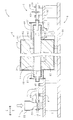
まず、本実施形態のロータリーキルンの構成について説明する。以下の図においては、前側が供給側(上流側)、後側が排出側(下流側)に、それぞれ相当する。図1に、本実施形態のロータリーキルンの前後方向(軸方向)断面図を示す。図1に示すように、本実施形態のロータリーキルン1は、供給部2と、排出部3と、回転部4と、加熱部5と、検出部(図略)と、制御装置(図略)と、表示装置(図略)と、架台9と、を備えている。
<First embodiment>
[Composition of rotary kiln]
First, the structure of the rotary kiln of this embodiment is demonstrated. In the following drawings, the front side corresponds to the supply side (upstream side), and the rear side corresponds to the discharge side (downstream side). In FIG. 1, the front-back direction (axial direction) sectional drawing of the rotary kiln of this embodiment is shown. As shown in FIG. 1, the
{架台9、回転部4}
架台9は、基部90と、供給台91と、排出台92と、を備えている。回転部4は、供給側回転軸40と、供給側ギア41と、供給側ホルダ42と、炉心管43と、排出側回転軸44と、排出側ギア45と、排出側ホルダ46と、を備えている。炉心管43は、カーボン(導体)製であって、前後方向に延びる円筒状を呈している。炉心管43は、略水平に(詳しくは、前側から後側に向かって緩やかに下降するように)、配置されている。炉心管43は、自身の軸周りに回転可能である。電池材料(被処理物)は、炉心管43の内部を、前側から後側に向かって移動する。炉心管43の後端の側周壁には、複数の排出口430が開設されている。
{Stand 9, rotating part 4}
The gantry 9 includes a
供給側ホルダ42は、炉心管43の前端開口を、前側から覆っている。ボルト(図略)により、供給側ホルダ42は、炉心管43に固定されている。供給側回転軸40は、前後方向に延在する円筒状を呈している。供給側回転軸40は、供給側ホルダ42に固定されている。供給側回転軸40は、供給側ホルダ42を貫通している。供給側ギア41は、供給側回転軸40に環装されている。
The
排出側ホルダ46は、炉心管43の後端開口を、後側から覆っている。排出側部材(排出側ホルダ46、排出側回転軸44、排出側ギア45)の配置と、供給側部材(供給側ホルダ42、供給側回転軸40、供給側ギア41)の配置と、は前後対称である。
The
{供給部2、排出部3}
供給部2は、供給台91に配置されている。供給部2は、前後一対の軸受部20と、供給側カバー21と、供給ホッパ22と、スクリューフィーダー23と、を備えている。供給側カバー21は、供給側ホルダ42を前側から覆っている。供給側回転軸40は、供給側カバー21を貫通している。供給ホッパ22は、供給側回転軸40の前側に配置されている。スクリューフィーダー23は、供給ホッパ22の底部から後側に延在している。スクリューフィーダー23は、供給側回転軸40の内部に挿通されている。前後一対の軸受部20は、供給側回転軸40を回転可能に支持している。
{
The
排出部3は、排出台92に配置されている。排出部3は、前後一対の軸受部30と、排出側カバー31と、を備えている。排出側カバー31は、排出側ホルダ46を後側から覆っている。排出側回転軸44は、排出側カバー31を貫通している。排出側カバー31の下端には、排出口310が開設されている。前後一対の軸受部30は、排出側回転軸44を回転可能に支持している。
The
{加熱部5、検出部6、制御装置70、表示装置71}
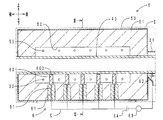
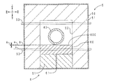
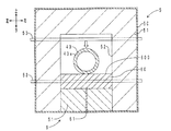
図2に、図1の枠II内の拡大図を示す。図3に、図2のIII−III方向断面図を示す。図1〜図3に示すように、加熱部5は、基部90に配置されている。加熱部5は、供給部2と排出部3との間に配置されている。加熱部5は、外殻50と、断熱材51と、加熱室52と、複数のヒータ53と、を備えている。
{
FIG. 2 shows an enlarged view in the frame II of FIG. FIG. 3 shows a cross-sectional view in the III-III direction of FIG. As shown in FIGS. 1 to 3, the
外殻50は、箱状を呈している。断熱材51は、耐火煉瓦(絶縁体)製であって、外殻50の内面に内張りされている。加熱室52は、断熱材51の内部に区画されている。炉心管43は、加熱室52を、前後方向に貫通している。ヒータ53は、保護管と、電熱式のヒータ本体と、を備えている。ヒータ53は、加熱室52を左右方向に貫通している。複数のヒータ53は、加熱室52に、上下二段に配置されている。上段の複数のヒータ53は、炉心管43の上側に配置されている。上段の複数のヒータ53は、所定間隔ずつ離間して、前後方向に並んでいる。下段の複数のヒータ53は、炉心管43の下側に配置されている。下段の複数のヒータ53は、所定間隔ずつ離間して、前後方向に並んでいる。
The
検出部6は、複数の支持部材60と、複数の電極61と、電極62と、抵抗計63と、電源64と、を備えている。抵抗計63は、本発明の「センサ」の概念に含まれる。支持部材60は、カーボン(導体)製であって、ブロック状を呈している。支持部材60は、加熱室52の底面を区画する断熱材51から、上側に凸設されている。支持部材60は、炉心管43の真下に配置されている。支持部材60は、支持面600を備えている。支持面600は、水平方向に延在する平面状を呈している。支持面600は、下段のヒータ53よりも、高い位置に配置されている。支持面600は、炉心管43よりも、低い位置に配置されている。図3に示すように、炉心管43と支持面600とは、所定の間隔Aだけ離間している。図2に示すように、複数の支持部材60は、所定間隔ずつ離間して、前後方向に並んでいる。
The
ここで、間隔A(つまり支持面600の高度(上下方向位置))は、例えば、炉心管43の質量、炉心管43内部における電池材料の質量、炉心管43の熱変形量、炉心管43の熱による軟化の程度、炉心管43の傾斜角度、炉心管43の回転速度などを考慮して、決定される。また、間隔Aは、試運転、実験、シミュレーションなどにより決定される。支持面600の高度をa、通常運転時に炉心管43に干渉してしまう支持面600の高度をb、下段のヒータ53の最上部の高度をcとすると、高度c<高度a<高度bの関係が成立する。
Here, the distance A (that is, the altitude (the vertical position) of the support surface 600) is, for example, the mass of the
電極61は、上下方向に延在している。電極61の上端は、支持部材60に当接している。図3に示すように、電極61の下端は、外殻50から絶縁された状態で、外殻50の外部に露出している。図2に示すように、電極61は、支持部材60と同数配置されている。複数の電極61は、所定間隔ずつ離間して、前後方向に並んでいる。
The
図2に示すように、電極62は、炉心管43の後端の側周壁の外周面に、下側から接触している。電極62は、パンタグラフ状を呈している。このため、電極62は、炉心管43の変形に追従して、炉心管43との接触状態を確保したまま、変形可能である。
図4に、本実施形態のロータリーキルンの検出回路の模式図を示す。図2、図4に示すように、検出部6と炉心管43との間には、検出回路Cが設定されている。検出回路Cは、電源64と、複数の電極61と、複数の接点Sと、電極62と、抵抗計63と、を経由している。接点Sは、支持部材60と、炉心管43(詳しくは、炉心管43における、任意の支持部材60の真上に配置されている部分)と、を備えている。電源64は、定圧電源である。抵抗計63は、検出回路Cの電気抵抗値Rを検出可能である。電気抵抗値Rは、本発明の「電気量」の概念に含まれる。抵抗計63、制御装置70、表示装置71は、電気的に接続されている。制御装置70の記憶部(図略)には、電気抵抗値Rに関する抵抗しきい値Rthが、格納されている。電気抵抗値Rは、抵抗計63から制御装置70に伝送される。制御装置70は、電気抵抗値Rと、抵抗しきい値Rthと、を比較する。
As shown in FIG. 2, the
In FIG. 4, the schematic diagram of the detection circuit of the rotary kiln of this embodiment is shown. As shown in FIGS. 2 and 4, a detection circuit C is set between the
[電池材料製造時の動き]
次に、本実施形態のロータリーキルンの電池材料製造時の動きについて説明する。まず、モータ(図略)により、図1に示す供給側ギア41および排出側ギア45を回転させる。回転力は、供給側ギア41から、供給側回転軸40、供給側ホルダ42を介して、炉心管43の前端に伝達される。並びに、回転力は、排出側ギア45から、排出側回転軸44、排出側ホルダ46を介して、炉心管43の後端に伝達される。このため、炉心管43は、自身の軸周りに回転する。
[Behavior when manufacturing battery materials]
Next, the movement at the time of battery material manufacture of the rotary kiln of this embodiment is demonstrated. First, the
続いて、スクリューフィーダー23を駆動することにより、電池材料を、供給ホッパ22から炉心管43の内部に供給する。回転する炉心管43の内部において、電池材料は、前側から後側に向かって移動する。図2に示すように、炉心管43の軸方向中間部は、加熱室52に収容されている。炉心管43の軸方向中間部は、加熱室52の複数のヒータ53により、所定の温度パターンで加熱されている。炉心管43の軸方向中間部(つまり加熱室52)を通過させることにより、電池材料に所定の熱処理を施すことができる。
Subsequently, the battery material is supplied from the
その後、熱処理後の電池材料を、回転する炉心管43の排出口430から払い出す。払い出された電池材料は、排出側カバー31の排出口310から取り出される。このようにして、電池材料を製造する。なお、電池材料製造時においては、予め、加熱室52の内部、および炉心管43の内部は、窒素ガス(非酸化性ガス)雰囲気に設定されている。
Thereafter, the battery material after the heat treatment is discharged from the
[炉心管変形時の動き]
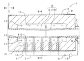
次に、本実施形態のロータリーキルンの炉心管変形時の動きについて説明する。図5に、炉心管変形時(炉心管折損時)における本実施形態のロータリーキルンの加熱部付近の軸方向断面図を示す。図6に、図5のVI−VI方向断面図を示す。図5は図2に、図6は図3に各々対応している。
[Motion during core tube deformation]
Next, the movement of the rotary kiln of the present embodiment when the core tube is deformed will be described. FIG. 5 shows an axial cross-sectional view of the vicinity of the heating section of the rotary kiln of the present embodiment when the core tube is deformed (when the core tube is broken). FIG. 6 is a cross-sectional view in the VI-VI direction of FIG. 5 corresponds to FIG. 2, and FIG. 6 corresponds to FIG.
図3に示すように、通常運転時においては、炉心管43と支持面600との間には、所定の間隔Aが確保されている。このため、炉心管43は、支持面600に干渉しない。したがって、図4に示す全ての接点Sは、開成されている。すなわち、抵抗計63の検出する電気抵抗値Rは、無限大のまま変化しない。よって、通常運転時においては、電気抵抗値Rは、抵抗しきい値Rthを上回り続ける(R>Rth)。
As shown in FIG. 3, during normal operation, a predetermined interval A is secured between the
ここで、図5に示すように、前から三番目の支持部材60と、前から四番目の支持部材60と、の間の区間で炉心管43が折れた場合を想定する。炉心管43が折れると、炉心管43の前側部分43aは、図1に示す一対の軸受部20だけにより、前側から片持ち梁状に支持されることになる。このため、前側部分43aの後端は、重力により落下する。図5、図6に示すように、前側部分43aの後端は、前から三番目の支持部材60の支持面600に当接する。したがって、図4に点線で示すように、前から三番目の接点Sが閉成される。
Here, as shown in FIG. 5, it is assumed that the
同様に、炉心管43が折れると、炉心管43の後側部分43bは、図1に示す一対の軸受部30だけにより、後側から片持ち梁状に支持されることになる。このため、後側部分43bの前端は、重力により落下する。図5に示すように、後側部分43bの前端は、前から四番目の支持部材60の支持面600に当接する。したがって、図4に点線で示すように、前から四番目の接点Sが閉成される。
Similarly, when the
このように、検出回路Cの二つの接点Sが閉成されると、検出回路Cに電流が流れる。このため、抵抗計63の検出する電気抵抗値Rが小さくなる。よって、炉心管43の折損時においては、電気抵抗値Rは、抵抗しきい値Rth以下になる(R≦Rth)。制御装置70は、電気抵抗値Rの変化から、炉心管43が変形したことを判別することができる。制御装置70からの指示により、表示装置71は、画面(図略)に警告のメッセージ(例えば、「炉心管が変形しました」などのメッセージ)を表示する。メッセージは、本発明の「情報」の概念に含まれる。作業者は、当該メッセージを目視することにより、目視できない加熱室52の内部において炉心管43が変形していることを、確認することができる。
Thus, when the two contacts S of the detection circuit C are closed, a current flows through the detection circuit C. For this reason, the electrical resistance value R detected by the
[作用効果]
次に、本実施形態のロータリーキルンの作用効果について説明する。炉心管43や炉心管43の内部の電池材料には、重力が作用している。また、炉心管43や炉心管43の内部の電池材料には、炉心管43の回転に起因する遠心力が作用している。このため、炉心管43は、下側(径方向外側)に変形しやすい。この点、本実施形態のロータリーキルン1によると、図3に示すように、炉心管43の下側に所定の間隔Aだけ離間して、支持部材60が配置されている。図6に示すように、炉心管43が間隔Aを超えて下側に変形すると、炉心管43が支持部材60に当接する。図4に示す抵抗計63は、電気抵抗値Rを介して、支持部材60に対する炉心管43の当接を検出する。このように、本実施形態のロータリーキルン1によると、抵抗計63を介して、加熱室52における炉心管43の変形を、検出することができる。
[Function and effect]
Next, the effect of the rotary kiln of this embodiment is demonstrated. Gravity acts on the
また、図3に示すように、支持面600の高度aは、下段のヒータ53の最上部の高度cよりも、高い位置に設定されている。このため、図5に示すように、炉心管43が変形しても、炉心管43から下段のヒータ53を保護することができる。
Further, as shown in FIG. 3, the altitude a of the
また、図2、図5に示すように、抵抗計63は、加熱室52の外部に配置されている。このため、抵抗計63を、加熱室52の熱から、保護することができる。また、耐熱性の低い安価な抵抗計63を採用することができる。
In addition, as shown in FIGS. 2 and 5, the
また、炉心管43は、カーボン(導体)製である。このため、図4に示すように、変形検出対象である炉心管43を、検出回路Cに組み込むことができる。したがって、炉心管43から独立して検出回路Cを設ける場合と比較して、検出回路Cの回路構成が簡単になる。また、部品点数が少なくなる。
The
また。図4に示すように、表示装置71は、炉心管43の変形に関する警告のメッセージを表示することができる。作業者は、当該メッセージを目視することにより、目視できない加熱室52の内部において炉心管43が変形していることを、確認することができる。したがって、迅速にロータリーキルン1を停止することができる。よって、電池材料が加熱室52内部に漏出し、電池材料に異物が混入することを、抑制することができる。
Also. As shown in FIG. 4, the
また、図2、図5に示すように、電極62は、パンタグラフ状を呈している。このため、電極62は、炉心管43の変形に追従して、炉心管43との接触状態を確保したまま、変形することができる。
As shown in FIGS. 2 and 5, the
また、炉心管43は、カーボン製である。このため、炉心管43が金属(鉄、ステンレス鋼など)製である場合と比較して、電池材料に悪影響を及ぼす金属粉が、電池材料に混入するのを抑制することができる。また、カーボン製の炉心管43は、加工性に優れている。また、カーボン製の炉心管43は、耐熱衝撃性に優れている。
The
また、加熱室52の内部には、窒素ガスが供給されている。このため、炉心管43の外周面が酸化するのを抑制することができる。並びに、炉心管43の内部には、窒素ガスが供給されている。このため、炉心管43の内周面が酸化するのを抑制することができる。
Further, nitrogen gas is supplied into the
また、本実施形態のロータリーキルン1によると、炉心管43ではなく、供給側回転軸40および排出側回転軸44が、回転駆動されている。このため、炉心管43に直接ギアを配置する必要がない。したがって、炉心管43の加工が容易である。
Moreover, according to the
<第二実施形態>
本実施形態のロータリーキルンと、第一実施形態のロータリーキルンとの相違点は、複数の支持部材の各々に対して、個別に検出回路が設定されている点である。ここでは、相違点についてのみ説明する。
<Second embodiment>
The difference between the rotary kiln of this embodiment and the rotary kiln of the first embodiment is that a detection circuit is individually set for each of the plurality of support members. Here, only differences will be described.
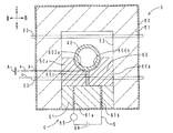
図7に、本実施形態のロータリーキルンの加熱部付近の径方向断面図を示す。図8に、同ロータリーキルンの検出回路の模式図を示す。図9に、炉心管変形時(炉心管折損時)における同ロータリーキルンの加熱部付近の径方向断面図を示す。なお、図3、図4、図6と対応する部位については、同じ符号で示す。 In FIG. 7, radial direction sectional drawing of the heating part vicinity of the rotary kiln of this embodiment is shown. FIG. 8 shows a schematic diagram of a detection circuit of the rotary kiln. FIG. 9 is a radial cross-sectional view of the vicinity of the heating part of the rotary kiln when the core tube is deformed (when the core tube is broken). In addition, about the site | part corresponding to FIG.3, FIG.4, FIG.6, it shows with the same code | symbol.
図7に示すように、支持部材60(図2に示す複数の支持部材60のうち、任意の支持部材60)は、左右一対の支持体60a、60bを備えている。左側の支持体60aの右上隅には、曲面状の支持面600aが凹設されている。右側の支持体60bの左上隅には、曲面状の支持面600bが凹設されている。支持体60a、60bは、カーボン(導体)製である。左右一対の支持体60a、60bの間には、絶縁体製の絶縁板60cが介装されている。絶縁板60cにより、左右一対の支持体60a、60b間の導通は遮断されている。
As shown in FIG. 7, the support member 60 (
電極61aは、上下方向に延在している。電極61aの上端は、左側の支持体60aに当接している。電極61aの下端は、外殻50から絶縁された状態で、外殻50の外部に露出している。同様に、電極61bは、上下方向に延在している。電極61bの上端は、右側の支持体60bに当接している。電極61bの下端は、外殻50から絶縁された状態で、外殻50の外部に露出している。
The
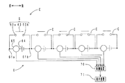
図8に示すように、検出回路Cは、複数の支持部材60の各々に対応して、個別に設定されている。複数の検出回路Cは、各々、電源64と、電流計65と、電極61aと、接点Sと、電極61bと、を経由している。電流計65は、本発明の「センサ」の概念に含まれる。接点Sは、支持体60a、60bと、炉心管43(詳しくは、炉心管43における、任意の支持体60a、60bの真上に配置されている部分)と、を備えている。電流計65は、検出回路Cの電流値Iを検出可能である。電流値Iは、本発明の「電気量」の概念に含まれる。制御装置70の記憶部(図略)には、電流値Iに関する電流しきい値Ithが、格納されている。電流値Iは、電流計65から制御装置70に伝送される。制御装置70は、電流値Iと、電流しきい値Ithと、を比較する。
As shown in FIG. 8, the detection circuit C is individually set corresponding to each of the plurality of
図7に示すように、通常運転時においては、炉心管43と支持面600a、600bとの間には、所定の間隔Aが確保されている。このため、炉心管43は、支持面600a、600bに干渉しない。したがって、図8に示す全ての接点Sは、開成されている。すなわち、電流計65の検出する電流値Iは、0のまま変化しない。よって、通常運転時においては、電流値Iは、電流しきい値Ithを下回り続ける(I<Ith)。
As shown in FIG. 7, during normal operation, a predetermined distance A is secured between the
ここで、図5に示すように、前から三番目の支持部材60と、前から四番目の支持部材60と、の間の区間で炉心管43が折れた場合を想定する。図5、図9に示すように、炉心管43が折れると、炉心管43の前側部分43aの後端は、前から三番目の支持部材60の支持面600に当接する。したがって、支持面600aと支持面600bとが、炉心管43を介して、導通する。すなわち、図8に点線で示すように、前から三番目の検出回路Cの接点Sが閉成される。
Here, as shown in FIG. 5, it is assumed that the
同様に、図5に示すように、炉心管43が折れると、炉心管43の後側部分43bの前端は、前から四番目の支持部材60の支持面600に当接する。したがって、図8に点線で示すように、前から四番目の検出回路Cの接点Sが閉成される。
Similarly, as shown in FIG. 5, when the
このように、二つの検出回路Cの接点Sが閉成されると、二つの検出回路Cにだけ、電流が流れる。このため、二つの検出回路Cの各々において、電流計65の検出する電流値Iが大きくなる。よって、炉心管43の折損時においては、電流値Iは、電流しきい値Ith以上になる(I≧Ith)。制御装置70は、電流値Iの変化から、炉心管43が変形したことを判別することができる。並びに、制御装置70は、電流値Iが変化した二つの検出回路Cの位置から、炉心管43の変形箇所を判別することができる。制御装置70からの指示により、表示装置71は、画面(図略)に警告のメッセージ(例えば、「炉心管の○○部が変形しました」などのメッセージ)を表示する。メッセージは、本発明の「情報」の概念に含まれる。作業者は、当該メッセージを目視することにより、目視できない加熱室52の内部において炉心管43が変形していることを、確認することができる。また、作業者は、炉心管43の変形箇所を、確認することができる。
Thus, when the contact S of the two detection circuits C is closed, current flows only through the two detection circuits C. For this reason, in each of the two detection circuits C, the current value I detected by the
本実施形態のロータリーキルンと、第一実施形態のロータリーキルンとは、構成が共通する部分に関しては、同様の作用効果を有する。また、本実施形態のロータリーキルンによると、複数の支持部材60の各々に対して、個別に検出回路Cが設定されている。このため、作業者は、炉心管43の変形の有無に加えて、炉心管43の変形箇所を、確認することができる。
The rotary kiln according to the present embodiment and the rotary kiln according to the first embodiment have the same functions and effects with respect to parts having the same configuration. Further, according to the rotary kiln of the present embodiment, the detection circuit C is individually set for each of the plurality of
<第三実施形態>
本実施形態のロータリーキルンと、第一実施形態のロータリーキルンとの相違点は、電気式ではなく、機械式の検出部が配置されている点である。ここでは、相違点についてのみ説明する。
<Third embodiment>
The difference between the rotary kiln of this embodiment and the rotary kiln of the first embodiment is that a mechanical detection unit is arranged instead of an electric type. Here, only differences will be described.
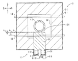
図10に、本実施形態のロータリーキルンの加熱部付近の径方向断面図を示す。図11に、炉心管変形時(炉心管折損時)における同ロータリーキルンの加熱部付近の径方向断面図を示す。なお、図3、図6と対応する部位については、同じ符号で示す。 In FIG. 10, radial direction sectional drawing of the heating part vicinity of the rotary kiln of this embodiment is shown. FIG. 11 is a radial cross-sectional view of the vicinity of the heating part of the rotary kiln when the core tube is deformed (when the core tube is broken). In addition, about the site | part corresponding to FIG. 3, FIG. 6, it shows with the same code | symbol.
図10、図11に示すように、外殻50の下壁開口には、上側に開口する有底筒状のばねケース55が、伏設されている。検出部6は、左右一対のコイルばね66と、シャフト67と、リミットスイッチ68と、を備えている。リミットスイッチ68は、本発明の「センサ」の概念に含まれる。リミットスイッチ68、図4に示す制御装置70、表示装置71は、電気的に接続されている。左右一対のコイルばね66は、ばねケース55の底壁内面と、支持部材60(図2に示す複数の支持部材60のうち、任意の支持部材60)と、の間に介装されている。なお、支持部材60は、耐火煉瓦(絶縁体)製である。リミットスイッチ68は、ばねケース55の底壁外面に配置されている。シャフト67は、ばねケース55の底壁を貫通している。シャフト67は、リミットスイッチ68のレバー680と、支持部材60と、の間に介装されている。
As shown in FIGS. 10 and 11, a bottomed
図10に示すように、通常運転時においては、炉心管43と支持面600との間には、所定の間隔Aが確保されている。このため、炉心管43は、支持面600に干渉しない。したがって、レバー680は揺動しない。
As shown in FIG. 10, during normal operation, a predetermined distance A is secured between the
ここで、図5に示すように、前から三番目の支持部材60と、前から四番目の支持部材60と、の間の区間で炉心管43が折れた場合を想定する。図5、図11に示すように、炉心管43が折れると、炉心管43の前側部分43aの後端は、前から三番目の支持部材60の支持面600に当接する。前側部分43aに上側から押圧されることにより、支持部材60は、左右一対のコイルばね66を圧縮しながら、下側に移動する。また、支持部材60に上側から押圧されることにより、シャフト67は下側に移動する。また、シャフト67に上側から押圧されることにより、レバー680は下側に揺動する。すなわち、リミットスイッチ68がオンになる。同様に、前から四番目の支持部材60に対応するリミットスイッチ68もオンになる。これらのオン信号は、図4に示す制御装置70に伝送される。制御装置70は、オン信号から、炉心管43が変形したことを判別することができる。並びに、制御装置70は、オン信号が伝送された二つのリミットスイッチ68の位置から、炉心管43の変形箇所を判別することができる。制御装置70からの指示により、表示装置71は、画面(図略)に警告のメッセージ(例えば、「炉心管の○○部が変形しました」などのメッセージ)を表示する。メッセージは、本発明の「情報」の概念に含まれる。作業者は、当該メッセージを目視することにより、目視できない加熱室52の内部において炉心管43が変形していることを、確認することができる。また、作業者は、炉心管43の変形箇所を、確認することができる。
Here, as shown in FIG. 5, it is assumed that the
本実施形態のロータリーキルンと、第一実施形態のロータリーキルンとは、構成が共通する部分に関しては、同様の作用効果を有する。また、本実施形態のロータリーキルンによると、複数の支持部材60の各々に対して、個別にリミットスイッチ68が設定されている。このため、作業者は、炉心管43の変形の有無に加えて、炉心管43の変形箇所を、確認することができる。
The rotary kiln according to the present embodiment and the rotary kiln according to the first embodiment have the same functions and effects with respect to parts having the same configuration. Further, according to the rotary kiln of the present embodiment, the
また、本実施形態のロータリーキルンによると、検出回路Cが不要である。このため、検出回路Cの一部に、炉心管43を組み込む必要がない。すなわち、炉心管43が導体製である必要がない(勿論、導体製であってもよい)。したがって、例えばセラミック、石英ガラスなど、絶縁体製の炉心管43であっても、リミットスイッチ68を介して、加熱室52における炉心管43の変形を、検出することができる。
Moreover, according to the rotary kiln of this embodiment, the detection circuit C is unnecessary. For this reason, it is not necessary to incorporate the
また、本実施形態のロータリーキルンによると、検出回路Cが不要である。このため、検出回路Cの一部に、支持部材60を組み込む必要がない。すなわち、支持部材60が導体製である必要がない(勿論、導体製であってもよい)。したがって、支持部材60の材料として、例えばセラミックなどの絶縁体を採用することができる。
Moreover, according to the rotary kiln of this embodiment, the detection circuit C is unnecessary. For this reason, it is not necessary to incorporate the
また、本実施形態のロータリーキルンによると、折損した炉心管43が落下する際に支持部材60に加わる衝撃を、左右一対のコイルばね66が吸収することができる。このため、落下時の衝撃により、炉心管43や支持部材60が破損しにくい。
Further, according to the rotary kiln of the present embodiment, the pair of left and right coil springs 66 can absorb the impact applied to the
<その他>
以上、本発明のロータリーキルンの実施の形態について説明した。しかしながら、実施の形態は上記形態に特に限定されるものではない。当業者が行いうる種々の変形的形態、改良的形態で実施することも可能である。
<Others>
The embodiment of the rotary kiln of the present invention has been described above. However, the embodiment is not particularly limited to the above embodiment. Various modifications and improvements that can be made by those skilled in the art are also possible.
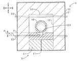
図12に、その他の実施形態(その1)のロータリーキルンの加熱部付近の径方向断面図を示す。なお、図3と対応する部位については、同じ符号で示す。図12に示すように、支持部材60は、加熱室52を、前後方向に並ぶ複数の小部屋に、仕切っている。すなわち、支持部材60は、仕切壁(隔壁)としての機能を有している。本実施形態のロータリーキルンによると、小部屋ごとに、簡単に温度設定をすることができる。このため、加熱室52における温度パターンの設定の自由度が高くなる。
In FIG. 12, radial direction sectional drawing of the heating part vicinity of the rotary kiln of other embodiment (the 1) is shown. In addition, about the site | part corresponding to FIG. 3, it shows with the same code | symbol. As illustrated in FIG. 12, the
なお、図12に示す支持部材60と同様に、図7に示す支持部材60に仕切壁としての機能を持たせるためには、支持部材60の上側のスペースを、支持部材60を上下反転させた形状の支持部材(絶縁板60cを含む)で、埋めればよい。
In addition, like the
図13に、その他の実施形態(その2)のロータリーキルンの加熱部付近の径方向断面図を示す。なお、図3と対応する部位については、同じ符号で示す。図13に示すように、支持面600の曲率は、炉心管43の曲率と、一致している。本実施形態のロータリーキルンによると、図13に一点鎖線で示すように、炉心管43の変形時に、支持面600は、落下してくる炉心管43を、全面的に受け止めることができる。したがって、落下時の衝撃により、炉心管43や支持部材60が破損しにくい。
In FIG. 13, radial direction sectional drawing of the heating part vicinity of the rotary kiln of other embodiment (the 2) is shown. In addition, about the site | part corresponding to FIG. 3, it shows with the same code | symbol. As shown in FIG. 13, the curvature of the
ロータリーキルン1の加熱対象である被処理物の種類は特に限定しない。例えば、各種製品の原料、廃棄物、食品などであってもよい。また、被処理物の性状は特に限定しない。例えば、粉状、粒状、塊状などであってもよい。炉心管43の材質は特に限定しない。導体(カーボン、金属など)製であっても、絶縁体(セラミック、ガラスなど)製であってもよい。
The type of the object to be processed that is the heating target of the
金属製の炉心管と比較して、カーボン製の炉心管43は、靭性が低く、折損しやすい。また、酸化による消耗を抑制するため、カーボン製の炉心管43は、非酸化性ガス雰囲気の加熱室52の内部で加熱する必要がある。よって、カーボン製の炉心管43を採用する場合、靭性が低いにもかかわらず、炉心管43の状態を外部から確認することが困難である。この点、本発明のロータリーキルンによると、カーボン製の炉心管43を採用する場合であっても、加熱室52における炉心管43の状態を、センサ(抵抗計63、電流計65、リミットスイッチ68など)により、簡単に確認することができる。このように、本発明のロータリーキルンは、炉心管43がカーボン製であり、かつ被処理物が金属粉の混入を嫌う物(例えば電池材料)である場合に、特に好適である。
Compared to a metal core tube, the
図3に示す支持部材60と、支持部材60の下側の断熱材51と、の間に、弾性部材(例えば、皿ばね、図10に示すコイルばね66など)を介装してもよい。こうすると、変形した炉心管43が落下する際に支持部材60に加わる衝撃を、弾性部材が吸収することができる。このため、落下時の衝撃により、炉心管43や支持部材60が破損しにくい。また、導体製の弾性部材を、支持部材60と電極61との間に、介装してもよい。こうすると、弾性部材を介して、支持部材60と電極61とを導通させることができる。
An elastic member (for example, a disc spring or a
図2に示す複数の支持部材60の前後方向位置は特に限定しない。例えば、複数の短軸円筒状の管体が合体して炉心管43が形成されている場合、支持部材60を、前後方向に隣り合う一対の管体間の継ぎ目に配置してもよい。すなわち、炉心管43の変形しやすい位置に、重点的に支持部材60を配置してもよい。また、ロータリーキルン1に、単一の支持部材60を配置してもよい。この場合であっても、作業者は、炉心管43の変形の有無を確認することができる。
The front-rear direction positions of the plurality of
図1に示す電極62の位置は特に限定しない。例えば、炉心管43の前端付近、供給側ホルダ42、供給側回転軸40、排出側ホルダ46、排出側回転軸44のいずれかと接触するように、電極62を配置してもよい。電極62はパンタグラフ状でなくてもよい。炉心管43と接触状態を確保できればよい。
The position of the
図4に示す表示装置71がメッセージを表示するタイミング(炉心管43の状態)は特に限定しない。図3に示す間隔Aを小さく設定すると、炉心管43が完全に折損する前に、メッセージを表示することができる。例えば、炉心管43に亀裂が入っただけの段階や、炉心管43が撓んだだけの段階で、メッセージを表示することができる。なお、炉心管43が完全に折損する前の段階においては、炉心管43と支持面600とが、炉心管43の回転角度に応じて、周期的に接触、離間を繰り返す場合がある。この場合、電気抵抗値Rは、周期的に変化することになる。制御装置70は、当該電気抵抗値Rの周期的な変化を基に、表示装置71にメッセージ表示の指示を出してもよい。図3に示す間隔Aを大きく設定すると、炉心管43が完全に折損した後に、メッセージを表示することができる。
The timing at which the
表示装置71は、メッセージの代わりに、あるいはメッセージと共に、マーク、図形を表示してもよい。また、表示装置71は、メッセージの代わりに、あるいはメッセージと共に、ランプを点灯あるいは点滅させてもよい。また、表示装置71は、メッセージの代わりに、あるいはメッセージと共に、警報を鳴らしてもよい。
The
制御装置70は、表示装置71にメッセージを表示させなくてもよい。例えば、炉心管43の変形時に、制御装置70は、ロータリーキルン1の運転を自動停止してもよい。すなわち、制御装置70は、インターロック制御を行ってもよい。
The
図8に示す複数の検出回路Cの電源64、電流計65は、共用化してもよい。すなわち、単一の電源64により、複数の検出回路Cに、走査的に、順次、電圧を加えてもよい。同様に、単一の電流計65に、複数の検出回路Cを、走査的に、順次、接続してもよい。
The
図4に示す接点Sは、通常運転時において閉成され、変形時に開成されてもよい。例えば、炉心管43の前後方向両端(供給側ホルダ42、供給側回転軸40、排出側ホルダ46、排出側回転軸44を含む)に一対の電極を配置し、通常運転時において、一対の電極間に電流を流せばよい。変形時においては、接点Sが開成される(完全に導通が遮断されなくてもよい)。このため、炉心管43の導通面積が小さくなる。したがって、電気抵抗値Rが大きくなる。当該電気抵抗値Rの変化を抵抗計63で検出することにより、炉心管43の変形を検出してもよい。
The contact S shown in FIG. 4 may be closed during normal operation and may be opened during deformation. For example, a pair of electrodes are disposed at both ends in the front-rear direction of the core tube 43 (including the
図10に示すコイルばね66の周囲に、コイルばね66の最大圧縮量を規制するストッパを配置してもよい。こうすると、図11に示す炉心管43落下時において、支持面600の高度aが下段のヒータ53の高度cを下回ることを、防止することができる。このため、炉心管43から下段のヒータ53を確実に保護することができる。また、ストッパの規制量を調整することにより、支持面600の最大下降量を、リミットスイッチ68のレバー680の上下方向のストローク量以下に設定することができる。こうすると、シャフト67(つまり炉心管43)からレバー680を保護することができる。
A stopper that restricts the maximum compression amount of the
図10に示すリミットスイッチ68の代わりに、センサとして、歪みゲージ、荷重センサなどの接触式センサを配置してもよい。また、近接センサなどの非接触式センサを配置してもよい。
Instead of the
1:ロータリーキルン、2:供給部、20:軸受部、21:供給側カバー、22:供給ホッパ、23:スクリューフィーダー、3:排出部、30:軸受部、31:排出側カバー、310:排出口、4:回転部、40:供給側回転軸、41:供給側ギア、42:供給側ホルダ、43:炉心管、43a:前側部分、43b:後側部分、430:排出口、44:排出側回転軸、45:排出側ギア、46:排出側ホルダ、5:加熱部、50:外殻、51:断熱材、52:加熱室、53:ヒータ、55:ばねケース、6:検出部、60:支持部材、60a:支持体、60b:支持体、60c:絶縁板、600:支持面、600a:支持面、600b:支持面、61:電極、61a:電極、61b:電極、62:電極、63:抵抗計(センサ)、64:電源、65:電流計(センサ)、66:コイルばね、67:シャフト、68:リミットスイッチ(センサ)、680:レバー、70:制御装置、71:表示装置、9:架台、90:基部、91:供給台、92:排出台、A:間隔、C:検出回路、S:接点、a〜c:高度 1: rotary kiln, 2: supply part, 20: bearing part, 21: supply side cover, 22: supply hopper, 23: screw feeder, 3: discharge part, 30: bearing part, 31: discharge side cover, 310: discharge port 4, rotating part, 40: supply side rotating shaft, 41: supply side gear, 42: supply side holder, 43: core tube, 43a: front side part, 43b: rear side part, 430: discharge port, 44: discharge side Rotation shaft, 45: discharge side gear, 46: discharge side holder, 5: heating unit, 50: outer shell, 51: heat insulating material, 52: heating chamber, 53: heater, 55: spring case, 6: detection unit, 60 : Support member, 60a: support, 60b: support, 60c: insulating plate, 600: support surface, 600a: support surface, 600b: support surface, 61: electrode, 61a: electrode, 61b: electrode, 62: electrode, 63: Resistance meter (sensor), 64: Electricity , 65: ammeter (sensor), 66: coil spring, 67: shaft, 68: limit switch (sensor), 680: lever, 70: control device, 71: display device, 9: mount, 90: base, 91: Supply stand, 92: Discharge stand, A: Interval, C: Detection circuit, S: Contact, ac: Altitude
Claims (6)
前記炉心管が挿通される加熱室を有する加熱部と、
前記加熱室の内部に配置され、前記炉心管の下側に所定間隔だけ離間して配置され、前記所定間隔を超えて下側に変形した前記炉心管を支持可能な支持部材と、
変形した前記炉心管が前記支持部材に当接したことを検出するセンサと、
を備えるロータリーキルン。 A core tube that rotates around its own axis;
A heating section having a heating chamber through which the core tube is inserted;
A support member that is disposed inside the heating chamber, is disposed at a predetermined interval below the core tube, and is capable of supporting the core tube deformed downward beyond the predetermined interval;
A sensor for detecting that the deformed core tube is in contact with the support member;
Rotary kiln with
前記支持部材は、前記炉心管を支持可能な支持面を有し、
前記支持面は、前記ヒータよりも高い位置に配置される請求項1に記載のロータリーキルン。 The heating unit is disposed inside the heating chamber, and has a heater for heating the core tube from below.
The support member has a support surface capable of supporting the core tube,
The rotary kiln according to claim 1, wherein the support surface is disposed at a position higher than the heater.
さらに、前記炉心管の少なくとも一部と、前記支持部材と、電源と、を経由する検出回路を備え、
前記センサは、前記炉心管が前記支持部材に当接し、前記検出回路の接点が閉成または開成した際の、電気量の変化を検出する請求項1ないし請求項3のいずれかに記載のロータリーキルン。 The core tube and the support member are both made of a conductor,
And a detection circuit that passes through at least a part of the core tube, the support member, and a power source,
The rotary kiln according to any one of claims 1 to 3, wherein the sensor detects a change in the amount of electricity when the furnace core tube abuts on the support member and a contact of the detection circuit is closed or opened. .
前記センサは、前記炉心管が前記支持部材に当接した際の、前記支持部材の移動を検出する請求項1ないし請求項3のいずれかに記載のロータリーキルン。 The support member is movable downward;
The rotary kiln according to any one of claims 1 to 3, wherein the sensor detects movement of the support member when the furnace core tube contacts the support member.
前記制御装置は、前記センサが検出した信号を基に前記炉心管の状態を判別し、
前記表示装置は、前記制御装置の判別結果に関する情報を表示する請求項1ないし請求項5のいずれかに記載のロータリーキルン。 And a control device electrically connected to the sensor, and a display device electrically connected to the control device,
The control device determines the state of the core tube based on the signal detected by the sensor,
The rotary kiln according to any one of claims 1 to 5, wherein the display device displays information related to a determination result of the control device.
Priority Applications (1)
| Application Number | Priority Date | Filing Date | Title |
|---|---|---|---|
| JP2016070345A JP6591925B2 (en) | 2016-03-31 | 2016-03-31 | Rotary kiln |
Applications Claiming Priority (1)
| Application Number | Priority Date | Filing Date | Title |
|---|---|---|---|
| JP2016070345A JP6591925B2 (en) | 2016-03-31 | 2016-03-31 | Rotary kiln |
Publications (2)
| Publication Number | Publication Date |
|---|---|
| JP2017180979A JP2017180979A (en) | 2017-10-05 |
| JP6591925B2 true JP6591925B2 (en) | 2019-10-16 |
Family
ID=60004162
Family Applications (1)
| Application Number | Title | Priority Date | Filing Date |
|---|---|---|---|
| JP2016070345A Active JP6591925B2 (en) | 2016-03-31 | 2016-03-31 | Rotary kiln |
Country Status (1)
| Country | Link |
|---|---|
| JP (1) | JP6591925B2 (en) |
Families Citing this family (2)
| Publication number | Priority date | Publication date | Assignee | Title |
|---|---|---|---|---|
| CN113188333B (en) * | 2021-03-26 | 2022-07-15 | 遂宁市百虎湾建材有限责任公司 | A kind of roasting equipment for shale brick production |
| CN115084721B (en) * | 2022-05-20 | 2025-06-17 | 三一技术装备有限公司 | Electric core preheating device and battery production line |
Family Cites Families (4)
| Publication number | Priority date | Publication date | Assignee | Title |
|---|---|---|---|---|
| JP2943956B2 (en) * | 1992-11-20 | 1999-08-30 | 宇部興産株式会社 | Centering method for horizontal rotating cylinder |
| JPH0786194A (en) * | 1993-09-09 | 1995-03-31 | Sansha Electric Mfg Co Ltd | Diffusion furnace with silicon carbide furnace core tube |
| JPH10148469A (en) * | 1996-11-20 | 1998-06-02 | Mitsubishi Chem Corp | Externally heated rotary kiln and method for producing powdery granular high-purity material using the same |
| JP2007187430A (en) * | 2005-12-13 | 2007-07-26 | Tdk Corp | Rotary kiln |
-
2016
- 2016-03-31 JP JP2016070345A patent/JP6591925B2/en active Active
Also Published As
| Publication number | Publication date |
|---|---|
| JP2017180979A (en) | 2017-10-05 |
Similar Documents
| Publication | Publication Date | Title |
|---|---|---|
| JP6591925B2 (en) | Rotary kiln | |
| JP2005533357A (en) | Magnetic sensing thermostat control | |
| JP6435112B2 (en) | Spinning molding equipment | |
| US1069255A (en) | Glass furnace and process. | |
| JP6533911B1 (en) | Electromagnetic induction heating device | |
| JP2019534237A (en) | High temperature glass melting container | |
| EP1536444A1 (en) | On-load disconnector for power lines, particularly for railroad power lines | |
| JP2002316033A (en) | mixer | |
| US3549943A (en) | Rotating electrode and gas arc heater employing the same | |
| CN203866611U (en) | Electric iron temperature controller | |
| US1415989A (en) | House electric | |
| US9781774B1 (en) | Heating element and fusion furnace comprising same | |
| US3440322A (en) | Electrical resistance furnaces | |
| CN101644536A (en) | Vacuum heating furnace for smelting spongy titanium and spongy zirconium | |
| US701577A (en) | Lightning-conductor. | |
| US832511A (en) | Electric furnace. | |
| JP2011019714A (en) | Electric rotary hook | |
| US255885A (en) | Thermo-electric battery | |
| CN113905463A (en) | Quartz electric heating tube embedded with thermal fuse | |
| CN218936981U (en) | Rotary kiln convenient for crushing materials | |
| TWI637140B (en) | Electric arc furnace | |
| JP2009272230A (en) | Throw-in type heater | |
| CN210453378U (en) | Overheating protection device and blade mold including the same | |
| US129867A (en) | John e | |
| US1242275A (en) | Electric furnace. |
Legal Events
| Date | Code | Title | Description |
|---|---|---|---|
| A621 | Written request for application examination |
Free format text: JAPANESE INTERMEDIATE CODE: A621 Effective date: 20181205 |
|
| A977 | Report on retrieval |
Free format text: JAPANESE INTERMEDIATE CODE: A971007 Effective date: 20190821 |
|
| TRDD | Decision of grant or rejection written | ||
| A01 | Written decision to grant a patent or to grant a registration (utility model) |
Free format text: JAPANESE INTERMEDIATE CODE: A01 Effective date: 20190827 |
|
| A61 | First payment of annual fees (during grant procedure) |
Free format text: JAPANESE INTERMEDIATE CODE: A61 Effective date: 20190919 |
|
| R150 | Certificate of patent or registration of utility model |
Ref document number: 6591925 Country of ref document: JP Free format text: JAPANESE INTERMEDIATE CODE: R150 |
|
| R250 | Receipt of annual fees |
Free format text: JAPANESE INTERMEDIATE CODE: R250 |
|
| R250 | Receipt of annual fees |
Free format text: JAPANESE INTERMEDIATE CODE: R250 |