JP6593006B2 - Fixing device - Google Patents
Fixing device Download PDFInfo
- Publication number
- JP6593006B2 JP6593006B2 JP2015146420A JP2015146420A JP6593006B2 JP 6593006 B2 JP6593006 B2 JP 6593006B2 JP 2015146420 A JP2015146420 A JP 2015146420A JP 2015146420 A JP2015146420 A JP 2015146420A JP 6593006 B2 JP6593006 B2 JP 6593006B2
- Authority
- JP
- Japan
- Prior art keywords
- endless belt
- guide
- nip
- gap forming
- inclined surface
- Prior art date
- Legal status (The legal status is an assumption and is not a legal conclusion. Google has not performed a legal analysis and makes no representation as to the accuracy of the status listed.)
- Active
Links
- 230000002093 peripheral effect Effects 0.000 claims description 27
- 239000000314 lubricant Substances 0.000 claims description 17
- 238000000034 method Methods 0.000 claims description 4
- 239000004519 grease Substances 0.000 description 19
- 238000011144 upstream manufacturing Methods 0.000 description 14
- 229910052736 halogen Inorganic materials 0.000 description 9
- 150000002367 halogens Chemical class 0.000 description 9
- 238000012546 transfer Methods 0.000 description 8
- 229920005989 resin Polymers 0.000 description 6
- 239000011347 resin Substances 0.000 description 6
- 239000010410 layer Substances 0.000 description 5
- 238000012986 modification Methods 0.000 description 5
- 230000004048 modification Effects 0.000 description 5
- 239000000428 dust Substances 0.000 description 4
- 238000005461 lubrication Methods 0.000 description 4
- 229910052751 metal Inorganic materials 0.000 description 4
- 239000002184 metal Substances 0.000 description 4
- 229910052782 aluminium Inorganic materials 0.000 description 3
- XAGFODPZIPBFFR-UHFFFAOYSA-N aluminium Chemical compound [Al] XAGFODPZIPBFFR-UHFFFAOYSA-N 0.000 description 3
- 238000004140 cleaning Methods 0.000 description 3
- 230000008569 process Effects 0.000 description 3
- YCKRFDGAMUMZLT-UHFFFAOYSA-N Fluorine atom Chemical compound [F] YCKRFDGAMUMZLT-UHFFFAOYSA-N 0.000 description 2
- 229920000106 Liquid crystal polymer Polymers 0.000 description 2
- 239000004977 Liquid-crystal polymers (LCPs) Substances 0.000 description 2
- 239000004642 Polyimide Substances 0.000 description 2
- 229910000831 Steel Inorganic materials 0.000 description 2
- 238000013459 approach Methods 0.000 description 2
- 238000005452 bending Methods 0.000 description 2
- 229910052731 fluorine Inorganic materials 0.000 description 2
- 239000011737 fluorine Substances 0.000 description 2
- 238000010438 heat treatment Methods 0.000 description 2
- 239000000463 material Substances 0.000 description 2
- 230000007246 mechanism Effects 0.000 description 2
- 230000035515 penetration Effects 0.000 description 2
- 229920001721 polyimide Polymers 0.000 description 2
- 230000001105 regulatory effect Effects 0.000 description 2
- 238000000926 separation method Methods 0.000 description 2
- 239000010959 steel Substances 0.000 description 2
- 230000001154 acute effect Effects 0.000 description 1
- 230000008901 benefit Effects 0.000 description 1
- 230000015572 biosynthetic process Effects 0.000 description 1
- 239000011248 coating agent Substances 0.000 description 1
- 238000000576 coating method Methods 0.000 description 1
- 238000011161 development Methods 0.000 description 1
- 230000018109 developmental process Effects 0.000 description 1
- 238000007599 discharging Methods 0.000 description 1
- 230000012447 hatching Effects 0.000 description 1
- 229920006015 heat resistant resin Polymers 0.000 description 1
- 238000000691 measurement method Methods 0.000 description 1
- 108091008695 photoreceptors Proteins 0.000 description 1
- 239000004810 polytetrafluoroethylene Substances 0.000 description 1
- 229920001343 polytetrafluoroethylene Polymers 0.000 description 1
- 238000003825 pressing Methods 0.000 description 1
- 239000011241 protective layer Substances 0.000 description 1
- 238000003860 storage Methods 0.000 description 1
- 239000000758 substrate Substances 0.000 description 1
- 239000002344 surface layer Substances 0.000 description 1
Images


Landscapes
- Fixing For Electrophotography (AREA)
Description
本発明は、記録シートに現像剤像を熱定着するための定着装置に関する。 The present invention relates to a fixing device for thermally fixing a developer image on a recording sheet.
用紙などの記録シートに現像剤像を熱定着するための定着装置として、特許文献1には、エンドレスベルトと、エンドレスベルトの内周面に摺接するニップ部材と、エンドレスベルトとの間にニップを形成する加圧ローラと、エンドレスベルトの回転方向におけるニップの下流側に配置され、ニップ部材と加圧ローラとの間から出たエンドレスベルトをガイドするガイド部材とを備えたものが開示されている。
As a fixing device for thermally fixing a developer image on a recording sheet such as paper,
この定着装置は、ガイド部材が、エンドレスベルトをガイドする下流ガイドと、ニップと下流ガイドとの間に設けられた凹部とを有し、凹部によってエンドレスベルトとガイド部材との間にギャップが形成されるように構成されている。これにより、エンドレスベルトの熱がガイド部材に奪われることを抑えたり、エンドレスベルトとガイド部材との摺動抵抗を小さくしたりすることができるようになっている。 In this fixing device, the guide member has a downstream guide that guides the endless belt, and a recess provided between the nip and the downstream guide, and the recess forms a gap between the endless belt and the guide member. It is comprised so that. As a result, the heat of the endless belt can be prevented from being taken away by the guide member, and the sliding resistance between the endless belt and the guide member can be reduced.
ところで、エンドレスベルトとニップ部材などとの間には潤滑剤が介在しているため、エンドレスベルトの内周面に付着している潤滑剤がガイド部材の凹部で掻き取られて凹部内に入り込むことがある。凹部内に入り込んだ潤滑剤のうち、エンドレスベルト近くの潤滑剤は、エンドレスベルトに引き連れられて再び潤滑に利用されることとなるが、エンドレスベルトから離れたところにある潤滑剤は、凹部内に留まり続けて潤滑に利用されなくなる可能性がある。そして、潤滑剤の一部が潤滑に利用されなくなると、例えば、エンドレスベルトとニップ部材などとの間の潤滑剤の量が十分でなくなるなどして、エンドレスベルトの摺動抵抗が増大してしまうおそれがある。 By the way, since the lubricant is interposed between the endless belt and the nip member, the lubricant adhering to the inner peripheral surface of the endless belt is scraped off by the recess of the guide member and enters the recess. There is. Of the lubricant that has entered the recess, the lubricant near the endless belt will be pulled back to the endless belt and used again for lubrication, but the lubricant away from the endless belt will remain in the recess. It may stay and not be used for lubrication. If a part of the lubricant is no longer used for lubrication, for example, the amount of lubricant between the endless belt and the nip member becomes insufficient, and the sliding resistance of the endless belt increases. There is a fear.
本発明は、以上の背景に鑑みてなされたものであり、エンドレスベルトの摺動抵抗の増大を抑制することができる定着装置を提供することを目的とする。 SUMMARY An advantage of some aspects of the invention is that it provides a fixing device that can suppress an increase in sliding resistance of an endless belt.
前記した目的を達成するため、本発明の定着装置は、エンドレスベルトと、前記エンドレスベルトの内周面に配置された潤滑剤と、前記エンドレスベルトの内周面に摺接する摺接部を有するニップ部材と、前記ニップ部材との間で前記エンドレスベルトを挟み、前記エンドレスベルトとの間にニップを形成するバックアップ部材と、前記エンドレスベルトの回転方向における前記ニップの下流側に配置され、前記ニップ部材と前記バックアップ部材との間から出た前記エンドレスベルトをガイドするガイド部材と、を備える。
前記ガイド部材は、前記エンドレスベルトの内周面に摺接して前記エンドレスベルトをガイドするガイド部と、前記回転方向における前記ニップと前記ガイド部との間に設けられ、前記エンドレスベルトとの間にギャップを形成するギャップ形成部と、を有する。
前記ギャップ形成部は、当該ギャップ形成部の前記回転方向における下流端から少なくとも所定の範囲の部分に前記エンドレスベルトに近づくように延びて前記ガイド部につながる傾斜面を有する。
前記傾斜面は、前記エンドレスベルトとの間で前記潤滑剤が溜まる範囲では、前記摺接部の前記回転方向における下流端と前記ガイド部とに接する平面に対する最大傾斜角が90°未満である。
In order to achieve the above-described object, a fixing device of the present invention includes an endless belt, a lubricant disposed on an inner peripheral surface of the endless belt, and a nip having a sliding contact portion that is in sliding contact with the inner peripheral surface of the endless belt. A backup member that sandwiches the endless belt between a member and the nip member, and forms a nip between the endless belt, and a nip member disposed downstream of the nip in the rotational direction of the endless belt, And a guide member for guiding the endless belt that has come out between the backup member and the backup member.
The guide member is provided between a guide portion that slides in contact with an inner peripheral surface of the endless belt and guides the endless belt, and the nip and the guide portion in the rotation direction. A gap forming portion for forming a gap.
The gap forming portion has an inclined surface extending from the downstream end of the gap forming portion in the rotation direction to at least a predetermined range so as to approach the endless belt and connected to the guide portion.
In the range where the lubricant accumulates between the inclined surface and the endless belt, a maximum inclination angle with respect to a plane contacting the downstream end of the sliding contact portion in the rotation direction and the guide portion is less than 90 °.
また、前記した目的を達成するため、本発明の定着装置は、エンドレスベルトと、前記エンドレスベルトの内周面に配置された潤滑剤と、前記エンドレスベルトの内周面に摺接する摺接部を有するニップ部材と、前記ニップ部材との間で前記エンドレスベルトを挟み、前記エンドレスベルトとの間にニップを形成するバックアップ部材と、前記エンドレスベルトの回転方向における前記ニップの下流側に配置され、前記ニップ部材と前記バックアップ部材との間から出た前記エンドレスベルトをガイドするガイド部材と、を備える。
前記ガイド部材は、前記エンドレスベルトの内周面に摺接して前記エンドレスベルトをガイドするガイド部と、前記回転方向における前記ニップと前記ガイド部との間に設けられ、前記エンドレスベルトとの間にギャップを形成するギャップ形成部と、を有する。
前記ギャップ形成部は、当該ギャップ形成部の前記回転方向における下流端から少なくとも所定の範囲の部分に前記エンドレスベルトに近づくように延びて前記ガイド部につながる傾斜面を有する。
前記傾斜面は、前記ギャップ形成部の前記回転方向における下流端から2mmの範囲では、前記摺接部の前記回転方向における下流端と前記ガイド部とに接する平面に対する最大傾斜角が90°未満である。
In order to achieve the above object, the fixing device of the present invention includes an endless belt, a lubricant disposed on the inner peripheral surface of the endless belt, and a sliding contact portion that is in sliding contact with the inner peripheral surface of the endless belt. A backup member that sandwiches the endless belt between the nip member and the nip member and forms a nip with the endless belt, and is disposed downstream of the nip in the rotation direction of the endless belt, A guide member that guides the endless belt that has come out between the nip member and the backup member.
The guide member is provided between a guide portion that slides in contact with an inner peripheral surface of the endless belt and guides the endless belt, and the nip and the guide portion in the rotation direction. A gap forming portion for forming a gap.
The gap forming portion has an inclined surface extending from the downstream end of the gap forming portion in the rotation direction to at least a predetermined range so as to approach the endless belt and connected to the guide portion.
In the range of 2 mm from the downstream end in the rotation direction of the gap forming portion, the inclined surface has a maximum inclination angle with respect to a plane contacting the downstream end in the rotation direction of the sliding contact portion and the guide portion is less than 90 °. is there.
このような構成によれば、エンドレスベルトと傾斜面との間に溜まった潤滑剤を、エンドレスベルトの回転により傾斜面に沿わせてエンドレスベルトの内周面に移動させることができるので、エンドレスベルトの内周面への潤滑剤の供給能力を向上させることができる。これにより、エンドレスベルトとニップ部材などとの間に十分な潤滑剤を介在させることができるので、エンドレスベルトの摺動抵抗の増大を抑制することができる。 According to such a configuration, the lubricant accumulated between the endless belt and the inclined surface can be moved to the inner peripheral surface of the endless belt along the inclined surface by rotation of the endless belt. It is possible to improve the supply capability of the lubricant to the inner peripheral surface. Thereby, since a sufficient lubricant can be interposed between the endless belt and the nip member, an increase in sliding resistance of the endless belt can be suppressed.
前記した定着装置において、前記ギャップ形成部は、凹部であり、その最大深さは、0.7mm以上である構成とすることができる。 In the fixing device described above, the gap forming portion may be a concave portion, and the maximum depth may be 0.7 mm or more.
前記した定着装置において、前記ギャップ形成部の前記回転方向における長さは、0.7mm以上5.2mm以下である構成とすることができる。 In the fixing device described above, a length of the gap forming portion in the rotation direction may be 0.7 mm or more and 5.2 mm or less.
前記した定着装置において、前記傾斜面は、前記ギャップ形成部の前記回転方向における全範囲にわたって設けられている構成とすることができる。 In the fixing device described above, the inclined surface may be provided over the entire range in the rotation direction of the gap forming portion.
前記した定着装置において、前記傾斜面は、平面状である構成とすることができる。 In the above-described fixing device, the inclined surface may be planar.
また、前記した定着装置において、前記傾斜面は、前記エンドレスベルトの幅方向から見た断面形状が前記エンドレスベルトに近づく方向に凸となる、曲面状である構成とすることもできる。 In the fixing device described above, the inclined surface may have a curved surface shape in which a cross-sectional shape viewed from the width direction of the endless belt is convex in a direction approaching the endless belt.
また、前記した定着装置において、前記傾斜面は、前記エンドレスベルトの幅方向から見た断面形状が前記エンドレスベルトから離れる方向に凹となる、曲面状である構成とすることができる。 In the fixing device described above, the inclined surface may have a curved surface shape in which a cross-sectional shape viewed from the width direction of the endless belt is concave in a direction away from the endless belt.
本発明によれば、エンドレスベルトの摺動抵抗の増大を抑制することができる。 According to the present invention, an increase in sliding resistance of the endless belt can be suppressed.
次に、本発明の実施形態について、適宜図面を参照しながら詳細に説明する。なお、以下の説明において、特に断りがないかぎり図1に示した上下方向を上下、図1における左側を前、右側を後、紙面の奥側を左、紙面の手前側を右として、各方向を示す。ここでの左右は、カラーレーザプリンタ1の前側に立った者から見た方向を基準として規定してある。
Next, embodiments of the present invention will be described in detail with reference to the drawings as appropriate. In the following description, unless otherwise specified, the vertical direction shown in FIG. 1 is up and down, the left side in FIG. 1 is front, the right side is rear, the back side of the paper is left, and the front side of the paper is right. Indicates. Here, the left and right are defined based on the direction viewed from the person standing on the front side of the
<カラーレーザプリンタの概略構成>
図1に示すように、カラーレーザプリンタ1は、装置本体2内に、用紙51(記録シート)を供給する給紙部5と、給紙された用紙51に画像を形成する画像形成部6と、画像が形成された用紙51を排出する排紙部7とを備えている。このプリンタ1は、用紙51を50ppm(pages per minute)のスループットにて、画像が形成された用紙51を排出(出力)する。プリンタ1のスループットは、30〜80ppmの範囲であってもよいし、40〜60ppmの範囲であっても良い。
<Schematic configuration of color laser printer>
As shown in FIG. 1, the
給紙部5は、装置本体2内の下方において、装置本体2に対して前側からスライド操作により脱着される給紙トレイ50と、給紙トレイ50から用紙51を前側から上に持ち上げ、後側へ反転させて搬送する給紙機構M1とからなる。
In the lower part of the apparatus main body 2, the paper supply unit 5 lifts the
この給紙機構M1は、給紙トレイ50の前側端部の付近に設けられた、ピックアップローラ52、分離ローラ53、分離パッド54などからなり、これらにより給紙トレイ50にある用紙51が一枚ずつ分離されて上方へ送られる。上方へ向けて搬送された用紙51は、紙粉取りローラ55とピンチローラ56の間を通過した後、搬送経路57を通って後向きへ方向転換され、後述する搬送ベルト73の上に供給される。用紙51が、紙粉取りローラ55とピンチローラ56の間を通過しているとき、用紙51に付着した紙粉は、紙粉取りローラ55により用紙51から取り除かれる。
The paper feed mechanism M1 includes a
画像形成部6は、スキャナ部61、プロセス部62、転写部63および定着装置100を備えている。
The image forming unit 6 includes a
スキャナ部61は、装置本体2の上部に設けられており、図示はしないが、レーザ発光部、ポリゴンミラー、複数のレンズおよび反射鏡を備えている。スキャナ部61では、シアン、マゼンタ、イエロー、ブラックの各色に対応させてレーザ発光部から発光されるレーザをポリゴンミラーで左右方向に高速で走査させ、複数のレンズおよび反射鏡を通過または反射させた後各感光体ドラム31に照射している(破線参照)。
The
プロセス部62は、スキャナ部61の下方で、給紙部5の上方に配置されており、装置本体2に対して前後方向に移動可能となる感光体ユニット3を備えている。感光体ユニット3は、ドラムサブユニット30と、ドラムサブユニット30に装着される現像カートリッジ40とを備えている。
The
ドラムサブユニット30は、公知の感光体ドラム31やスコロトロン型帯電器32などを備えている。
現像カートリッジ40は、内部にトナー(現像剤)が収容されており、公知の供給ローラ41や現像ローラ42や層厚規制ブレード43などを備えている。
The
The developing
このようなプロセス部62は、次のように機能する。現像カートリッジ40内のトナーが供給ローラ41により現像ローラ42へ供給され、このときトナーが、供給ローラ41と現像ローラ42との間で正極性に摩擦帯電される。現像ローラ42に供給されたトナーは、現像ローラ42の回転に伴って層厚規制ブレード43によって擦られ、一定厚さの薄層として現像ローラ42の表面に担持される。
Such a
一方、ドラムサブユニット30では、スコロトロン型帯電器32がコロナ放電により感光体ドラム31を一様に正極性に帯電させる。この帯電した感光体ドラム31にスキャナ部61からのレーザが照射されて、用紙51に形成すべき画像に対応した静電潜像が感光体ドラム31に形成される。
On the other hand, in the
さらに感光体ドラム31が回転すると、現像ローラ42に担持されているトナーが感光体ドラム31の静電潜像、すなわち、一様に正帯電されている感光体ドラム31の表面のうち、レーザにより露光され電位が下がった部分に供給される。これにより、感光体ドラム31の静電潜像は可視像化され、感光体ドラム31の表面には、各色のトナーに対応して、反転現像によるトナー像が担持される。
When the
転写部63は、駆動ローラ71、従動ローラ72、搬送ベルト73、転写ローラ74およびクリーニング部75を備えている。
駆動ローラ71および従動ローラ72は、前後に離れて平行に配置され、これらにエンドレスベルトからなる搬送ベルト73が巻き掛けられている。搬送ベルト73は、その外側の面が各感光体ドラム31に接している。そして、搬送ベルト73の内側には各感光体ドラム31との間で搬送ベルト73を挟み込む転写ローラ74が配置されている。転写ローラ74には、図示しない高圧基板から転写バイアスが印加される。画像形成時には、搬送ベルト73により搬送されてきた用紙51は、感光体ドラム31と転写ローラ74に挟持され、感光体ドラム31上のトナー像が用紙51に転写される。
The
The driving
クリーニング部75は、搬送ベルト73の下方に配置され、搬送ベルト73に付着したトナーを除去し、その下方に配置されたトナー貯留部76に除去したトナーを落下させるようになっている。
The
定着装置100は、転写部63の後方に設けられ、用紙51上に転写されたトナー像を用紙51上に熱定着する。なお、定着装置100については、後で詳述する。
The fixing
排紙部7において、用紙51の排紙側搬送経路91は、定着装置100の出口から上方へ向かって延び前側に反転するように形成されている。排紙側搬送経路91の途中には、用紙51を搬送する複数の搬送ローラ92が配置されている。装置本体2の上面には、印刷後の用紙51を蓄積する排紙トレイ93が形成されており、搬送ローラ92により排紙側搬送経路91から排出された用紙51は、排紙トレイ93に蓄積される。
In the paper discharge unit 7, the paper discharge
<定着装置の詳細構成>
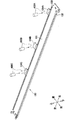
図2に示すように、定着装置100は、エンドレスベルトの一例としての定着ベルト110と、ハロゲンランプ120(発熱体)と、ニップ部材の一例としてのニップ板130と、バックアップ部材の一例としての加圧ローラ140と、反射板150と、ステイ160と、樹脂製のカバー部材200とを主に備えている。加圧ローラ140が回転することにより、用紙51は定着装置100を300mm/秒の速さで搬送される。用紙51が定着装置100を搬送される速度は、200〜800mm/秒の範囲であっても良いし、200〜600mm/秒の範囲であっても良いし、250〜350mm/秒の範囲であっても良い。
<Detailed configuration of fixing device>
As shown in FIG. 2, the fixing
定着ベルト110は、耐熱性と可撓性を有する無端状(筒状)のベルトであり、カバー部材200に形成されたガイド(上流ガイド310、下流ガイド320および端部ガイド330,340)により回転が案内されている。具体的に、本実施形態においては、定着ベルト110は、金属製の基材と、基材の外周に被覆された樹脂とを有する金属ベルトとして構成されている。この定着ベルト110は、基材の主成分がポリイミドである樹脂ベルトとして構成されていてもよい。
The fixing
なお、定着ベルト110は、金属の表面にゴム層を有していてもよく、ゴム層の表面にフッ素コーティング等による非金属の保護層をさらに有していてもよい。
The fixing
また、定着ベルト110は、カバー部材200に設けられた線バネ201によって弱めの付勢力で径方向外側に付勢されており、これにより、定着ベルト110は、線バネ201によってテンションがかけられるとともに径方向に移動可能となるように構成されている。
Further, the fixing
なお、定着ベルト110にテンションをかける部材としては、線バネ201に限定されず、例えば板バネなどであってもよい。また、線バネ201は必ずしも必要ではなく、線バネ201を排除することで定着ベルト110を径方向に移動可能となるように構成してもよい。
The member that applies tension to the fixing
定着ベルト110の内周面には、定着ベルト110とニップ板130などとの摺動性を高めるため、潤滑剤の一例としてのグリス190(図5参照)が配置されている。なお、グリス190としては、例えば、耐熱性を有するフッ素グリスなどを用いることができる。グリス190は、ちょう度が250のグリスである。グリス190のちょう度は、100〜500の範囲であっても良いし、150〜400の範囲であっても良いし、180〜370の範囲であってもよい。ここで、実施形態におけるちょう度は、「JIS K2220 7」にて規定された測定方法に沿って測定した、混和ちょう度(25℃)を指す。
Grease 190 (see FIG. 5) as an example of a lubricant is disposed on the inner peripheral surface of the fixing
ハロゲンランプ120は、輻射熱を発してニップ板130および定着ベルト110(ニップN)を加熱することで用紙51上のトナーを加熱する部材であり、定着ベルト110の内側において定着ベルト110およびニップ板130の内面から所定の間隔をあけて配置されている。
The
ニップ板130は、定着ベルト110の内側に配置され、ハロゲンランプ120からの輻射熱を受ける板状の部材であり、その下面(板状部131)が定着ベルト110の内周面に摺接するように配置されている。本実施形態において、ニップ板130は、金属製であり、例えば、後述するスチール製のステイ160より熱伝導率が大きい、アルミニウム板などを折り曲げることで形成されている。なお、ニップ板130をアルミニウム製とした場合には、ニップ板130の熱伝導性を向上させることが可能となっている。
The nip
図2および図3に示すように、ニップ板130は、摺接部の一例としての板状部131と、前側屈曲部132と、後側屈曲部133と、3つの被検知部134A,134B,134Cとを有している。
2 and 3, the
板状部131は、上下方向に直交するとともに左右方向に長い長尺の板状に構成されている。なお、板状部131の内面(上面)には、黒色の塗装を施したり、熱吸収部材を設けたりしてもよい。これによれば、ハロゲンランプ120からの輻射熱を効率良く吸収することができる。
The plate-
前側屈曲部132は、板状部131の前端から上方に向けて略円弧状に屈曲するように形成されている。詳しくは、前側屈曲部132は、ステイ160のフランジ164に向けて屈曲し、その上端縁が反射板150のフランジ152およびステイ160のフランジ164で支持されている。
The front
後側屈曲部133は、板状部131の後端から上方に向けて延びるように形成されている。
The rear
3つの被検知部134A,134B,134Cは、それぞれ、サーミスタ400A,400Bやサーモスタット400Cによって温度が検知される部位であり、後側屈曲部133の上端の一部から後側に延びるように形成されている。
The three detected
図2に示すように、加圧ローラ140は、ニップ板130との間で定着ベルト110を挟むことで定着ベルト110との間にニップNを形成する部材であり、ニップ板130の下方に配置されている。本実施形態においては、ニップNを形成するために、ニップ板130および加圧ローラ140の一方を他方に向けて付勢している。そして、この加圧ローラ140は、ニップ板130との間で定着ベルト110を挟んだ状態で回転することで、当該定着ベルト110とともに回転して用紙51を後方に搬送するようになっている。
As shown in FIG. 2, the
加圧ローラ140は、円筒状のローラ本体141と、ローラ本体141に挿通され、ローラ本体141とともに回転可能なシャフト142とを有している。ローラ本体141は、弾性変形可能に構成されている。加圧ローラ140は、装置本体2内に設けられた図示しないモータから駆動力が伝達されて回転駆動するように構成されており、回転駆動することで定着ベルト110(または用紙51)との摩擦力により定着ベルト110を従動回転させる。トナー像が転写された用紙51は、加圧ローラ140と加熱された定着ベルト110の間(ニップN)を搬送されることでトナー像(トナー)が熱定着されることとなる。
The
反射板150は、ハロゲンランプ120からの輻射熱をニップ板130に向けて反射する部材であり、定着ベルト110の内側でハロゲンランプ120を囲うように、ハロゲンランプ120から所定の間隔をあけて配置されている。
The
この反射板150は、赤外線および遠赤外線の反射率が大きい、例えば、アルミニウム板などを断面視U字状に湾曲させて形成されている。より詳細に、反射板150は、U字形状をなす反射部151と、反射部151の前後方向における両端縁(ニップ板130側の各端縁)から前後方向外側に向けて延びるフランジ152とを有している。
The reflecting
そして、各フランジ152は、ステイ160とニップ板130とで挟まれている。
Each
ステイ160は、ニップ板130を反射板150を介して支持することで加圧ローラ140からの荷重を受ける部材であり、定着ベルト110の内側でハロゲンランプ120や反射板150を囲うように配置されている。なお、ここでいう荷重は、ニップ板130が加圧ローラ140を付勢する構成においては、ニップ板130が加圧ローラ140を付勢する力の反力をいうものとする。
The
詳しくは、ステイ160は、上壁161と、上壁161の前端から下方に延びる前壁162と、上壁161の後端から下方に延びる後壁163とによって断面視U字状に形成されている。そして、前壁162の下端部には、前側に延びるフランジ164が形成されている。
Specifically, the
このようなステイ160は、比較的剛性が高い、例えば、鋼板などを折り曲げることで形成されている。
Such a
カバー部材200は、ガイド部材の一例としての樹脂製の第1カバー部材210と、樹脂製の第2カバー部材220とを主に備えて構成されている。
The
第1カバー部材210は、断面視U字状をなして左右方向に長く延びるように形成されており、ステイ160を挟んでハロゲンランプ120とは反対側でステイ160を覆うように配置されている。言い換えると、第1カバー部材210は、ステイ160に対してニップ板130とは反対側に配置されている。
The
第1カバー部材210は、後側壁211と、前側壁212と、後側壁211および前側壁212の上端同士を連結するように延びる上壁213と、後側壁211の下端から後方に向けて延びる延出壁214とを主に有している。前側壁212の下端部には、上流ガイド310が形成され、延出壁214の後端には、ガイド部の一例としての下流ガイド320が形成されている。
The
図2および第1カバー部材210を下側から見た図4に示すように、上流ガイド310は、定着ベルト110の回転方向におけるニップNの上流側に配置され、左右方向に延びる長尺状に形成されている。上流ガイド310は、定着ベルト110の内周面に摺接して、定着ベルト110をニップN(ニップ板130と加圧ローラ140との間)に向けてガイドする。
As shown in FIG. 2 and FIG. 4 when the
下流ガイド320は、定着ベルト110の回転方向におけるニップNの下流側に配置され、定着ベルト110の幅方向において定着ベルト110の一端部から他端部にわたって連続して延びる長尺状に形成されている。下流ガイド320は、定着ベルト110の内周面に摺接して、ニップNから出た定着ベルト110をガイドする。下流ガイド320周辺の詳細な構成については、後述する。
The
図2に示すように、第2カバー部材220は、左右方向に長く延びるように形成されており、第1カバー部材210の一部を覆うように、第1カバー部材210に対して上側(ステイ160とは反対側)に配置されている。第2カバー部材220は、上壁221と、上壁221の後端から下方に向けて延びる後壁222と、後壁222の下端から後方に向けて延びる延出壁223とを主に有している。上壁221の左右方向両端部には、定着ベルト110の両端部の内周面に摺接して、定着ベルト110を上流ガイド310に向けてガイドする、一対の端部ガイド330(一方のみ図示)が形成されている。
As shown in FIG. 2, the
<下流ガイド周辺の詳細構成>
図4および図5に示すように、第1カバー部材210は、下流ガイド320と、定着ベルト110の回転方向におけるニップNと下流ガイド320との間に設けられた一対の端部ガイド340およびギャップ形成部350とを有している。下流ガイド320は、LCP(液晶ポリマー)などの耐熱性の樹脂フレームであり、定着ベルト110よりも硬い。
<Detailed configuration around the downstream guide>
As shown in FIGS. 4 and 5, the
一対の端部ガイド340は、定着ベルト110の幅方向における定着ベルト110の両端部に対応する位置に配置され、定着ベルト110の両端部の内周面に摺接して、定着ベルト110を下流ガイド320に向けてガイドする。端部ガイド340は、下流ガイド320に滑らかにつながる断面形状に形成されている。
The pair of end guides 340 are disposed at positions corresponding to both ends of the fixing
ギャップ形成部350は、定着ベルト110の幅方向における一対の端部ガイド340の間で、定着ベルト110の径方向内側に向けて凹む形状の凹部として形成されている。図5に示すように、ギャップ形成部350は、定着ベルト110の回転方向におけるニップNと下流ガイド320との間において、定着ベルト110から離れており、定着ベルト110との間にギャップGを形成する。このようなギャップGを有することで、定着ベルト110と第1カバー部材210との接触面積が小さくなるので、定着ベルト110の熱が第1カバー部材210に奪われることを抑えたり、定着ベルト110と第1カバー部材210との摺動抵抗を小さくしたりすることができる。
The
ギャップ形成部350は、定着ベルト110の回転方向における長さL1が、一例として、0.7mm以上5.2mm以下である構成とすることができる。
For example, the
本実施形態において、ギャップ形成部350の底面は、定着ベルト110の回転方向における下流端351から上流端352までの全範囲にわたって傾斜する傾斜面360となっている。具体的に、傾斜面360は、ギャップ形成部350の上流端352から下流端351に向かうにつれて、定着ベルト110に近づくように延びて下流ガイド320に滑らかにつながる面として設けられている。また、傾斜面360は、ギャップ形成部350の上流端352から下流端351に向かうにつれて、ニップ板130から加圧ローラ140へ向かう方向(下方)へ延びる。
In the present embodiment, the bottom surface of the
また、傾斜面360は、定着ベルト110の回転方向における板状部131の下流端131Aと下流ガイド320とに接する平面PLに対する最も傾斜した部分の角度(最大傾斜角)θが90°未満(鋭角)となるように形成されている。これにより、傾斜面360は、定着ベルト110の回転方向におけるどの部分をとっても、平面PLに対する傾斜角が90°未満となっている。そのため、傾斜面360は、例えば、平面PLに対して垂直な部分を有しない面として形成されている。ここで、「傾斜面360(の部分)の平面PLに対する傾斜角」とは、傾斜面360(の部分)が平面PLとなす角のうち、加圧ローラ140からニップ板130へ向かう方向においてなす角を指す。つまり「傾斜面360(の部分)の平面PLに対する傾斜角」とは、傾斜面360(の部分)の平面PLに対する上下方向(加圧ローラ140からニップ板130へ向かう方向)の開きの度合いを示す角である。
In addition, the
最大傾斜角θは、45°以下であることが望ましく、30°以下であることがより望ましく、15°以下であることがさらに望ましい。一例として、本実施形態の傾斜面360は、平面状であり、平面PLに対する傾斜角θが略8°となっている。
The maximum inclination angle θ is desirably 45 ° or less, more desirably 30 ° or less, and further desirably 15 ° or less. As an example, the
ギャップ形成部350の最大深さ(端部ガイド340の定着ベルト110をガイドするガイド面から、ギャップ形成部350の底面までの深さのうち、最も深い部分の深さ)D1は、0.7mm以上である構成とすることができる。一例として、本実施形態のギャップ形成部350の最大深さD1は、0.7mmとなっている。
The maximum depth of the gap forming portion 350 (the depth of the deepest portion of the depth from the guide surface that guides the fixing
図4にハッチングを付して示すように、傾斜面360(ギャップ形成部350)は、左右方向において、断続的に形成されている。別の言い方をすれば、第1カバー部材210には、複数の傾斜面360と、傾斜面360を分断するように形成された複数の切欠部370とが、左右方向に並ぶように交互に設けられている。カバー部材200とニップ板130とが組み付けられたときに、右側から3つの切欠部370には、ニップ板130の被検知部134A,134B,134C(図3参照)が配置される。
As shown in FIG. 4 with hatching, the inclined surface 360 (gap forming portion 350) is intermittently formed in the left-right direction. In other words, the
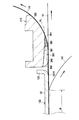
以上説明した本実施形態によれば、図5に示すように、定着ベルト110と傾斜面360との間にグリス190が溜まったとしても、定着ベルト110の回転により、グリス190を傾斜面360に沿わせて定着ベルト110の内周面、さらに言えば、定着ベルト110と下流ガイド320との間に移動させることができる。つまり、本実施形態によれば、傾斜面360によって、定着ベルト110の内周面へのグリス190の供給能力を向上させることができる。これにより、定着ベルト110とニップ板130などとの間に十分なグリス190を介在させることができるので、定着ベルト110の摺動抵抗の増大を抑制することができる。
According to the present embodiment described above, as shown in FIG. 5, even if the
なお、本発明は前記実施形態に限定されることなく、以下に例示するように様々な形態で利用できる。以下の説明においては、前記実施形態と略同様の構造となる部材には同一の符号を付し、その説明は省略する。 In addition, this invention is not limited to the said embodiment, It can utilize with various forms so that it may illustrate below. In the following description, the same reference numerals are given to members having substantially the same structure as in the above embodiment, and the description thereof is omitted.
前記実施形態では、傾斜面360が平面状であったが、本発明はこれに限定されるものではない。例えば、図6に示すように、傾斜面361は、定着ベルト110の幅方向から見た断面形状が定着ベルト110に近づく方向に凸となる、凸曲面状であってもよい。また、図7に示すように、傾斜面362は、定着ベルト110の幅方向から見た断面形状が定着ベルト110から離れる方向に凹となる、凹曲面状であってもよい。
In the said embodiment, although the
前記実施形態では、傾斜面360が、定着ベルト110の回転方向におけるギャップ形成部350の全範囲にわたって設けられていたが、本発明はこれに限定されるものではない。例えば、図8に示すように、傾斜面363は、定着ベルト110の回転方向におけるギャップ形成部350の下流端351から、定着ベルト110の回転方向上流側に向けて所定の範囲W1の部分だけに設けられていてもよい。具体的に、図8の形態では、傾斜面363は、一例として、定着ベルト110の回転方向におけるギャップ形成部350の下流側の略半分だけに設けられている。なお、このような構成において、傾斜面363は、図8に示したように平面状であってもよいし、図6の形態や図7の形態と同様の曲面状であってもよい。
In the embodiment, the
前記実施形態では、傾斜面360は、その全体が、平面PLに対する最大傾斜角θが90°未満となるように形成されていたが、本発明はこれに限定されるものではない。例えば、図9に示すように、傾斜面364、詳しくは、ギャップ形成部350の底面は、ギャップ形成部350の下流端351から、少なくとも定着ベルト110との間でグリス190が溜まる範囲W2では、平面PLに対する最大傾斜角θが90°未満であり、範囲W2よりも上流側の範囲では、平面PLに対する最大傾斜角が90°以上となる部分を有するような構成であってもよい。具体的に、図9の形態では、ギャップ形成部350の底面は、グリス190が溜まる範囲W2よりも上流側であって、所定の範囲W1よりも上流側の部分に、平面PLに対して90°以上の角度をなす部分(段差部364B)を有している。このような段差部364Bを有していても、段差部364Bの付近にはグリス190が溜まらないので、グリス190が潤滑に利用されなくなるという問題は生じない。
In the above embodiment, the entire
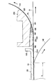
グリス190が溜まる範囲W2は、定着ベルト110の回転方向におけるギャップ形成部350の下流端351から2mm程度となることが多いので、本発明は別の言い方をすると、傾斜面364(ギャップ形成部350の底面)は、ギャップ形成部350の下流端351から2mmの範囲では、平面PLに対する最大傾斜角θが90°未満であるということができる。なお、グリス190が溜まる範囲W2は、定着ベルト110の内周面に配置されたグリス190の量などによって変わるので、2mmよりも狭くなる場合もあり得る。
The range W2 in which the
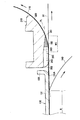
また、図10に示すように、傾斜面365は、グリス190が溜まる範囲W2の下流側の部分に設けられていてもよい。図10に示す形態において、傾斜面365は、定着ベルト110の幅方向から見た断面形状が定着ベルト110に近づく方向に凸となる、凸曲面状に形成されている。さらに説明すると、傾斜面365は、定着ベルト110の幅方向から見た断面形状が略円弧状をなしている。
Moreover, as shown in FIG. 10, the
前記実施形態では、ガイド部材として、その一部である下流ガイド320やギャップ形成部350が定着ベルト110の回転方向におけるニップNの下流側に配置された第1カバー部材210を例示したが、本発明はこれに限定されるものではない。例えば、ガイド部材は、その全体が定着ベルトの回転方向におけるニップの下流側に配置されるような構成であってもよい。
In the above-described embodiment, the
前記実施形態では、バックアップ部材として加圧ローラ140を例示したが、本発明はこれに限定されず、例えば、ベルト状の加圧部材などであってもよい。
In the embodiment, the
前記実施形態では、ニップ部材の一例としてニップ板130を例示したが、本発明はこれに限定されず、板状でない厚めの部材であってもよい。
In the embodiment, the
前記実施形態では、カラーレーザプリンタ1に本発明を適用したが、本発明はこれに限定されず、その他の画像形成装置、例えば複写機や複合機などに本発明を適用してもよい。
In the above embodiment, the present invention is applied to the
なお、定着ベルトは、ポリイミドを主成分とする樹脂フィルムであってもよい。定着ベルトは、この場合、表層にPTFEなどのフッ素樹脂により被覆されている。 Note that the fixing belt may be a resin film containing polyimide as a main component. In this case, the fixing belt is covered with a fluororesin such as PTFE on the surface layer.
100 定着装置
110 定着ベルト
130 ニップ板
131 板状部
140 加圧ローラ
190 グリス
210 第1カバー部材
320 下流ガイド
350 ギャップ形成部
351 下流端
360 傾斜面
G ギャップ
N ニップ
DESCRIPTION OF
Claims (9)
前記エンドレスベルトの内周面に配置された潤滑剤と、
前記エンドレスベルトの内周面に摺接する摺接部を有するニップ部材と、
前記ニップ部材との間で前記エンドレスベルトを挟み、前記エンドレスベルトとの間にニップを形成するバックアップ部材と、
前記エンドレスベルトの回転方向における前記ニップの下流側に配置され、前記ニップ部材と前記バックアップ部材との間から出た前記エンドレスベルトをガイドするガイド部材と、を備え、
前記ガイド部材は、
前記エンドレスベルトの内周面に摺接して前記エンドレスベルトをガイドするガイド部と、
前記回転方向における前記ニップと前記ガイド部との間に設けられ、前記エンドレスベルトの幅方向における前記エンドレスベルトの両端部の内周面に摺接して前記エンドレスベルトを前記ガイド部に向けてガイドする一対の端部ガイドと、
前記エンドレスベルトの幅方向における前記一対の端部ガイドの間に形成され、前記エンドレスベルトとの間にギャップを形成するギャップ形成部と、を有し、
前記ギャップ形成部は、当該ギャップ形成部の前記回転方向における下流端から少なくとも所定の範囲の部分に前記ガイド部につながる傾斜面を有し、
前記傾斜面は、前記エンドレスベルトとの間で前記潤滑剤が溜まる範囲では、前記摺接部の前記回転方向における下流端と前記ガイド部とに接する平面に対する最大傾斜角が90°未満であり、
前記端部ガイドの、前記エンドレスベルトをガイドするガイド面は、前記平面に対して前記ガイド部とは反対側に位置していることを特徴とする定着装置。 Endless belt,
A lubricant disposed on the inner peripheral surface of the endless belt;
A nip member having a sliding contact portion in sliding contact with the inner peripheral surface of the endless belt;
A backup member that sandwiches the endless belt with the nip member and forms a nip with the endless belt;
A guide member that is disposed downstream of the nip in the rotational direction of the endless belt and guides the endless belt that has come out between the nip member and the backup member,
The guide member is
A guide portion for slidingly contacting the inner peripheral surface of the endless belt to guide the endless belt;
Provided between the nip in the rotation direction and the guide portion, and slidably contact inner peripheral surfaces of both end portions of the endless belt in the width direction of the endless belt to guide the endless belt toward the guide portion. A pair of end guides;
A gap forming portion formed between the pair of end guides in the width direction of the endless belt and forming a gap with the endless belt,
The gap forming portion has at least inclined surface leading to front Symbol guide portion in a portion of the predetermined range from the downstream end in the rotating direction of the gap forming portions,
The inclined surface is in a range where the lubricant is accumulated between the endless belt, Ri maximum tilt angle of 90 ° below der respect to a plane in contact with the downstream end of the guide portion in the rotation direction of the sliding contact portion ,
The fixing device according to claim 1, wherein a guide surface of the end guide for guiding the endless belt is located on a side opposite to the guide portion with respect to the plane .
前記エンドレスベルトの内周面に配置された潤滑剤と、
前記エンドレスベルトの内周面に摺接する摺接部を有するニップ部材と、
前記ニップ部材との間で前記エンドレスベルトを挟み、前記エンドレスベルトとの間にニップを形成するバックアップ部材と、
前記エンドレスベルトの回転方向における前記ニップの下流側に配置され、前記ニップ部材と前記バックアップ部材との間から出た前記エンドレスベルトをガイドするガイド部材と、を備え、
前記ガイド部材は、
前記エンドレスベルトの内周面に摺接して前記エンドレスベルトをガイドするガイド部と、
前記回転方向における前記ニップと前記ガイド部との間に設けられ、前記エンドレスベルトの幅方向における前記エンドレスベルトの両端部の内周面に摺接して前記エンドレスベルトを前記ガイド部に向けてガイドする一対の端部ガイドと、
前記エンドレスベルトの幅方向における前記一対の端部ガイドの間に形成され、前記エンドレスベルトとの間にギャップを形成するギャップ形成部と、を有し、
前記ギャップ形成部は、当該ギャップ形成部の前記回転方向における下流端から少なくとも所定の範囲の部分に前記ガイド部につながる傾斜面を有し、
前記傾斜面は、前記ギャップ形成部の前記回転方向における下流端から2mmの範囲では、前記摺接部の前記回転方向における下流端と前記ガイド部とに接する平面に対する最大傾斜角が90°未満であり、
前記端部ガイドの、前記エンドレスベルトをガイドするガイド面は、前記平面に対して前記ガイド部とは反対側に位置していることを特徴とする定着装置。 Endless belt,
A lubricant disposed on the inner peripheral surface of the endless belt;
A nip member having a sliding contact portion in sliding contact with the inner peripheral surface of the endless belt;
A backup member that sandwiches the endless belt with the nip member and forms a nip with the endless belt;
A guide member that is disposed on the downstream side of the nip in the rotation direction of the endless belt and guides the endless belt that has come out between the nip member and the backup member,
The guide member is
A guide portion that guides the endless belt in sliding contact with an inner peripheral surface of the endless belt;
Provided between the nip in the rotation direction and the guide portion, and slidably contact inner peripheral surfaces of both end portions of the endless belt in the width direction of the endless belt to guide the endless belt toward the guide portion. A pair of end guides;
A gap forming portion that is formed between the pair of end guides in the width direction of the endless belt and that forms a gap with the endless belt,
The gap forming portion has at least inclined surface leading to front Symbol guide portion in a portion of the predetermined range from the downstream end in the rotating direction of the gap forming portions,
In the range of 2 mm from the downstream end in the rotation direction of the gap forming portion, the inclined surface has a maximum inclination angle of less than 90 ° with respect to the plane contacting the downstream end in the rotation direction of the sliding contact portion and the guide portion. Oh it is,
The fixing device , wherein a guide surface of the end guide for guiding the endless belt is located on a side opposite to the guide portion with respect to the plane .
前記ギャップ形成部は、前記エンドレスベルトの幅方向において断続的に複数形成されており、A plurality of the gap forming portions are intermittently formed in the width direction of the endless belt,
前記被検知部は、前記エンドレスベルトの幅方向において隣り合う前記ギャップ形成部の間に配置されていることを特徴とする請求項1から請求項8のいずれか1項に記載の定着装置。The fixing device according to claim 1, wherein the detected portion is disposed between the gap forming portions adjacent in the width direction of the endless belt.
Priority Applications (1)
| Application Number | Priority Date | Filing Date | Title |
|---|---|---|---|
| US14/864,978 US9442441B2 (en) | 2014-09-29 | 2015-09-25 | Fixing device |
Applications Claiming Priority (2)
| Application Number | Priority Date | Filing Date | Title |
|---|---|---|---|
| JP2014198794 | 2014-09-29 | ||
| JP2014198794 | 2014-09-29 |
Publications (2)
| Publication Number | Publication Date |
|---|---|
| JP2016071333A JP2016071333A (en) | 2016-05-09 |
| JP6593006B2 true JP6593006B2 (en) | 2019-10-23 |
Family
ID=55864669
Family Applications (1)
| Application Number | Title | Priority Date | Filing Date |
|---|---|---|---|
| JP2015146420A Active JP6593006B2 (en) | 2014-09-29 | 2015-07-24 | Fixing device |
Country Status (1)
| Country | Link |
|---|---|
| JP (1) | JP6593006B2 (en) |
Families Citing this family (1)
| Publication number | Priority date | Publication date | Assignee | Title |
|---|---|---|---|---|
| JP6792814B2 (en) * | 2016-07-21 | 2020-12-02 | 株式会社リコー | Fixing device and image forming device |
Family Cites Families (6)
| Publication number | Priority date | Publication date | Assignee | Title |
|---|---|---|---|---|
| JP2000039787A (en) * | 1998-07-22 | 2000-02-08 | Canon Inc | Heating device, heat fixing device, and image forming device |
| JP2006310017A (en) * | 2005-04-27 | 2006-11-09 | Canon Inc | Heating device |
| JP4681966B2 (en) * | 2005-07-22 | 2011-05-11 | キヤノン株式会社 | Image fixing device |
| JP4962057B2 (en) * | 2007-03-09 | 2012-06-27 | 富士ゼロックス株式会社 | Fixing apparatus and image forming apparatus |
| US7848672B2 (en) * | 2008-10-02 | 2010-12-07 | Xerox Corporation | Fusers including heater for pre-heating fuser belt, printing apparatuses and methods of fusing toner on media with pre-heating of fuser belt |
| JP5895418B2 (en) * | 2011-09-20 | 2016-03-30 | ブラザー工業株式会社 | Fixing device |
-
2015
- 2015-07-24 JP JP2015146420A patent/JP6593006B2/en active Active
Also Published As
| Publication number | Publication date |
|---|---|
| JP2016071333A (en) | 2016-05-09 |
Similar Documents
| Publication | Publication Date | Title |
|---|---|---|
| JP5754230B2 (en) | Fixing device | |
| CN205485290U (en) | Fixing device | |
| JP2013250423A (en) | Fixing device and manufacturing method of the same | |
| JP6164017B2 (en) | Fixing device | |
| JP6417693B2 (en) | Fixing apparatus and image forming apparatus | |
| US9423735B2 (en) | Fixing device | |
| JP5273138B2 (en) | Fixing device | |
| JP6197328B2 (en) | Fixing device | |
| JP6361234B2 (en) | Fixing device | |
| JP5953720B2 (en) | Fixing device | |
| JP6349884B2 (en) | Fixing device | |
| JP5935305B2 (en) | Fixing device | |
| US9069309B2 (en) | Fixing device | |
| JP2016166921A (en) | Fixing device | |
| JP6593006B2 (en) | Fixing device | |
| US9442441B2 (en) | Fixing device | |
| JP2016161679A (en) | Fixing device | |
| JP2015197485A (en) | Fixing device | |
| JP6684476B2 (en) | Fixing device | |
| JP2015194564A (en) | fixing device | |
| US8831496B2 (en) | Fuser unit | |
| JP6318779B2 (en) | Fixing device | |
| JP6848523B2 (en) | Fixing device | |
| JP2017107097A (en) | Fixing device | |
| JP6500510B2 (en) | Fixing device |
Legal Events
| Date | Code | Title | Description |
|---|---|---|---|
| A621 | Written request for application examination |
Free format text: JAPANESE INTERMEDIATE CODE: A621 Effective date: 20180628 |
|
| A977 | Report on retrieval |
Free format text: JAPANESE INTERMEDIATE CODE: A971007 Effective date: 20190415 |
|
| A131 | Notification of reasons for refusal |
Free format text: JAPANESE INTERMEDIATE CODE: A131 Effective date: 20190423 |
|
| RD03 | Notification of appointment of power of attorney |
Free format text: JAPANESE INTERMEDIATE CODE: A7423 Effective date: 20190522 |
|
| A521 | Written amendment |
Free format text: JAPANESE INTERMEDIATE CODE: A821 Effective date: 20190522 |
|
| A601 | Written request for extension of time |
Free format text: JAPANESE INTERMEDIATE CODE: A601 Effective date: 20190619 |
|
| A521 | Written amendment |
Free format text: JAPANESE INTERMEDIATE CODE: A523 Effective date: 20190809 |
|
| TRDD | Decision of grant or rejection written | ||
| A01 | Written decision to grant a patent or to grant a registration (utility model) |
Free format text: JAPANESE INTERMEDIATE CODE: A01 Effective date: 20190827 |
|
| A61 | First payment of annual fees (during grant procedure) |
Free format text: JAPANESE INTERMEDIATE CODE: A61 Effective date: 20190909 |
|
| R150 | Certificate of patent or registration of utility model |
Ref document number: 6593006 Country of ref document: JP Free format text: JAPANESE INTERMEDIATE CODE: R150 |