JP6620002B2 - Fluid concentration measuring device and bubble detecting device - Google Patents
Fluid concentration measuring device and bubble detecting device Download PDFInfo
- Publication number
- JP6620002B2 JP6620002B2 JP2015242319A JP2015242319A JP6620002B2 JP 6620002 B2 JP6620002 B2 JP 6620002B2 JP 2015242319 A JP2015242319 A JP 2015242319A JP 2015242319 A JP2015242319 A JP 2015242319A JP 6620002 B2 JP6620002 B2 JP 6620002B2
- Authority
- JP
- Japan
- Prior art keywords
- light
- groove
- light receiving
- lid
- concentration measuring
- Prior art date
- Legal status (The legal status is an assumption and is not a legal conclusion. Google has not performed a legal analysis and makes no representation as to the accuracy of the status listed.)
- Active
Links
Images




Landscapes
- Investigating Or Analyzing Materials By The Use Of Ultrasonic Waves (AREA)
- Optical Measuring Cells (AREA)
- Investigating Or Analysing Materials By Optical Means (AREA)
Description
この発明は、光透過性でかつ変形可能な管路内を流れる流体の濃度を測定する流体濃度測定装置および変形可能な管路内を流れる流体中の気泡を検出する気泡検出装置に関する。 The present invention relates to a fluid concentration measuring device that measures the concentration of a fluid that flows through a deformable conduit that is light transmissive, and a bubble detector that detects bubbles in the fluid flowing through a deformable conduit.
従来の流体濃度測定装置としては、例えば特許文献1記載のものが知られており、ここにおける測定方法および測定装置は、半導体ウエハを洗浄処理する流体としての処理液の濃度を測定するもので、処理液供給配管の途中に測定体を複数設け、各測定体内に、処理液中を通過する光の光路長さを異ならせた光透過部を設け、処理液の性質に応じた光路長さの光透過部に光源からの光を供給し、その光透過部において処理液中を透過した光を光検出器で受光してその光の強度を調べ、その光の強度からランベルト−ベールの法則に基づいて処理液の濃度を求めている。
As a conventional fluid concentration measuring device, for example, the one described in
しかしながら上記従来の装置を、樹脂チューブやガラス管等の光透過性の管路内を流れる血液や薬液等の流体の濃度測定に適用しようとすると、光透過性の管路を横切る光路に光を通過させる必要があるが、光路長さとなる管路の内径も管路の壁厚さも実測が困難であり、特に管路が変形可能な樹脂チューブの場合はその変形によって内径が変化する可能性があり、それゆえこのような場合の血液や薬液等の濃度の測定は極めて困難で、従来は実質上その測定ができなかった。 However, if the conventional device is applied to measure the concentration of a fluid such as blood or a chemical solution flowing in a light-transmitting conduit such as a resin tube or a glass tube, light is transmitted to the optical path crossing the light-transmitting conduit. Although it is necessary to pass through, it is difficult to actually measure the inner diameter of the pipe and the wall thickness of the pipe as the optical path length, and in particular, in the case of a resin tube that can deform the pipe, the inner diameter may change due to the deformation. Therefore, it is extremely difficult to measure the concentration of blood, chemicals, etc. in such a case, and it has been practically impossible to measure the concentration.
このため本願発明者は、特許文献2の図1(a)に示されるように、ケースの上部に左右方向に延在する溝を備えるとともに、樹脂チューブを間に挟んで直径方向に圧縮変形させるようにケースの溝の側壁部に向かい合わせに固定された発光ユニットと受光ユニットとの対である発光受光ユニットを相互に光路距離が異なるよう二対備え、それぞれの光路距離における受光箇所での光の強度からランベルト−ベールの法則に基づき、樹脂チューブ内の濃度を求める流体濃度測定装置を提案している。 For this reason, as shown in FIG. 1A of Patent Document 2, the inventor of the present application includes a groove extending in the left-right direction in the upper part of the case, and compressively deforms in the diameter direction with a resin tube interposed therebetween. In this way, two pairs of light emitting / receiving units, which are a pair of a light emitting unit and a light receiving unit fixed so as to face the side wall of the groove of the case, are provided so that the optical path distances are different from each other, and light at the light receiving point at each optical path distance Has proposed a fluid concentration measuring device for obtaining the concentration in a resin tube based on the Lambert-Beer law from the strength of the above.
そしてこの流体濃度測定装置では、正確な濃度測定のために発光ユニットおよび受光ユニットを樹脂チューブに対して確実に密着させることが肝要であり、そのために発光ユニットおよび受光ユニット間であらかじめ狭窄部を形成してこの狭窄部に樹脂チューブを押し込むようにして装着するようにしているが、このとき樹脂チューブに歪みや捩れが発生し、これが樹脂チューブを経時的に変形させる結果、測定結果にばらつきが生じる虞がある。さらに、樹脂チューブをこれよりも幅の狭い溝内に装着する必要があるため、装着に手間がかかり未だ改良の余地があることが判明した。また測定を終え、樹脂チューブを装置から取り外す場合も同様であり、樹脂チューブが溝の狭窄部に引っかかり、無理に引っ張れば樹脂チューブを伸ばしてしまうおそれがあるため注意を要する作業となる。また、このような問題は、変形可能な管路の表面に超音波を発信し、液体と気泡ではその透過率が異なることに基づき透過率の差を検出して気泡の有無を検出する装置においても同様に生じ得る。 In this fluid concentration measuring device, it is important to ensure that the light-emitting unit and the light-receiving unit are in close contact with the resin tube for accurate concentration measurement. For this reason, a constriction is formed in advance between the light-emitting unit and the light-receiving unit. Then, the resin tube is pushed into the constricted portion and attached, but at this time, the resin tube is distorted and twisted, which deforms the resin tube over time, resulting in variations in measurement results. There is a fear. Furthermore, since it is necessary to install the resin tube in a narrower groove than this, it has been found that there is still room for improvement because it takes time for installation. The same applies to the case where the measurement is finished and the resin tube is removed from the apparatus, and the resin tube is caught in the constricted portion of the groove, and if it is forcibly pulled, the resin tube may be stretched, which requires care. In addition, such a problem occurs in an apparatus that detects the presence or absence of bubbles by transmitting ultrasonic waves to the surface of a deformable pipe and detecting the difference in transmittance based on the difference in transmittance between liquid and bubbles. Can occur as well.
この発明は上記課題を有利に解決するものであり、この発明の流体濃度測定装置は、光透過性でかつ変形可能な管路内を流れる流体の濃度を測定する流体濃度測定装置であって、
前記管路が装着される上向きに開口する溝が形成された筐体と、
前記溝の一方の側面側に配置され、前記管路の表面上に光を供給する発光部と、
前記溝の他方の側面側に前記発光部に対向配置され、前記管路を透過した光を受光する受光部と、
ヒンジを介して前記筐体に開閉可能に連結され、閉姿勢にて前記溝の上部開口を閉止する蓋体と、
前記筐体に昇降可能に保持され、前記蓋体の閉動作に伴い該蓋体によって押し下げられる押下部材と、
前記発光部または前記受光部を保持するとともに前記押下部材の押し下げに連動して作動することで対向する前記発光部と前記受光部とを互いに接近させる作動部材と、
前記作動部材の作動を規制して前記発光部および前記受光部間を所定間隔に保持するストッパ部材と、を備えることを特徴とするものである。
The present invention advantageously solves the above problems, and the fluid concentration measuring device of the present invention is a fluid concentration measuring device for measuring the concentration of a fluid flowing in a light-transmissive and deformable pipe,
A housing formed with an upwardly opening groove to which the conduit is mounted;
A light-emitting unit disposed on one side of the groove and supplying light onto the surface of the conduit;
A light receiving portion that is disposed opposite to the light emitting portion on the other side surface side of the groove and receives light transmitted through the conduit;
A lid that is openably and closably connected to the housing via a hinge and closes the upper opening of the groove in a closed position;
A pressing member that is held in the casing so as to be movable up and down, and is pushed down by the lid in accordance with the closing operation of the lid;
An operation member that holds the light emitting unit or the light receiving unit and moves the light emitting unit and the light receiving unit facing each other by operating in conjunction with the pressing of the pressing member;
And a stopper member that regulates the operation of the operation member and holds the light emitting unit and the light receiving unit at a predetermined interval.
また、この発明の気泡検出装置は、変形可能な管路内を流れる流体中の気泡の有無を検出する気泡検出装置であって、
前記管路が装着される上向きに開口する溝が形成された筐体と、
前記溝の一方の側面側に配置され、前記管路の表面上に超音波を発信する発信部と、
前記溝の他方の側面側に前記発信部に対向配置され、前記管路を透過した超音波を受信する受信部と、
ヒンジを介して前記筐体に開閉可能に連結され、閉姿勢にて前記溝の上部開口を閉止する蓋体と、
前記筐体に昇降可能に保持され、前記蓋体の閉動作に伴い該蓋体によって押し下げられる押下部材と、
前記発信部または前記受信部を保持するとともに前記押下部材の押し下げに連動して作動することで対向する前記発信部と前記受信部とを互いに接近させる作動部材と、
前記作動部材の作動を規制して前記発信部および前記受信部間を所定間隔に保持するストッパ部材と、を備えることを特徴とするものである。
The bubble detection device of the present invention is a bubble detection device that detects the presence or absence of bubbles in a fluid flowing in a deformable pipe,
A housing formed with an upwardly opening groove to which the conduit is mounted;
A transmitter that is disposed on one side of the groove and transmits ultrasonic waves on the surface of the pipe;
A receiving unit that is disposed opposite to the transmitting unit on the other side surface of the groove and receives the ultrasonic wave transmitted through the conduit;
A lid that is openably and closably connected to the housing via a hinge and closes the upper opening of the groove in a closed position;
A pressing member that is held in the casing so as to be movable up and down, and is pushed down by the lid in accordance with the closing operation of the lid;
An operating member that holds the transmitting unit or the receiving unit and moves the opposing transmitting unit and the receiving unit closer to each other by operating in conjunction with the pressing of the pressing member;
And a stopper member that regulates the operation of the operating member and holds the transmitter and the receiver at a predetermined interval.
かかるこの発明の流体濃度測定装置にあっては、光透過性でかつ変形可能な管路を筐体に形成された溝内に装着する際、蓋体が開放された状態では発光部または受光部を保持する作動部材は、発光部および受光部間の距離を離間させる方向に移動可能である。そして筐体の溝内に管路を装着し蓋体を閉めると、蓋体の閉動作に伴う押下部材の押し下げに連動して作動部材が発光部と受光部とを接近させ、発光部および受光部は共に管路に圧接される。このとき、作動部材の作動はストッパ部材によって規制され、発光部および受光部間は所定間隔に保持される。 In such a fluid concentration measuring device of the present invention, when the light-transmitting and deformable conduit is mounted in the groove formed in the housing, the light emitting unit or the light receiving unit is in a state where the lid is opened. The actuating member that holds can be moved in a direction that separates the distance between the light emitting unit and the light receiving unit. When the conduit is installed in the groove of the housing and the lid is closed, the actuating member brings the light emitting portion and the light receiving portion closer together in conjunction with the pressing of the pressing member accompanying the closing operation of the lid. Both parts are pressed against the pipeline. At this time, the operation of the operating member is regulated by the stopper member, and the light emitting unit and the light receiving unit are held at a predetermined interval.
従って、この発明の流体濃度測定装置によれば、蓋体が開放された状態では、測定時に狭窄部となる箇所の溝幅を一時的に広げることができて管路を無理なく溝内に装着または溝から取り外すことができる。また、測定時には蓋体の閉動作に連動して作動部材が、発光部と受光部とを接近させるため発光部および受光部を共に管路に確実に圧接させることができるとともに、ストッパ部材による作動部材の作動の規制により発光部および受光部間に常に一定の光路距離がもたらされ、かつ、従来のような管路に生じる歪みや捩れを有効に防止して経時的に発生する管路の変形を効果的に阻止することができるため、正確な測定を行うことができる。 Therefore, according to the fluid concentration measuring device of the present invention, when the lid is opened, the groove width of the portion that becomes the narrowed portion at the time of measurement can be temporarily widened so that the pipe line can be easily installed in the groove. Or it can be removed from the groove. In addition, when the measurement is performed, the actuating member interlocks with the closing operation of the lid to bring the light-emitting part and the light-receiving part closer together, so that both the light-emitting part and the light-receiving part can be reliably brought into pressure contact with the pipe line and actuated by the stopper member. By restricting the operation of the member, a constant optical path distance is always provided between the light emitting unit and the light receiving unit, and distortion and twisting that occur in the conventional pipeline are effectively prevented, and the pipeline generated over time is prevented. Since deformation can be effectively prevented, accurate measurement can be performed.
なお、この発明の流体濃度測定装置においては、前記溝および前記作動部材を2組備え、前記押下部材の押し下げに連動して2つの作動部材を同時に作動させる伝達部材を備えていてもよく、このようにすれば、例えば血液透析療法における血液透析前後の濃度測定が一台の濃度測定装置により可能となる。 The fluid concentration measuring device according to the present invention may include two sets of the groove and the actuating member, and a transmission member that simultaneously operates the two actuating members in conjunction with the depression of the push-down member. By doing so, for example, concentration measurement before and after hemodialysis in hemodialysis therapy can be performed with a single concentration measuring device.
また、この発明の流体濃度測定装置においては、前記押圧部材と前記作動部材との間に介装された弾性部材を備えていてもよく、これによれば、押圧部材や作動部材に多少の寸法誤差があってもこの弾性部材により当該誤差を吸収することが可能であるとともに、外径の異なる管路を用いる場合においても、発光部および受光部を管路に確実に圧接させることができる。 Moreover, in the fluid concentration measuring apparatus of this invention, you may provide the elastic member interposed between the said press member and the said operation member, and according to this, a some dimension is provided in a press member or an operation member. Even if there is an error, the elastic member can absorb the error, and the light emitting portion and the light receiving portion can be reliably brought into pressure contact with the conduit even when using conduits having different outer diameters.
さらに、この発明の流体濃度測定装置においては、前記発光部と前記受光部とを互いに離間させる方向に前記作動部材を直接的または間接的に付勢する付勢部材を備えていてもよく、これによれば、蓋体が開放された状態では溝の狭窄部は常時拡げられているため、溝への管路の着脱をより一層負荷なく行うことが可能である。 Furthermore, the fluid concentration measuring apparatus of the present invention may further include a biasing member that biases the operating member directly or indirectly in a direction in which the light emitting unit and the light receiving unit are separated from each other. According to the above, since the narrowed portion of the groove is always expanded in the state in which the lid is opened, it is possible to attach and detach the conduit to and from the groove without any further load.
また、この発明の気泡検出装置によれば、蓋体が開放された状態では、測定時に狭窄部となる箇所の溝幅を一時的に広げることができて管路を無理なく溝内に装着または溝から取り外すことができる。また、測定時には蓋体の閉動作に連動して作動部材が作動し、発信部と受信部とが接近するため発信部および受信部を共に管路に確実に圧接させることができるとともに、ストッパ部材による作動部材の作動の規制により発信部および受信部間に常に一定の光路距離がもたらされ、管路内の流体中の気泡の有無を正確に検出することができる。 Further, according to the bubble detection device of the present invention, in the state where the lid is opened, the groove width of the portion that becomes the narrowed portion at the time of measurement can be temporarily widened so that the pipe line can be mounted in the groove without difficulty. Can be removed from the groove. In addition, when the measurement is performed, the operating member is operated in conjunction with the closing operation of the lid, and the transmitting unit and the receiving unit are brought close to each other, so that both the transmitting unit and the receiving unit can be reliably brought into pressure contact with the pipeline, and the stopper member Due to the restriction of the operation of the operation member by the above, a constant optical path distance is always provided between the transmission part and the reception part, and the presence or absence of bubbles in the fluid in the pipe line can be accurately detected.
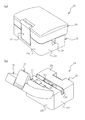
以下、この発明の実施の形態について図面に基づき詳細に説明する。図1にこの発明の一実施形態の流体濃度測定装置10を示す。この図に示すように、この流体濃度測定装置10は、装置10の主要部を収容する筐体12と、該筐体12にヒンジ14を介して開閉自在に連結された蓋体16と、蓋体16の前面中央(ヒンジ14の反対側)に設けられ、筐体12に対する蓋体16の閉塞姿勢を保持するフックの如き緊締具18を備える。
Hereinafter, embodiments of the present invention will be described in detail with reference to the drawings. FIG. 1 shows a fluid
筐体12は、互いに対向する前壁12aおよび後壁12bと、互いに対向配置され前壁12aおよび後壁12b間をつなぐ右側壁12cおよび左側壁12dと、これら壁12a〜12dの上端をつなぐ上壁12eとを有する。
The
筐体12の上壁12eの前後方向略中央位置には、光透過性でかつ変形可能な管路としての樹脂製チューブ(樹脂チューブ)が装着される上向きに開口する溝20が形成されており、この溝20は筐体12の左右側壁12c,12d間に直線状に延びる。溝20の幅は長手方向の両端部において小さく、両端部間の中間部において僅かに拡大されている。両端部における溝幅は、溝20に装着される樹脂チューブの外径と同じか若しくはそれよりも僅かに大であることが好ましい。
A
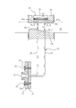
図1(b)および図2に示すように、流体濃度測定装置10は、溝20の幅方向で向かい合わせに配置されて、それぞれ溝20の側壁部の一部をなす発光部22および受光部24を備えている。
As shown in FIG. 1B and FIG. 2, the fluid
発光部22および受光部24の詳細を図3に模式的に示す。発光部22は、光源としての発光ダイオード(LED)もしくはレーザーダイオード等の、電気を供給されて発光する発光素子25を有し、その発光素子25からの光を樹脂チューブの表面上に位置する光供給箇所Sから樹脂チューブ内に供給する。図示例では、光供給箇所Sは樹脂チューブの長手方向(延在方向)に離間して2箇所に設けられ、1つの発光素子25から各光供給箇所Sまで2本の光ファイバー26,27を介して光が伝播されるよう構成されている。各光ファイバー26,27の終端には上記光供給箇所Sとなるボールレンズ29,30がそれぞれ設けられ、光ファイバー26,27のコア径よりも拡大されたコリメート光が出射される。また、図中、符号31は光ファイバー固定板、符号32は発光素子保持板であり、両部材31,32はねじ33を介して相互に固定される。発光素子保持板32の、ねじ33の挿入孔32aは光ファイバー26,27の並置方向に長い長孔として形成されている。これにより発光素子保持板32は光ファイバー固定板31に対して上記並置方向に位置調整可能であり、2本の光ファイバー26,27に対する光軸を合わせて両光ファイバー26,27間で光強度を互いに同じにすることができる。
Details of the
受光部24は、フォトダイオードやフォトトランジスタ等の、光を受光して電気を発生させる受光素子を有して、発光部22から供給され樹脂チューブ内を透過してきた光を受光してその光の強度に応じた電気信号を出力する。図示例では、受光素子として、上記光供給箇所Sに対し樹脂チューブの直径方向の反対側に位置するとともに樹脂チューブの延在方向に互いに等間隔に直線状に連続して並んだ多数の受光素子35aを有するラインセンサ35を用いている。ラインセンサ35は受光素子35aの信号を経時的に並べて順次に出力する多数の例えば電荷結合素子(CCD)を有していてよい。ラインセンサ35の多数の受光素子35aは、あらかじめ互いに同一感度に調整されている。樹脂チューブ内を透過してきた光は受光箇所Rとなるボールレンズ36,37によりコリメート(集光)され、ラインセンサ35がその光を受光する。なお、この例において、2つの光供給箇所Sから対向する受光箇所Rまでの距離(光路長)L,lは相互に異なるよう設定されているが、2つの光路長L,lは互いに同じに設定してもよい。また、発光部22および受光部24は、例えば、動脈血の酸素化ヘモグロビンと静脈血の脱酸素化ヘモグロビンとの両方の吸光率がほぼ等しい光として590nm付近の波長の光を発光および受光するものであってよい。
The
次いで、発光部22および受光部24の保持構造について説明すると、図4(a)に示すように、流体濃度測定装置10は発光部22を保持する、作動部材としての揺動部材38を備えている。揺動部材38は、前後方向に沿う縦断面(図4(a))でみて2つの脚部38a,38bがその基端部において一体につながる略L字形をなし、その角部近傍において、軸部39を介して樹脂チューブTBの延在方向に沿う軸線周りに揺動可能に筐体12に支持されている。略水平方向に延びる一方の脚部38aの末端部には後述のコイルスプリングを受ける凹部41,42が上下両面に形成されている。略鉛直に延びる他方の脚部38b上部には発光部22の光ファイバー26,27の末端部が挿通され支持されている。この脚部38b上部の、光ファイバー26,27の末端に設けられたボールレンズ29,30を露出させる壁部は溝20の側壁部の一部を構成することとなる。この壁部は溝20の長手方向に沿って溝幅を変化させる傾斜面として形成されていて(図3参照)、発光部22における上記2つのボールレンズ29,30はこの傾斜面内に配置されている。これにより、発光部22のボールレンズ29,30と受光部24のボールレンズ36,37との間には2つの異なる長さの光路L,lが形成される。また、略鉛直方向に延びる脚部38bの下部(下面)には上述の光ファイバー固定板31および発光素子保持板32が取り付けられ、これらの光ファイバー固定板31および発光素子保持板32は揺動部材38と一緒に軸部39周りに揺動する。
Next, the holding structure of the
他方、受光部24におけるラインセンサ35は断面略コ字状のセンサ保持部材44内に保持されている。センサ保持部材44の垂壁44aは溝20の側壁部の一部を構成する。図3に示すように、この垂壁44aには樹脂チューブ内を透過してきた光をラインセンサに向けて通過させる2つの通路(貫通孔)44a1,44a2が形成され(図3参照)、各通路44a1,44a2の始端には上記ボールレンズ36,37が固定されている。
On the other hand, the
揺動部材38は、図4(a),(b)に示すように、溝20とヒンジ14との間で筐体12の上壁12eに昇降可能に保持されかつその頭部が筐体12の上壁12eから突出して蓋体16によって押下される押下部材46によって揺動される。押下部材46と揺動部材38の間には、揺動部材38の略水平に延びる脚部38a上面に設けられた上記凹部41内に着座する、弾性部材としてのコイルスプリング47が介装されており、押下部材46からの押下力はこのコイルスプリング47を介して揺動部材38に伝達され、揺動部材38は軸部39を中心に図4(a)において時計回りに揺動する。
As shown in FIGS. 4A and 4B, the
揺動部材38の揺動角は、センサ保持部材44と揺動部材38との間に設けられたストッパ部材48によって規制される。ストッパ部材48は、溝20内における揺動部材38とセンサ保持部材44との間の距離、ひいては光供給箇所Sと受光箇所Rとの距離を一定に保持するとともに、光供給箇所Sと受光箇所Rとが整列(光軸が一致)した状態で揺動部材38を位置決めする機能を有する。
The swing angle of the
また、この実施形態の流体濃度測定装置10には、揺動部材38の略水平の脚部38aの下面に形成された上記凹部42と筐体12との間に、揺動部材38を押下部材46の押下による揺動方向とは反対方向(図4(a)において反時計回り)に揺動させる別のコイルスプリング49が設けられている。このコイルスプリング49は、溝20内において揺動部材38とセンサ保持部材44とが互いに離間する方向に揺動部材38を上方付勢して溝20内に樹脂チューブの着脱のための十分な空間を形成する付勢部材として機能する。
Further, in the fluid
かかる構成例の流体濃度測定装置10にあっては、図4(a)に示すように、蓋体16が開放された状態では、作動部材としての揺動部材38を溝20内の光供給箇所S(この例では発光部22のボールレンズ29,30)と受光箇所R(この例では受光部24のボールレンズ36,37)とを離間させる方向に揺動させることで、樹脂チューブTBを溝20内に容易に挿入することができる。特に、溝20内の光供給箇所Sと受光箇所Rとが離間する方向に揺動部材38を付勢する付勢部材としてのコイルスプリング49が設けられている場合には、蓋体16が開放されている状態では溝20の狭窄部(光供給箇所Sと受光箇所Rとの間隙)が常時拡げられているため、溝20への樹脂チューブTBの着脱をより一層負荷なく行うことが可能となる。
In the fluid
そして、図4(b)に示すように筐体12の溝20内に樹脂チューブTBを装着し蓋体16を閉めると、蓋体16の閉動作に伴う押下部材46の押し下げに連動して弾性部材としてのコイルスプリング47が圧縮され、該コイルスプリング47が揺動部材38を溝20内の光供給箇所Sと受光箇所Rとが接近する方向に揺動させ、発光部22の光供給箇所Sおよび受光部24の受光箇所Rは共に樹脂チューブTBの表面に圧接される。このとき、揺動部材38の揺動はストッパ部材48によって規制され、樹脂チューブTBの表面上の光供給箇所Sと受光箇所Rとの間は常時一定間隔に保持される。
Then, as shown in FIG. 4B, when the resin tube TB is mounted in the
従って、この流体濃度測定装置10によれば、蓋体16が開放された状態では、測定時に狭窄部となる箇所の溝幅(光供給箇所Rと受光箇所Sとの間の距離)を一時的に広げることができて樹脂チューブTBを無理なく溝20内に装着または溝20から取り外すことができる。一方、測定時には蓋体16の閉動作に連動して揺動部材38が揺動し、発光部22の光供給箇所Rと受光部24の受光箇所Rとが接近するためこれらの光供給箇所Sおよび受光箇所Rを共に樹脂チューブTBに確実に圧接させることができるとともに、ストッパ部材48による揺動部材38の揺動の規制により光供給箇所Sおよび受光箇所R間に常に一定の光路長をもたらすことができ、かつ、従来のような樹脂チューブに生じる歪みや捩れを有効に防止して経時的に発生する管路の変形を効果的に阻止することができるため、正確な濃度測定が可能となる。
Therefore, according to this fluid
さらに、この実施形態の流体濃度測定装置10では、押下部材46はヒンジ14と溝20との間でヒンジ14に近接して配置されているため、押下部材46を作用点とする大きなモーメントアームを確保することができるため、より小さい力で蓋体16による押下部材46の押し下げ、ひいては揺動部材38の揺動を行うことができる。同様に、押下部材46からの押圧力を軸部39から離れた、揺動部材38の脚部38a末端部(凹部41)で受けるようにしているため、支点である軸部39と力点である当該末端部との間に大きなモーメントアームを確保することができ、より一層小さな力で蓋体16による押下部材46の押し下げ、ひいては揺動部材38の揺動を行うことができる。
Furthermore, in the fluid
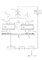
図5は、上記実施形態の流体濃度測定装置10の電気的構成の一例を纏めて示すブロック線図である。図1〜4に示した装置では、発光素子ドライバーにより駆動された発光素子25から発光された光は、2本の光ファイバー26,27を介して互いに同じ光強度で伝達され、樹脂チューブTBの、発光部22に近い側のチューブ壁と、その樹脂チューブTBの内部を流れる血液BTと、発光部から遠い側(反対側)すなわち受光部24に近い側のチューブ壁とを透過し、互いに異なる固定距離L,lの光路を経て、ラインセンサ35の複数の受光素子35aによって受光される。ラインセンサ35は、例えば128個の受光素子35aを8μmピッチで有し、それらの受光素子35aは、あらかじめ受光強度が互いに等しくなるよう調整されて、受光した光の強度に応じたレベルの電気信号を出力し、CCD(電荷結合素子)は、それらの電気信号を経時的に並べてアナログ信号として出力する。
FIG. 5 is a block diagram collectively showing an example of the electrical configuration of the fluid
この例では、発光素子ドライバーが発光素子25を発光させ、ラインセンサドライバーが、ラインセンサ35から多数の発光素子35aの経時的に並んだアナログ信号を読み出してアナログデータとしてアナログ−デジタルコンバータ(A/D)に出力し、A/Dがそのアナログデータをデジタルデータに変換して流体濃度出力手段としての中央処理ユニット(CPU)に出力する。
In this example, the light emitting element driver causes the
CPUは、図示しないメモリにあらかじめ記憶したプログラムに基づき、A/Dの出力するデジタルデータからラインセンサ35の多数の受光素子35aのうち二箇所の発光供給箇所Sからの光と光軸が一致する二つの受光素子35aを含む所定の位置の複数の受光素子35aが各々受光した光の強度を求め、例えば、それら受光した光の強度と、光供給箇所Sから受光箇所Rまでの光路の長さL,lとから、ランベルト−ベールの法則に基づき、光路長さが異なる二種類の条件で濃度測定値を求める。なお、ランベルト−ベールの法則に基づく具体的な計算方法については、本願出願人が先に出願したPCT/JP2013/54664号国際出願(WO2014/050162号国際公開パンフレット)やPCT/JP2013/61486号国際出願(WO2014/170985号国際公開パンフレット)に詳細に記載されている。
Based on a program stored in advance in a memory (not shown), the CPU matches the optical axis with the light from the two light emission supply points S among the many
次いで、この発明の流体濃度測定装置の他の実施形態について図6〜8に基づき説明する。この実施形態の流体濃度測定装置50は、発光部および受光部からなる測定部を2組備える点で先の実施形態の流体濃度測定装置10とは異なる。
Next, another embodiment of the fluid concentration measuring apparatus according to the present invention will be described with reference to FIGS. The fluid
図6および図7に示すように、この流体濃度測定装置50は、装置50の主要部を収容する筐体52と、該筐体52にヒンジ54を介して開閉自在に連結された蓋体56と、ヒンジ54の反対側に設けられ、筐体52に対する蓋体56の閉塞姿勢を保持するフックの如き緊締具58を備える。
As shown in FIGS. 6 and 7, the fluid
筐体52は、互いに対向する前壁52aおよび後壁52bと、互いに対向配置され前壁52aおよび後壁52b間をつなぐ右側壁52cおよび左側壁52dと、これら壁52a〜52dの上端をつなぐ上壁52eとを有する。
The
筐体52の上壁52eには、光透過性でかつ変形可能な管路としての樹脂製チューブ(樹脂チューブ)が装着される上向きに開口する2つの溝60A,60Bが前後方向に互いに離間して形成されており、これらの溝60A,60Bは筐体52の左右側壁52c,52d間に直線状に延びる。各溝60A,60Bの幅は長手方向の両端部において小さく、両端部間の中間部において僅かに拡大されている。両端部における溝幅は、溝60A,60Bに装着される樹脂チューブの外径と同じか若しくはそれよりも僅かに大であることが好ましい。
On the
図8(a)に示すように、流体濃度測定装置50は、2つの発光部62A,62Bおよび2つの受光部64A,64Bを備えており、溝60A,60Bの幅方向で向かい合わせに配置された発光部62Aと受光部64Aおよび発光部62Bと受光部64Bがそれぞれ対をなす。なお、発光部62A,62Bおよび受光部64A,64Bの構成は、先の実施形態の装置における発光部22および受光部24と同じであり、詳細な説明は省略するとともに付随する発光素子や光ファイバー等の図示も省略している。
As shown in FIG. 8A, the fluid
発光部62A,62Bおよび受光部64A,64Bの保持構造について説明すると、流体濃度測定装置50は発光部62A,62Bを保持する、それぞれ作動部材としての2つの揺動部材68A,68Bを備えている。各揺動部材68A,68Bは、前後方向に沿う縦断面(図8(a))でみて2つの脚部68Aa,68Ab,68Ba,68Bbがその基端部において一体につながる略I字形をなし、その連結部近傍において、軸部70A,70Bを介して樹脂チューブTBの延在方向に沿う軸線周りに揺動可能に筐体52に支持されている。軸部70A,70Bよりも下方に延びる一方の脚部68Aa,68Baの末端部には後述のコイルスプリングを受ける凹部72A,72Bがその底面を後方に向けるように形成されている。軸部70A,70Bよりも上に延びる他方の脚部68Ab,68Bb上部には発光部62A,62Bの図示しない2本の光ファイバーの末端部が挿通され支持されている。この上側の脚部68Ab,68Bb上部の、各光ファイバーの末端に設けられたボールレンズ74A,74Bを露出させる壁部は溝60A,60Bの側壁部の一部を構成することとなる。上側の脚部68Ab,68Bbの下部(下面)には、先の実施形態で説明したものと同様の光ファイバー固定板75A,75Bおよび発光素子保持板76A,76Bが取り付けられ、これらの光ファイバー固定板75A,75Bおよび発光素子保持板76A,76Bは揺動部材68A,68Bと一緒に揺動する。
The holding structure of the
他方、受光部64A,64Bにおけるラインセンサ78A,78Bは断面略コ字状のセンサ保持部材79A,79B内に保持されている。センサ保持部材79A,79Bの垂壁は溝60A,60Bの側壁部の一部を構成する。これらの垂壁には樹脂チューブTB内を透過してきた光をラインセンサ78A,78Bに向けて通過させる図示しない2つの通路(貫通孔)が形成され、各通路の始端にはボールレンズ80A,80Bが固定されている。
On the other hand, the
揺動部材68A,68Bは、溝60A,60Bとヒンジ54との間で筐体52の上壁52eに昇降可能に保持されかつ頭部が筐体52の上壁52eから突出して蓋体56によって押下される押下部材82と、押下部材82の降下動作を水平動作に変換するとともに該水平動作を2つの揺動部材68A,68Bに同時に伝達する伝達部材84とによって揺動される。
The swinging
伝達部材84は、図7(b)に示すように板状に形成され、図7(a)に示すようにその側部において筐体52の下部に、コロ85aおよび長孔85bからなるガイド85を介して前後方向に移動可能に支持されている。伝達部材84には各揺動部材68A,68Bの下側の脚部68Aa,68Baに対応した窓孔84a,84bが形成され、該脚部68Aa,68Baの凹部72A,72Bと窓孔84a,84bとの間には弾性部材としてのコイルスプリング86A,86Bが介装されている。また伝達部材84は、図8(a)に示すように後端に押下部材82の下部に設けられたローラ82aに当接するとともに押下部材82の降下動作を水平動作に変換するカム面84c(傾斜面)を有する。これにより、押下部材82が押し下げられると、カム面84cを介して伝達部材84は前方(図8(a)において左方向)に移動し、伝達部材84は2つのコイルスプリング86A,86Bを同時に圧縮し、圧縮された各コイルスプリング86A,86Bは揺動部材68A,68Bを軸部70A,70Bを中心に図8(a)において時計回りに揺動させる。
The
揺動部材68A,68Bの揺動角は、センサ保持部材79A,79Bと揺動部材68A,68Bとの間にそれぞれ設けられたストッパ部材88A,88Bによって規制される。ストッパ部材88A,88Bは、溝60A,60B内における揺動部材68A,68Bとセンサ保持部材79A,79Bとの間の距離、ひいては光供給箇所Sと受光箇所Rとの距離を一定に保持するとともに、光供給箇所Sと受光箇所Rとが整列(光軸が一致)した状態で揺動部材68A,68Bを位置決めする機能を有する。
The swing angles of the
また、この実施形態の流体濃度測定装置50では、伝達部材84の前端と筐体52下部との間に、伝達部材84を後方に付勢する別のコイルスプリング90が設けられている。蓋体56が開放された状態では当該コイルスプリング90が伝達部材84を後方に移動させ、伝達部材84の上記窓孔84a,84bの前縁部が揺動部材68A,68Bの下側の脚部68Aa,68Baを後方に押圧して軸部70A,70Bを中心に図8(a)において反時計回りに揺動させる。このコイルスプリング90は、溝60A,60B内において揺動部材68A,68Bとセンサ保持部材79A,79Bとが離間する方向に揺動部材68A,68Bを間接的に付勢して、溝60A,60B内に樹脂チューブTBの着脱のための十分な空間を形成する付勢部材として機能する。
Further, in the fluid
かかる構成例の流体濃度測定装置50にあっては、図8(a)に示すように、蓋体56が開放された状態では、揺動部材68A,68Bを溝60A,60B内の光供給箇所S(この例では発光部62A,62Bのボールレンズ74A,74B)と受光箇所R(この例では受光部64A,64Bのボールレンズ80A,80B)とを離間させる方向に揺動させることで、樹脂チューブTBを溝60A,60B内に容易に挿入することができる。特に、溝60A,60B内の光供給箇所Sと受光箇所Rとが離間する方向に伝達部材84を介して揺動部材68A,68Bを付勢するコイルスプリング90が設けられている場合には、蓋体56が開放されている状態では溝60A,60Bの狭窄部(光供給箇所Sと受光箇所Rとの間隙)が常時拡げられているため、溝60A,60Bへの樹脂チューブTBの着脱をより一層負荷なく行うことが可能となる。
In the fluid
そして、図8(b)に示すように筐体52の溝60A,60B内に樹脂チューブTBを装着し蓋体56を閉めると、蓋体56の閉動作に伴う押下部材82の押し下げに連動して伝達部材84がガイド85による案内下で前方に水平移動し、伝達部材84の窓孔84a,84b内に配置された2つのコイルスプリング86A,86Bが圧縮される。圧縮された2つのコイルスプリング86A,86Bは揺動部材68A,68Bを溝60A,60B内の光供給箇所Sと受光箇所Rとが接近する方向にそれぞれ揺動させ、各溝60A,60Bにおいて発光部62A,62Bの光供給箇所Sおよび受光部64A,64Bの受光箇所Rは共に樹脂チューブTBの表面に圧接される。このとき、揺動部材68A,68Bの揺動はストッパ部材88A,88Bによって規制され、樹脂チューブTBの表面上の光供給箇所Sと受光箇所Rとの間は常時一定間隔に保持される。
Then, as shown in FIG. 8B, when the resin tube TB is mounted in the
従って、この流体濃度測定装置50によれば、蓋体56が開放された状態では、測定時に狭窄部となる箇所の溝幅(光供給箇所Sと受光箇所Rとの間の間隙)を一時的に広げることができて樹脂チューブTBを無理なく溝60A,60B内に装着または溝60A,60Bから取り外すことができる。また、測定時には蓋体56の閉動作に連動して揺動部材68A,68Bが揺動し、発光部62A,62Bの光供給箇所Sと受光部64A,64Bの受光箇所Rとが接近するためこれらの光供給箇所Sおよび受光箇所Rを共に樹脂チューブTBに確実に圧接させることができるとともに、ストッパ部材88A,88Bによる揺動部材68A,68Bの揺動の規制により光供給箇所Rおよび受光箇所S間に常に一定の光路距離をもたらすことができ、かつ、従来のような樹脂チューブに生じる歪みや捩れを有効に防止して経時的に発生する管路の変形を効果的に阻止することができるため、正確な濃度測定が可能となる。さらに、この流体濃度測定装置50は2つの測定部を有するので、例えば血液透析療法における血液透析前後の血液の濃度測定が一台の流体濃度測定装置により可能となる。
Therefore, according to the fluid
さらに、この実施形態の流体濃度測定装置50では、押下部材82はヒンジ54と後方の溝60Aとの間でヒンジ54に近接して設けられているため、押下部材82を作用点とする大きなモーメントアームを確保することができるため、より小さい力で蓋体56による押下部材82の押し下げ、ひいては揺動部材68A,68Bの揺動を行うことができる。同様に、伝達部材84からの押圧力を軸部70A,70Bから離れた、揺動部材68A,68Bの脚部68Aa,68Ba末端部(凹部72A,72B)で受けるようにしているため、支点である軸部70A,70Bと力点であるコイルスプリング86A,86Bによる押圧箇所との間に大きなモーメントアームを確保することができ、より一層小さな力で蓋体56による押下部材82の押し下げ、ひいては揺動部材68A,68Bの揺動を行うことができる。
Further, in the fluid
以上、図示例に基づき説明したが、この発明は上述の例に限定されるものでなく特許請求の範囲の記載範囲内で適宜変更し得るものである。例えば上述した実施形態の装置10,50では、揺動部材38,68A,68Bは発光部22,62A,62Bを保持して発光部22,62A,62Bを受光部24,64A,64Bに対して近接離間させる例を示したが、これに代えて揺動部材38,68A,68Bは受光部24,64A,64Bを保持し受光部24,64A,64Bを発光部22,62A,62Bに対して近接離間させてもよい。あるいは、各溝20,60A,60B内で揺動部材を互いに対向するよう2つ設け、一方の揺動部材に発光部22,62A,62Bを保持させ、他方の揺動部材に受光部24,64A,64Bを保持させ、発光部22,62A,62Bおよび受光部24,64A,64Bを共に近接離間運動させるようにしてもよい。
As mentioned above, although demonstrated based on the example of illustration, this invention is not limited to the above-mentioned example, It can change suitably in the description range of a claim. For example, in the
また、上記実施形態の装置10,50では、弾性部材および付勢部材としてそれぞれコイルスプリング47,49,86A,86B,90を用いたが、これに限らず、板ばねやトーションばね等の他の形式のばね、あるいはゴムを用いてもよい。
In the
さらに、上記実施形態の装置10,50では、作動部材として溝20,60A,60Bの延在方向に沿う軸線周りに揺動自在な揺動部材38,68A,68Bを備えるものであったが、これに限らず、作動部材として押下部材46,82の下降移動を伝達して発光部22および受光部24間を近接、離間させるカム機構あるいはリンク機構を用いてもよい。
Furthermore, in the
さらに、上記実施形態の装置10,50では、各溝20,60A,60B内に光供給箇所Sを2つ設けたが、光供給箇所Sは少なくとも1つあればよい。あるいは3箇所以上の光供給箇所Sで光を供給し、その光をラインセンサ35,78A,78Bで受光して光の強度を求め、その光の強度から流体濃度をより高精度に求めるようにしてもよい。さらに、光供給箇所Sへの光供給手段も図示例に限らず、各光供給箇所Sに発光素子を直接それぞれ配置してもよい。
Furthermore, in the
さらに、上記実施形態の装置10,50では、受光のために多数の受光素子を有するラインセンサ35,78A,78Bを用いると説明したが、これに限らず各受光位置に単一の受光素子を配置したものであってもよい。また、ラインセンサは複数本並列にして管路の延在方向に配置し、あるいは少なくとも管路の延在方向に整列する多数の画素を有する2次元光センサで代用してもよく、このようにすれば、管路の周方向あるいは接線方向の光軸のずれにも対応することができる。
Furthermore, in the
さらに、上記実施形態の装置では、液体としての血液の濃度を測定することができるが、他の液体の濃度測定に用いることもでき、その場合には光源から供給する光として、その液体による吸収率が高い波長の光を選択するのが好ましい。 Furthermore, in the apparatus of the above embodiment, the concentration of blood as a liquid can be measured, but it can also be used for measuring the concentration of other liquids. In this case, the light supplied from the light source is absorbed by the liquid. It is preferable to select light of a wavelength with a high rate.
そして、上記実施形態の装置では、CPUが、受光素子が出力する光の強度に基づき演算処理を行って血液濃度を求め、それを出力しているが、これに代えて、ラインセンサの所定範囲の受光素子が出力する光の強度の複数種類の分布パターンあるいはその所定範囲の分布パターンで囲まれる領域の面積を、あらかじめ取得してメモリ等に記憶してある複数種類の流体濃度のそれぞれについての分布パターンの形状あるいは面積と比較し、一致しない場合はデータ間を補完することで、流体濃度を求めるようにしてもよく、このようにすれば、多数の受光素子が受光した光の強度から短時間で容易に流体の濃度を求めて出力することができる。 In the apparatus of the above embodiment, the CPU performs a calculation process based on the intensity of the light output from the light receiving element to obtain the blood concentration and outputs it, but instead, a predetermined range of the line sensor is output. For each of the multiple types of fluid concentrations obtained in advance and stored in the memory or the like, the areas of the regions surrounded by the multiple types of distribution patterns of the light intensity output from the light receiving element or the distribution pattern of the predetermined range are stored. In comparison with the shape or area of the distribution pattern, if they do not match, the data concentration may be complemented to obtain the fluid concentration. In this way, the light intensity received by the many light receiving elements is reduced. The concentration of the fluid can be easily obtained and output in time.
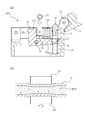
上述した蓋体の開閉と連動した、発光部および受光部の、樹脂チューブへの圧接およびその解放は流体濃度測定装置に限らず、変形可能な管路としての樹脂チューブ内を流れる液体中の気泡(マイクロバブルを含む。)を検出する装置にも用いることができる。図9は、この発明に従う一実施形態の気泡検出装置を示し、(a)は縦断面図、(b)はこの気泡検出装置の発信部と受信部との間に樹脂チューブを挟み込んで気泡の検出を行う様子を模式的に示した横断面図である。なお、図1〜4で示した実施形態の流体濃度測定装置における要素と同様の要素には同一の符号を付けて詳細な説明は省略する。 The pressure contact and release of the light emitting part and the light receiving part to the resin tube in conjunction with the opening and closing of the lid described above are not limited to the fluid concentration measuring device, but bubbles in the liquid flowing in the resin tube as a deformable conduit It can also be used for a device that detects (including microbubbles). 9A and 9B show a bubble detection device according to an embodiment of the present invention, in which FIG. 9A is a longitudinal sectional view, and FIG. 9B is a view of the bubble formed by sandwiching a resin tube between the transmission portion and the reception portion of the bubble detection device. It is the cross-sectional view which showed typically a mode that detection was performed. In addition, the same code | symbol is attached | subjected to the element similar to the element in the fluid concentration measuring apparatus of embodiment shown in FIGS. 1-4, and detailed description is abbreviate | omitted.
この気泡検出装置100は、図1〜4で示した流体濃度測定装置10における発光部22に代えて、樹脂チューブTBの表面に対して超音波を発信する発信部102を備えるとともに、受光部24に代えて、樹脂チューブTBを透過した超音波を受信する受信部104を備える。発信部102は作動部材としての揺動部材38に保持されている。かかる構成の装置100の溝20に樹脂チューブTBを装着し、蓋体16を閉めると蓋体16によって押下部材46が押し下げられ、弾性部材としてのコイルスプリング47を介して揺動部材38が揺動し、発信部102と受信部104との間に樹脂チューブTBが所定の押圧下で挟持される。これにより、発信部102から発信された超音波を確実に樹脂チューブTBに伝達させかつ樹脂チューブTBおよびその内部の流体を透過した超音波を受信部104で確実に受信することができる。樹脂チューブTBおよびその内部の流体を透過した超音波は受信部104が受信し、図示しない演算部、例えばCPUが超音波の受信強度に基づき、および/または、超音波の発信から受信までに要した時間に基づき樹脂チューブTB内の気泡の有無を検出する。
The
なお、この発明の気泡検出装置にあっては、図5〜8で示した流体濃度測定装置と同様、溝および揺動部材を2組備え、押下部材の押し下げに連動して2つの揺動部材を同時に揺動させる伝達部材を備えていてもよい。この場合、伝達部材を付勢して、発信部と受信部とが互いに離間する方向に揺動部材を揺動させる付勢部材を備えてもよい。 In the bubble detection device of the present invention, as with the fluid concentration measurement device shown in FIGS. 5 to 8, two sets of grooves and swinging members are provided, and two swinging members are interlocked with the depression of the pressing member. It is also possible to provide a transmission member that swings simultaneously. In this case, a biasing member that biases the transmission member and swings the swinging member in a direction in which the transmitting unit and the receiving unit are separated from each other may be provided.
かくしてこの発明の流体濃度測定装置によれば、装置への管路の着脱が容易であり、かつ、発光部および受光部を管路に対して確実に密着させて正確な濃度測定を行うことが可能である。またこの発明の気泡検出装置によれば、装置への管路の着脱が容易であり、かつ、超音波の発信部および受信部を管路に対して確実に密着させて正確な気泡検出を行うことが可能である。 Thus, according to the fluid concentration measuring device of the present invention, it is easy to attach and detach the conduit to the device, and it is possible to accurately measure the concentration by securely bringing the light emitting portion and the light receiving portion into close contact with the conduit. Is possible. Further, according to the bubble detection device of the present invention, it is easy to attach and detach the pipeline to the device, and accurate bubble detection is performed by reliably bringing the ultrasonic wave transmitting and receiving portions into close contact with the pipeline. It is possible.
10,50 流体濃度測定装置
12,52 筐体
14,54 ヒンジ
16,56 蓋体
18,58 緊締具
20,60A,60B 溝
22,62A,62B 発光部
24,64A,64B 受光部
25 発光素子
26,27 光ファイバー
29,30,74A,74B ボールレンズ,光供給箇所
31,75A,75B 光ファイバー固定板
32,76A,76B 発光素子保持板
35,78A,78B ラインセンサ
36,37,80A,80B ボールレンズ,受光箇所
38,68A,68B 揺動部材(作動部材)
39,70A,70B 軸部
44,79A,79B センサ保持部材
46,82 押下部材
47,86A,86B コイルスプリング(弾性部材)
48,88A,88B ストッパ部材
49,90 コイルスプリング(付勢部材)
84 伝達部材
84c カム面
85 ガイド
100 気泡検出装置
102 発信部
104 受信部
DESCRIPTION OF
39, 70A,
48, 88A,
84
Claims (5)
前記管路が装着される上向きに開口する溝が形成された筐体と、
前記溝の一方の側面側に配置され、前記管路の表面上に光を供給する発光部と、
前記溝の他方の側面側に前記発光部に対向配置され、前記管路を透過した光を受光する受光部と、
ヒンジを介して前記筐体に開閉可能に連結され、閉姿勢にて前記溝の上部開口を閉止する蓋体と、
前記筐体に昇降可能に保持され、前記蓋体の閉動作に伴い該蓋体によって押し下げられる押下部材と、
前記発光部または前記受光部を保持するとともに前記押下部材の押し下げに連動して作動することで対向する前記発光部と前記受光部とを互いに接近させる作動部材と、
前記作動部材の作動を規制して前記発光部および前記受光部間を所定間隔に保持するストッパ部材と、を備えることを特徴とする流体濃度測定装置。 A fluid concentration measuring device for measuring the concentration of a fluid flowing in a light transmissive and deformable pipe,
A housing formed with an upwardly opening groove to which the conduit is mounted;
A light-emitting unit disposed on one side of the groove and supplying light onto the surface of the conduit;
A light receiving portion that is disposed opposite to the light emitting portion on the other side surface side of the groove and receives light transmitted through the conduit;
A lid that is openably and closably connected to the housing via a hinge, and closes the upper opening of the groove in a closed position;
A pressing member that is held by the casing so as to be movable up and down, and is pushed down by the lid in accordance with a closing operation of the lid;
An operation member that holds the light emitting unit or the light receiving unit and moves the light emitting unit and the light receiving unit facing each other by operating in conjunction with the pressing of the pressing member;
A fluid concentration measuring device comprising: a stopper member that regulates the operation of the operating member and holds the light emitting unit and the light receiving unit at a predetermined interval.
前記押下部材の押し下げに連動して2つの作動部材を同時に作動させる伝達部材を備える、請求項1に記載の流体濃度測定装置。 Two sets of the groove and the actuating member;
The fluid concentration measuring apparatus according to claim 1, further comprising a transmission member that simultaneously operates two operating members in conjunction with the pressing of the pressing member.
前記管路が装着される上向きに開口する溝が形成された筐体と、
前記溝の一方の側面側に配置され、前記管路の表面上に超音波を発信する発信部と、
前記溝の他方の側面側に前記発信部に対向配置され、前記管路を透過した超音波を受信する受信部と、
ヒンジを介して前記筐体に開閉可能に連結され、閉姿勢にて前記溝の上部開口を閉止する蓋体と、
前記筐体に昇降可能に保持され、前記蓋体の閉動作に伴い該蓋体によって押し下げられる押下部材と、
前記発信部または前記受信部を保持するとともに前記押下部材の押し下げに連動して作動することで対向する前記発信部と前記受信部とを互いに接近させる作動部材と、
前記作動部材の作動を規制して前記発信部および前記受信部間を所定間隔に保持するストッパ部材と、を備えることを特徴とする気泡検出装置。
A bubble detection device for detecting the presence or absence of bubbles in a fluid flowing in a deformable pipe,
A housing formed with an upwardly opening groove to which the conduit is mounted;
A transmitter that is disposed on one side of the groove and transmits ultrasonic waves on the surface of the pipe;
A receiving unit that is disposed opposite to the transmitting unit on the other side surface of the groove and receives the ultrasonic wave transmitted through the conduit;
A lid that is openably and closably connected to the housing via a hinge and closes the upper opening of the groove in a closed position;
A pressing member that is held in the casing so as to be movable up and down, and is pushed down by the lid in accordance with the closing operation of the lid;
An operating member that holds the transmitting unit or the receiving unit and moves the opposing transmitting unit and the receiving unit closer to each other by operating in conjunction with the pressing of the pressing member;
A bubble detection device comprising: a stopper member that regulates the operation of the operation member and holds the transmission unit and the reception unit at a predetermined interval.
Priority Applications (1)
| Application Number | Priority Date | Filing Date | Title |
|---|---|---|---|
| JP2015242319A JP6620002B2 (en) | 2015-12-11 | 2015-12-11 | Fluid concentration measuring device and bubble detecting device |
Applications Claiming Priority (1)
| Application Number | Priority Date | Filing Date | Title |
|---|---|---|---|
| JP2015242319A JP6620002B2 (en) | 2015-12-11 | 2015-12-11 | Fluid concentration measuring device and bubble detecting device |
Publications (2)
| Publication Number | Publication Date |
|---|---|
| JP2017106865A JP2017106865A (en) | 2017-06-15 |
| JP6620002B2 true JP6620002B2 (en) | 2019-12-11 |
Family
ID=59059496
Family Applications (1)
| Application Number | Title | Priority Date | Filing Date |
|---|---|---|---|
| JP2015242319A Active JP6620002B2 (en) | 2015-12-11 | 2015-12-11 | Fluid concentration measuring device and bubble detecting device |
Country Status (1)
| Country | Link |
|---|---|
| JP (1) | JP6620002B2 (en) |
Families Citing this family (4)
| Publication number | Priority date | Publication date | Assignee | Title |
|---|---|---|---|---|
| CN109085236B (en) * | 2018-08-23 | 2021-01-22 | 株洲时代新材料科技股份有限公司 | Method for detecting the content of air bubbles in the process of defoaming of resin and curing agent by ultrasonic |
| CN113702337A (en) * | 2020-05-20 | 2021-11-26 | 桂林云璟科技有限公司 | Liquid detection device |
| JP7549203B2 (en) * | 2020-10-22 | 2024-09-11 | 澁谷工業株式会社 | Air Bubble Detector |
| KR20250092310A (en) * | 2023-12-14 | 2025-06-24 | 주식회사 메디포스 | Infusion tube state determination device and method |
Family Cites Families (7)
| Publication number | Priority date | Publication date | Assignee | Title |
|---|---|---|---|---|
| JPS6173439U (en) * | 1984-10-22 | 1986-05-19 | ||
| US5192510A (en) * | 1991-01-30 | 1993-03-09 | E. I. Du Pont De Nemours And Company | Apparatus for performing fluorescent assays which separates bulk and evanescent fluorescence |
| JP3447957B2 (en) * | 1998-06-02 | 2003-09-16 | 株式会社ジェイ・エム・エス | Bubble detector |
| JP2003065952A (en) * | 2001-08-24 | 2003-03-05 | Kosu:Kk | Dissolved-ozone concentration meter |
| JP2005127802A (en) * | 2003-10-22 | 2005-05-19 | Arkray Inc | Analyzer |
| JP4389576B2 (en) * | 2003-12-17 | 2009-12-24 | コニカミノルタセンシング株式会社 | Analysis equipment |
| EP2988113B1 (en) * | 2013-04-18 | 2024-09-18 | Nipro Corporation | Fluid concentration measuring device |
-
2015
- 2015-12-11 JP JP2015242319A patent/JP6620002B2/en active Active
Also Published As
| Publication number | Publication date |
|---|---|
| JP2017106865A (en) | 2017-06-15 |
Similar Documents
| Publication | Publication Date | Title |
|---|---|---|
| JP6620002B2 (en) | Fluid concentration measuring device and bubble detecting device | |
| CN105229448B (en) | Fluid concentrations determine device | |
| CN101551281B (en) | Fluorescence temperature sensor | |
| ATE451606T1 (en) | SENSOR WITH POLYMER COMPONENTS | |
| WO2008107842A3 (en) | Medical apparatus with a sensor for detecting a force | |
| WO2008043915A3 (en) | Device for conveying a substance provided with an optical leak detector | |
| KR101712031B1 (en) | Biosensor optical system for performing noninvasive glucose monitoring | |
| JP2012510053A (en) | Flow cell optical detection system | |
| WO2006079043A3 (en) | Pulse oximetry grip sensor and method of making same | |
| EP3198268A1 (en) | An improved apparatus for measuring hexavalent chromium in water | |
| CN107533004B (en) | Transmitted Light Intensity Measurement Unit | |
| US20150346092A1 (en) | Apparatus and method for measuring properties of fluids | |
| KR20140121768A (en) | Analyzing device | |
| KR20210029136A (en) | Temperature measurement sensor, temperature measurement system, and temperature measurement method | |
| CN102853879A (en) | liquid sensor | |
| CN110199189A (en) | Optical flow cell | |
| PL1705473T3 (en) | Measuring device for measuring the refraction properties of optical lenses | |
| CN210604381U (en) | Bacteria turbidimeter | |
| TW200734708A (en) | Connector for two-way optical communications | |
| JP4087291B2 (en) | Tube liquid sensor | |
| KR20130106688A (en) | Apparatus and system for detecting fluorescence | |
| CN212674894U (en) | Water quality detection device | |
| WO2017208661A1 (en) | Liquid sensor and tube holding member of liquid sensor | |
| ATE427534T1 (en) | OPTOELECTRONIC DEVICE | |
| TW202346836A (en) | Fluid concentration measuring device |
Legal Events
| Date | Code | Title | Description |
|---|---|---|---|
| A621 | Written request for application examination |
Free format text: JAPANESE INTERMEDIATE CODE: A621 Effective date: 20181204 |
|
| TRDD | Decision of grant or rejection written | ||
| A977 | Report on retrieval |
Free format text: JAPANESE INTERMEDIATE CODE: A971007 Effective date: 20191016 |
|
| A01 | Written decision to grant a patent or to grant a registration (utility model) |
Free format text: JAPANESE INTERMEDIATE CODE: A01 Effective date: 20191030 |
|
| A61 | First payment of annual fees (during grant procedure) |
Free format text: JAPANESE INTERMEDIATE CODE: A61 Effective date: 20191118 |
|
| R150 | Certificate of patent or registration of utility model |
Ref document number: 6620002 Country of ref document: JP Free format text: JAPANESE INTERMEDIATE CODE: R150 |
|
| R250 | Receipt of annual fees |
Free format text: JAPANESE INTERMEDIATE CODE: R250 |
|
| R250 | Receipt of annual fees |
Free format text: JAPANESE INTERMEDIATE CODE: R250 |
|
| R250 | Receipt of annual fees |
Free format text: JAPANESE INTERMEDIATE CODE: R250 |
|
| R250 | Receipt of annual fees |
Free format text: JAPANESE INTERMEDIATE CODE: R250 |